EP0803842A2 - Binärbilderzeugungsgerät - Google Patents
Binärbilderzeugungsgerät Download PDFInfo
- Publication number
- EP0803842A2 EP0803842A2 EP97103555A EP97103555A EP0803842A2 EP 0803842 A2 EP0803842 A2 EP 0803842A2 EP 97103555 A EP97103555 A EP 97103555A EP 97103555 A EP97103555 A EP 97103555A EP 0803842 A2 EP0803842 A2 EP 0803842A2
- Authority
- EP
- European Patent Office
- Prior art keywords
- image
- sample
- shade
- shading
- point
- Prior art date
- Legal status (The legal status is an assumption and is not a legal conclusion. Google has not performed a legal analysis and makes no representation as to the accuracy of the status listed.)
- Granted
Links
Images


Classifications
-
- G—PHYSICS
- G06—COMPUTING OR CALCULATING; COUNTING
- G06T—IMAGE DATA PROCESSING OR GENERATION, IN GENERAL
- G06T5/00—Image enhancement or restoration
- G06T5/90—Dynamic range modification of images or parts thereof
- G06T5/94—Dynamic range modification of images or parts thereof based on local image properties, e.g. for local contrast enhancement
-
- G—PHYSICS
- G06—COMPUTING OR CALCULATING; COUNTING
- G06T—IMAGE DATA PROCESSING OR GENERATION, IN GENERAL
- G06T5/00—Image enhancement or restoration
- G06T5/40—Image enhancement or restoration using histogram techniques
-
- G—PHYSICS
- G06—COMPUTING OR CALCULATING; COUNTING
- G06V—IMAGE OR VIDEO RECOGNITION OR UNDERSTANDING
- G06V30/00—Character recognition; Recognising digital ink; Document-oriented image-based pattern recognition
- G06V30/10—Character recognition
- G06V30/16—Image preprocessing
- G06V30/162—Quantising the image signal
-
- G—PHYSICS
- G06—COMPUTING OR CALCULATING; COUNTING
- G06V—IMAGE OR VIDEO RECOGNITION OR UNDERSTANDING
- G06V30/00—Character recognition; Recognising digital ink; Document-oriented image-based pattern recognition
- G06V30/10—Character recognition
Definitions
- the present invention relates to a binary image forming device which is capable of extracting objects such as characters and lines with no influence of shading by previously removing shade (partial darkness) from a shade-containing image.
- a conventional representative method of forming a binary image is such that it prepares first an optical density histogram indicating a correlation between density values and the number of their occurrences (frequency values), calculates a binalizing threshold by a method such as discriminant analysis and quantizes an image into a set of binary coded signals according to the threshold value. Since this method binalizes all pixels within an image according to the same threshold, it is effective for binalizing an image whose background has an even optical density but can not obtain a suitable threshold for binarizing an image having an uneven background density caused by shading or like partial darkness.
- an object of the present invention to provide a binary image forming device which is capable of generating a desirable binary image by eliminating the effect of shading from an input image by calculating a background density, determining shading of the image and then extracting objects (characters and lines) only and entirely, i.e., without erasing any object even if the objects are shaded or vaguely contoured objects and coexists with distinctly contoured objects in the image.
- the binary image forming device can not assure that all reference blocks for all sample points contain their background areas.
- Fig. 1 is a block diagram showing a construction of a binary image forming device which is a first embodiment of the present invention.
- Fig. 2 is a flow chart for explaining operations of the first embodiment of the present invention.
- Fig. 3 is a view for explaining how to set a sample point and a reference block in the first embodiment of the present invention.
- Fig. 4 shows a locational relation between a pixel (X) and neighboring sample points (A, B, C, D) when calculating for interpolation of shades at other points other than the sample points in the first embodiment of the present invention.
- Fig. 5A to Fig. 5E are views for explaining an example of application of the present invention to processing an image of an automobile's license plate.
- Fig. 6 is a block diagram showing a construction of a binary image forming device which is the second embodiment of the present invention.
- Fig. 7 is a flow chart for explaining operations of the second embodiment of the present invention.
- Fig. 8 shows an example of reference blocks set by one for each sample point in second and third embodiments of the present invention.
- Fig. 9 is a block diagram showing a construction of a binary imageforming device which is the third embodiment of the present invention.
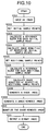
- Fig. 10 is a flow chart for explaining operations of the third embodiment of the present invention.
- Fig. 11 shows initial sample points and additional sample points in the third embodiment of the present invention.
- Fig. 1 is a block diagram of a binary image forming device which is the first embodiment of the present invention.
- the binary image forming device which comprises an image input portion 101 (e.g., a charge-coupled camera) for inputting an image to be converted into a binary image, a sample point setting portion 102 for setting sample points 30 one for a specified number of pixels composing the input image; a sample-point shade calculating portion 103 for setting a reference block of specifided size for each sample point located at a center thereof and determining an optical density of shading at each sample point from a density distribution of pixels in each reference block; a shade calculating portion 104 for generating a shading image by interpolating calculation of shade densities of the other pixels than the sample points on the basis of sample-point shading densities determined at respective sample points; a shade removing portion 105 for generating a shadeless image by removing the effect of shading according to the shade image generated by the shade calculating portion 104; a quantizing portion 106 for producing
- the device is supposed to work with an input image where an optical density of a background (i.e., all other portions than extractive objects) is larger (brighter) than an optical density of the objects to be extracted.
- a reverse case may be understood by reversing the density values of the object and the background.
- an image of a license plate for an automobile which is shown in Fig. 5A, will be quantized by the embodiment.
- An input image to be binarized is inputted through the image input portion 101 such as a charge-coupled camera (CCD) (Step S101). Characters in this input image contain shading as shown in Fig. 5A. A background in the input image includes all the other portions than extractive objects i.e., two Japanese characters accompanied figures 33, and figures 94-00.
- CCD charge-coupled camera
- the sample point setting portion 102 sets sample points 30 one for a certain number of pixels as shown in Fig. 3 (Step S102).
- a horizontal distance sx and a vertical distance sy between sample points are set to a possibly smallest value on the condition that a rectangle of sx by sy in size, which is extracted from any portion of the input image, must contain a background.
- sizes of extractive characters e.g., numbers on a license plate
- width of each character is preset to a value presumable from the whole frame size. If any extractive object can not correctly be defined in size, the sample point setting portion 102 requests a user to enter its size value through an interface therewith or it sets a value larger than a presumed size.
- the sample-point shade calculating portion 103 determines an optical shade density at each of sample point 30 set by the sample-point setting portion 102 (Step S103).
- a rectangle of sx by sy in size is set as a reference block 40 in such a way that a sample point 30 is located at a center of the rectangle.
- a reference block 40 for a sample point 30 existing at an edge portion of an image may have its part out of the image and, in this case, its part remaining within the image is considered to be effective.
- the sample-point shade calculating portion 103 performs following opera tions on each sample point 30:
- the mean optical density value t back obtained by step is taken as an optical density of shading at the sample point 30. This is based upon the fact that the optical density of background pixels is larger than that of any objective pixel within a limited area independent of whether shading exists or is absent thereat. As the rectangular reference block 40 always contains a background area, it enables effective determination of an optical density of the background at any sample point even if the later exists within an area of an objective character or a line figure.
- the shade calculating portion 104 determines the shade density of the other pixels except the sample point 30 by an interpolating method and generates a shade image (Step S104).
- Fig. 5B shows a shade image generated from an input image shown in Fig. 5A.
- a shade density of an optional pixel X except sample points is determined by linear interpolation from shade density values of sample points A, B, C and D, which are neighboring each other to surround the pixel X as shown in Fig. 4.
- a vector AX has the following relation with vectors AD and AB:
- AX ⁇ s * AD ⁇ + t * AB ⁇ (0 ⁇ s ⁇ 1, 0 ⁇ t ⁇ 1)
- I(A), I(B), I(C) and I(D) designate shade density values at sample points A, B, C and D respectively. This processing is carried out on all pixels except sample points to produce a shade image (Step S104).
- the shade removing portion 105 transforms the optical density of the input image according to the optical density of the shade image prepared by the shade calculating portion 104 and generates a shade-removed image (Step S105). Namely, the input image shown in Fig. 5A is relieved off the effect of the shade image of Fig. 5B to produce a shadeless image shown in Fig. 5C.
- Image data R (x, y) of the shadeless image is determined by the following expression, where I (x, y) is input image data and G(x, y) is shade image data.
- R(x,y) L ⁇ I (x, y) G (x, y)
- the Image data R(x, y) is obtained by conducting the above-mentioned calculation for each of pixels within the image. If G(x, y) accurately represents a shade of a background, optical densities I(x, y) of a background are converted all to L as shown in Expression (3). Consequently, a shadeless image with a background of an even optical density is produced as seen in Fig. 5C. L is a constant that must be set at an adequate value securing that R(x, y) may falls within a certain range of optical density levels (e.g., 0 - 255 for a 256-level gradation image).
- the quantizing portion 106 conducts binarizing processing on the shadeless image produced by the shade removing portion 105 by a simple method e.g., discriminant analysis (Step S106).
- a binary image shown in Fig. 5E is obtained from the shade-removed image of Fig. 5C.
- the obtained binary image is outputted by the image output portion 107 (Step S107).
- the image processing is completed at this step.
- the output image from the image output portion 107 may be displayed on a display or printed by a printer.
- Fig. 5A to Fig. 5E show an image of a license plate of an automobile, including an input image (Fig. 5A), a shade image (Fig. 5B) produced at Step S104, a shade-removed (shadeless) image (Fig. 5C) produced at Step S105 and a binary image (Fig. 5E) obtained by quantizing the shadeless image (Fig. 5C) by the discriminant analysis method.
- Fig. 6 is a block diagram of a binary image forming device which is the second embodiment of the present invention.
- the binary image forming device which comprises: an image input portion 201 (e.g., a charge-coupled camera) for inputting an image to be converted into a binary image; a sample point setting portion 202 for setting sample points 30 one for a certain number of pixels composing the input image; a reference block calculating portion 204 for setting a reference block 40 adaptable for calculating shading for each sample point; a sample-point shade calculating portion 203 for determining a shade density at each sample point from a density distribution of pixels in the reference block set by the reference block calculating portion 204; a shade calculating portion 205 for generating a shade image by interpolating calculation of shade densities of pixels except the sample points on the basis of sample-point shading densities determined at respective sample points; a shade removing portion 206 for generating a shadeless image by removing the effect of shading according to the shade image generated by the shade determining
- the device is supposed to work with an input image where an optical density of a background (i.e., all the other portions except extractive objects) is larger (brighter) than an optical density of the objects to be extracted.
- a reverse case may be understood by reversing the density values of the object and the background.
- An input image to be binarized is inputted through the image input portion 201 such as a charge-coupled camera (CCD) (Step S201).
- the sample point setting portion 202 sets sample point 30 at specified horizontal sx and vertical sy intervals (Step S202).
- the reference-block calculating portion 204 determines an edge image from the input image by using a Sobel filter and extracts edges (boundaries between extractive objects and a background) by binarization. Using the obtained binarized edge image, the portion 204 searches an edge being nearest from each sample point 30 and sets a possibly smallest rectangle including the sample point 30 at a center thereof and the found edge point, which is used as a reference block 40 for the sample point 30 (Step S203). Namely, since an image turns from a background to an object or from an object to a background at an edge point, the reference block obtained by the above-mentioned method always contains both a background area and an object area. In Fig.
- a left-hand reference block 40 is a horizontally and vertically prolonged rectangle since its sample point has a nearest edge point in a diagonal direction.
- a center reference block is a horizontally prolonged rectangle since its sample point finds an edge point in the horizontal direction.
- a right-hand reference block is vertically prolonged rectangle since its sample point has an edge point in the vertical direction.
- the sample-point shade calculating portion 203 determines an optical density of shading at each of sample points 30 according to the optical density distribution of input image pixels within each reference block, which was determined by the reference block calculating portion 204 (Step S204).
- the method of calculating the optical density of shading at a sample point 30 will not be further explained because it is the same as that described for the sample-point shade calculating portion 103 of the first embodiment, excepting the method of setting the reference blocks 40.
- the shade calculating portion 205 produces a shade image by determining optical densities of shading in the other areas except the sample point 30 by an interpolating method (Step S205), the shade removing portion 206 produces an shadeless image by eliminating the effect of the shading from the input image (Step S206), the quantizing portion 207 produces a binarized shadeless image (Step S207) and the image output portion 208 outputs the binary image (Step S208).
- Step S205 the shade calculating portion 205 produces a shade image by determining optical densities of shading in the other areas except the sample point 30 by an interpolating method
- the shade removing portion 206 produces an shadeless image by eliminating the effect of the shading from the input image (Step S206)
- the quantizing portion 207 produces a binarized shadeless image (Step S207)
- the image output portion 208 outputs the binary image (Step S208).
- the binary-quantizing device of the first embodiment can not always assure that every reference rectangle contains background areas.
- the binary image forming device of the second embodiment can always assure that each reference block 40 for each sample point 30 contains a background area and, therefore, it can produce a more accurate shade image and a more desirable binary image as compared with the first embodiment.
- This embodiment is inferior to the first embodiment in that it requires more time for calculation and an additional memory used for calculation of the binarized edge-image by the reference block calculating portion 204.
- the first embodiment is preferable to use on the condition that objects to be extracted in an input image have known sizes.
- Fig. 9 is a block diagram of a binary image forming device which is the third embodiment of the present invention.
- the binary image forming device which comprises: an image input portion 301 (e.g., a charge-coupled camera) for inputting an image to be converted into a binary image; an initial sample point setting portion 302 for setting initial sample points 30a one for a certain number of pixels composing the input image; an additional sample-point setting portion 303 for setting additional sample points 30b in accordance with shading of the input image, a reference block calculating portion 305 for setting reference blocks 40 adaptable for calculating shade at each of sample points 30a and 30b set by the initial sample-point setting portion 302 and the additional sample-point setting portion 303; a sample-point shade calculating portion 304 for determining an optical density of shading at each of the sample points set by the initial sample-point setting portion 302 and the additional sample-point setting portion 303 from a density distribution of pixels in each of the reference blocks set by the reference block calculating portion 305; a shade
- the device is supposed to work with an input image where an optical density of a background (i.e., all other portions except extractive objects) is larger (brighter) than an optical density of the objects to be extracted.
- a reverse case may be understood by reversing the density values of the object and the background.
- An input image to be binarized is inputted through the image input portion 301 such as a charge-coupled camera (CCD) (Step S301).
- the initial sample-point setting portion 302 sets initial sample points 30a at specified horizontal and vertical distances of sx and sy therebetween (Step S302).
- values of sx and sy are desirable to set in accordance with sizes of extractive objects in an input image. With an input image containing an object whose size can not accurately be defined, the parameters sx and sy may be set at values sufficiently larger than presumed values.
- the sample-point shade calculating portion 304 and the reference-block calculating portion 305 set reference blocks by one for each of the initial sample point 30a (Step S303) and determine an optical density value of shading for each initial sample point 30a by calculating optical densities of pixels within each reference block (Step S304).
- the processing operations of the sample-point shade calculating portion 304 and the reference-block calculating portion 305 are the same as those described for the sample-point shade calculating portion 203 and the reference-block calculating portion 204 of the second embodiment.
- the additional sample point setting portion 303 compares optical densities of shading at 4 neighbors of the initial sample points 30a, determines the number of additional sample points from differences of the shade densities between the initial sample points and sets the necessary number of additional sample points 30b (Step S305).
- 4 neighboring initial sample-points A, B, C and D are supposed to have optical densities I(A), I(B), I(C) and I(D) respectively. It is also assumed that a rectangle ABCD currently does not contains any other sample points than the above-denoted initial sample points.
- Dx INT(Max(
- Dy INT(Max(
- values Dx and Dy are determined and the rectangle ABCD is divided horizontally by Dx and vertically by Dy into Dx ⁇ Dy divisions (small rectangles). Additional sample points 30b are set one at each of vertices except vertices A, B, C and D.
- Max (x, y) represents a larger one of the values x and y
- INT(i) is an integer with a cut-off fraction
- BASE is a constant for controlling the number of sample points to be added.
- the above-mentioned operations are performed on every pairs of two neighbored points of 4 initial sample points for setting additional sample points.
- the sample-point shade calculating portion 304 and the reference block calculating portion 305 then set reference blocks for respective additional sample points 30b (Step S306), calculate a histogram of optical densities of pixels within each reference block and determine the optical density of shading at each additional sample point (Step S307).
- These processing steps are similar to the processing steps for determining shading at the initial sample points 30a, which in turn are similar to the processing steps described for the sample-point shade calculating portion 203 and the reference block calculating portion 204 of the second embodiment.
- the shade calculating portion 306 produces a shade image by interpolating calculation of optical densities of shading in areas except the sample points (Step S308)
- the shade removing portion 307 produces a shadeless image by removing the effect of shading from the input image (Step S309)
- the quantizing portion 308 produces a binary image by binarizing the shadeless image (Step S310)
- the image output portion 309 outputs the binary image (S311), by which the sequential operation of the device is completed.
- the binary image forming device can produce a shade image by adding any number of necessary sample points in accordance with shading condition of an input image and more accurately determine shading on the input image. Even in the case if sample points must be set at large intervals because objects to be extracted from an input image can not be measured, this embodiment can accurately determine a shade image by additionally setting necessary sample points, finally generating a more adequately binalized image.
- An binary image forming device mention in the first embodiment is designed to set sample points one for a certain number of pixels within an input image, set sample blocks of a specified size, each including one of the sample points at its center, determine optical density of shading at each sample point from a density distribution of pixels in the other areas except the sample points by calculating a distribution of pixels in the reference block, produce a shade image by calculating shading in the other areas except the sample points by interpolating method, produce a shadeless image by eliminating the shading effect from the input image by using the shade image and binalize the shadeless image.
- this device can produce a high-quality binary image from an input image containing self-shaded objects (e.g., characters and lines) or vaguely contoured and distinctly contoured objects by eliminating the shading effect without erasing self-shaded objects and by surely extracting vaguely contoured objects.
- self-shaded objects e.g., characters and lines
- vaguely contoured and distinctly contoured objects by eliminating the shading effect without erasing self-shaded objects and by surely extracting vaguely contoured objects.
- a binary image forming device mentioned in the second embodiment is further provided with a reference block calculating portion for setting reference blocks which are best suited in size and shape to respective sample points.
- the binary image forming device according to the first embodiment can not always assure that every reference rectangle contains background areas.
- the binary image forming device according to the second embodiment can always assure that each reference block for each sample point contains a background area and therefore, it can produce a more accurate shade image and a more desirable binary image.
- the binary image forming device mentioned in the third embodiment can produce a shade image by adding any number of necessary sample points in accordance with shading of an input image, which is measured at initial sample points, and more accurately determine shading on the input image than the devices mentioned in the first and second embodiment. Even in the case if sample points must be set at large intervals because objects to be extracted from an input image can not be measured in size, this embodiment can accurately calculate a shade image by additionally setting necessary sample points and finally generate a more desirable binary image.
Landscapes
- Engineering & Computer Science (AREA)
- Physics & Mathematics (AREA)
- General Physics & Mathematics (AREA)
- Theoretical Computer Science (AREA)
- Computer Vision & Pattern Recognition (AREA)
- Multimedia (AREA)
- Image Processing (AREA)
- Editing Of Facsimile Originals (AREA)
- Facsimile Image Signal Circuits (AREA)
- Character Input (AREA)
Applications Claiming Priority (3)
| Application Number | Priority Date | Filing Date | Title |
|---|---|---|---|
| JP06975796A JP3348167B2 (ja) | 1996-03-26 | 1996-03-26 | 画像2値化装置 |
| JP6975796 | 1996-03-26 | ||
| JP69757/96 | 1996-03-26 |
Publications (3)
| Publication Number | Publication Date |
|---|---|
| EP0803842A2 true EP0803842A2 (de) | 1997-10-29 |
| EP0803842A3 EP0803842A3 (de) | 1998-07-22 |
| EP0803842B1 EP0803842B1 (de) | 2002-09-04 |
Family
ID=13411997
Family Applications (1)
| Application Number | Title | Priority Date | Filing Date |
|---|---|---|---|
| EP97103555A Expired - Lifetime EP0803842B1 (de) | 1996-03-26 | 1997-03-04 | Vorrichtung zur Erzeugung eines Binärbildes |
Country Status (4)
| Country | Link |
|---|---|
| US (1) | US5912992A (de) |
| EP (1) | EP0803842B1 (de) |
| JP (1) | JP3348167B2 (de) |
| DE (1) | DE69715076T2 (de) |
Cited By (3)
| Publication number | Priority date | Publication date | Assignee | Title |
|---|---|---|---|---|
| WO2015105755A1 (en) * | 2014-01-08 | 2015-07-16 | Qualcomm Incorporated | Processing text images with shadows |
| EP3119074A1 (de) * | 2015-07-13 | 2017-01-18 | Canon Kabushiki Kaisha | Informationsverarbeitungsvorrichtung, informationsverarbeitungsverfahren und computerprogramm |
| US9888154B2 (en) | 2015-07-13 | 2018-02-06 | Canon Kabushiki Kaisha | Information processing apparatus, method for processing information, and computer program |
Families Citing this family (49)
| Publication number | Priority date | Publication date | Assignee | Title |
|---|---|---|---|---|
| JP3467725B2 (ja) | 1998-06-02 | 2003-11-17 | 富士通株式会社 | 画像の影除去方法、画像処理装置及び記録媒体 |
| US7016536B1 (en) * | 1999-11-24 | 2006-03-21 | Gtx Corporation | Method and apparatus for automatic cleaning and enhancing of scanned documents |
| SG103253A1 (en) | 2000-01-26 | 2004-04-29 | Kent Ridge Digital Labs | Method and apparatus for cancelling lighting variations in object recognition |
| US7324236B2 (en) * | 2000-02-01 | 2008-01-29 | Canon Kabushiki Kaisha | Discrepancy correction method and apparatus for correcting difference in levels of image signals obtained by an image sensor having a multiple output channels |
| JP2002109596A (ja) * | 2000-09-28 | 2002-04-12 | Nippon Conlux Co Ltd | 貨幣識別方法及び装置 |
| JP4377622B2 (ja) * | 2003-07-16 | 2009-12-02 | オリンパス株式会社 | シェーディング補正装置 |
| DE10356721B4 (de) * | 2003-12-02 | 2008-09-04 | Joachim Wischermann | Leuchtbild mit einem Tag- Nacht-Effekt |
| US7440633B2 (en) | 2003-12-19 | 2008-10-21 | Sharp Laboratories Of America, Inc. | Enhancing the quality of decoded quantized images |
| US7424166B2 (en) | 2003-12-24 | 2008-09-09 | Sharp Laboratories Of America, Inc. | Enhancing the quality of decoded quantized images |
| US7424168B2 (en) | 2003-12-24 | 2008-09-09 | Sharp Laboratories Of America, Inc. | Enhancing the quality of decoded quantized images |
| US7400779B2 (en) | 2004-01-08 | 2008-07-15 | Sharp Laboratories Of America, Inc. | Enhancing the quality of decoded quantized images |
| US8947465B2 (en) * | 2004-12-02 | 2015-02-03 | Sharp Laboratories Of America, Inc. | Methods and systems for display-mode-dependent brightness preservation |
| US7924261B2 (en) * | 2004-12-02 | 2011-04-12 | Sharp Laboratories Of America, Inc. | Methods and systems for determining a display light source adjustment |
| US8004511B2 (en) * | 2004-12-02 | 2011-08-23 | Sharp Laboratories Of America, Inc. | Systems and methods for distortion-related source light management |
| US8913089B2 (en) * | 2005-06-15 | 2014-12-16 | Sharp Laboratories Of America, Inc. | Methods and systems for enhancing display characteristics with frequency-specific gain |
| US7768496B2 (en) * | 2004-12-02 | 2010-08-03 | Sharp Laboratories Of America, Inc. | Methods and systems for image tonescale adjustment to compensate for a reduced source light power level |
| US7982707B2 (en) * | 2004-12-02 | 2011-07-19 | Sharp Laboratories Of America, Inc. | Methods and systems for generating and applying image tone scale adjustments |
| US9083969B2 (en) | 2005-08-12 | 2015-07-14 | Sharp Laboratories Of America, Inc. | Methods and systems for independent view adjustment in multiple-view displays |
| US7782405B2 (en) * | 2004-12-02 | 2010-08-24 | Sharp Laboratories Of America, Inc. | Systems and methods for selecting a display source light illumination level |
| US7961199B2 (en) * | 2004-12-02 | 2011-06-14 | Sharp Laboratories Of America, Inc. | Methods and systems for image-specific tone scale adjustment and light-source control |
| US8922594B2 (en) * | 2005-06-15 | 2014-12-30 | Sharp Laboratories Of America, Inc. | Methods and systems for enhancing display characteristics with high frequency contrast enhancement |
| US7800577B2 (en) * | 2004-12-02 | 2010-09-21 | Sharp Laboratories Of America, Inc. | Methods and systems for enhancing display characteristics |
| US8120570B2 (en) | 2004-12-02 | 2012-02-21 | Sharp Laboratories Of America, Inc. | Systems and methods for tone curve generation, selection and application |
| US7515160B2 (en) * | 2006-07-28 | 2009-04-07 | Sharp Laboratories Of America, Inc. | Systems and methods for color preservation with image tone scale corrections |
| JP2007028362A (ja) | 2005-07-20 | 2007-02-01 | Seiko Epson Corp | 背景画像と目的画像が混在する画像データを処理するための装置及び方法 |
| US7839406B2 (en) * | 2006-03-08 | 2010-11-23 | Sharp Laboratories Of America, Inc. | Methods and systems for enhancing display characteristics with ambient illumination input |
| US7826681B2 (en) * | 2007-02-28 | 2010-11-02 | Sharp Laboratories Of America, Inc. | Methods and systems for surround-specific display modeling |
| US8155434B2 (en) * | 2007-10-30 | 2012-04-10 | Sharp Laboratories Of America, Inc. | Methods and systems for image enhancement |
| US9177509B2 (en) * | 2007-11-30 | 2015-11-03 | Sharp Laboratories Of America, Inc. | Methods and systems for backlight modulation with scene-cut detection |
| US8378956B2 (en) * | 2007-11-30 | 2013-02-19 | Sharp Laboratories Of America, Inc. | Methods and systems for weighted-error-vector-based source light selection |
| US8223113B2 (en) * | 2007-12-26 | 2012-07-17 | Sharp Laboratories Of America, Inc. | Methods and systems for display source light management with variable delay |
| US8203579B2 (en) * | 2007-12-26 | 2012-06-19 | Sharp Laboratories Of America, Inc. | Methods and systems for backlight modulation with image characteristic mapping |
| US8179363B2 (en) * | 2007-12-26 | 2012-05-15 | Sharp Laboratories Of America, Inc. | Methods and systems for display source light management with histogram manipulation |
| US8207932B2 (en) | 2007-12-26 | 2012-06-26 | Sharp Laboratories Of America, Inc. | Methods and systems for display source light illumination level selection |
| US8169431B2 (en) | 2007-12-26 | 2012-05-01 | Sharp Laboratories Of America, Inc. | Methods and systems for image tonescale design |
| US8531379B2 (en) * | 2008-04-28 | 2013-09-10 | Sharp Laboratories Of America, Inc. | Methods and systems for image compensation for ambient conditions |
| US8416179B2 (en) | 2008-07-10 | 2013-04-09 | Sharp Laboratories Of America, Inc. | Methods and systems for color preservation with a color-modulated backlight |
| US9330630B2 (en) * | 2008-08-30 | 2016-05-03 | Sharp Laboratories Of America, Inc. | Methods and systems for display source light management with rate change control |
| JP5505410B2 (ja) | 2009-04-06 | 2014-05-28 | 日本電気株式会社 | データ処理装置、画像照合方法、プログラムおよび画像照合システム |
| US8165724B2 (en) * | 2009-06-17 | 2012-04-24 | Sharp Laboratories Of America, Inc. | Methods and systems for power-controlling display devices |
| US20110001737A1 (en) * | 2009-07-02 | 2011-01-06 | Kerofsky Louis J | Methods and Systems for Ambient-Adaptive Image Display |
| US20110074803A1 (en) * | 2009-09-29 | 2011-03-31 | Louis Joseph Kerofsky | Methods and Systems for Ambient-Illumination-Selective Display Backlight Modification and Image Enhancement |
| JP5744510B2 (ja) * | 2010-12-28 | 2015-07-08 | キヤノン株式会社 | 画像処理方法 |
| KR101826721B1 (ko) * | 2011-06-29 | 2018-03-22 | 엘지이노텍 주식회사 | 렌즈 쉐이딩 보정 팩터 산출 방법 및 그것을 이용한 렌즈 쉐이딩 보정 방법 및 렌즈 쉐이딩 보정 장치 |
| JP2015090500A (ja) * | 2013-11-05 | 2015-05-11 | 株式会社リコー | 画像認識装置、画像認識プログラム、画像認識方法、撮像装置 |
| JP6311354B2 (ja) * | 2014-03-04 | 2018-04-18 | 富士通株式会社 | 情報処理装置、二値化用閾値の決定方法、及びプログラム |
| JP2018006981A (ja) * | 2016-06-30 | 2018-01-11 | キヤノン株式会社 | 画像処理装置、画像処理方法、コンピュータプログラム |
| US10026004B2 (en) * | 2016-07-08 | 2018-07-17 | Conduent Business Services, Llc | Shadow detection and removal in license plate images |
| CN111914934B (zh) * | 2020-07-31 | 2023-07-04 | 平安科技(深圳)有限公司 | 基于局部阴影特效的图像样本生成方法及装置 |
Family Cites Families (10)
| Publication number | Priority date | Publication date | Assignee | Title |
|---|---|---|---|---|
| US4163257A (en) * | 1977-12-27 | 1979-07-31 | Rockwell International Corporation | Spatial toner for image reconstitution |
| JPS59125176A (ja) * | 1982-12-30 | 1984-07-19 | インタ−ナシヨナル ビジネス マシ−ンズ コ−ポレ−シヨン | ビデオイメ−ジのシエ−ジング効果の補正装置 |
| FR2604582B1 (fr) * | 1986-09-30 | 1989-01-06 | Bertin & Cie | Procede pour transformer une image initiale de type video a multiples niveaux de gris en une image binaire |
| JP2775807B2 (ja) * | 1989-02-06 | 1998-07-16 | 日本電信電話株式会社 | 文字認識方法 |
| JPH0379158A (ja) * | 1989-08-23 | 1991-04-04 | Ricoh Co Ltd | デジタル複写機 |
| JP2893078B2 (ja) * | 1990-12-06 | 1999-05-17 | オムロン株式会社 | シェーディング補正方法およびその装置 |
| EP0578875A1 (de) * | 1992-07-17 | 1994-01-19 | Recognition International Inc. | Normalisierender Korrelator für Videoverarbeitung |
| JPH06131492A (ja) * | 1992-10-15 | 1994-05-13 | Nippon Telegr & Teleph Corp <Ntt> | ナンバープレート認識方法 |
| JPH06301775A (ja) * | 1993-04-13 | 1994-10-28 | Nippon Steel Corp | 画像処理方法、画像識別方法および画像処理装置 |
| JPH08241375A (ja) * | 1995-03-02 | 1996-09-17 | Sharp Corp | 画像の2値化処理システム |
-
1996
- 1996-03-26 JP JP06975796A patent/JP3348167B2/ja not_active Expired - Lifetime
-
1997
- 1997-03-04 DE DE69715076T patent/DE69715076T2/de not_active Expired - Lifetime
- 1997-03-04 EP EP97103555A patent/EP0803842B1/de not_active Expired - Lifetime
- 1997-03-21 US US08/828,285 patent/US5912992A/en not_active Expired - Lifetime
Cited By (5)
| Publication number | Priority date | Publication date | Assignee | Title |
|---|---|---|---|---|
| WO2015105755A1 (en) * | 2014-01-08 | 2015-07-16 | Qualcomm Incorporated | Processing text images with shadows |
| US9460357B2 (en) | 2014-01-08 | 2016-10-04 | Qualcomm Incorporated | Processing text images with shadows |
| EP3119074A1 (de) * | 2015-07-13 | 2017-01-18 | Canon Kabushiki Kaisha | Informationsverarbeitungsvorrichtung, informationsverarbeitungsverfahren und computerprogramm |
| US9888154B2 (en) | 2015-07-13 | 2018-02-06 | Canon Kabushiki Kaisha | Information processing apparatus, method for processing information, and computer program |
| US9998631B2 (en) | 2015-07-13 | 2018-06-12 | Canon Kabushiki Kaisha | Information processing apparatus, method for processing information, and computer program |
Also Published As
| Publication number | Publication date |
|---|---|
| JPH09261464A (ja) | 1997-10-03 |
| EP0803842A3 (de) | 1998-07-22 |
| DE69715076T2 (de) | 2003-03-13 |
| DE69715076D1 (de) | 2002-10-10 |
| JP3348167B2 (ja) | 2002-11-20 |
| US5912992A (en) | 1999-06-15 |
| EP0803842B1 (de) | 2002-09-04 |
Similar Documents
| Publication | Publication Date | Title |
|---|---|---|
| US5912992A (en) | Binary image forming device with shading correction means using interpolation of shade densities determined by using sample points | |
| EP1173003B1 (de) | Bildverarbeitungsverfahren und Bildverarbeitungsvorrichtung | |
| US6839151B1 (en) | System and method for color copy image processing | |
| EP2545499B1 (de) | Texterweiterung eines textbildes mit einem durch ein ocr-verfahren analysierten text | |
| EP1349371B1 (de) | Bildverarbeitungsgerät, -programm und Speichermedium zur Speicherung dieses Programms | |
| US20020071131A1 (en) | Method and apparatus for color image processing, and a computer product | |
| JPH05236260A (ja) | 画像処理装置 | |
| EP0810774A3 (de) | Detektion und Wiedergabe von Text in gerasterten Bildbereichen | |
| EP2866191A1 (de) | Bildverarbeitungsvorrichtung, Verfahren und Program zur Ektrahierung von Zusatzinformationen, die durch Wasserzeichenmarkierung durch Fehlerdiffusion Bildern hinzugefügt wurden | |
| EP0685959A2 (de) | Bildverarbeitungsvorrichtung zum Identifizieren von Zeichen-, Foto- und Rasterbildbereichen einer Vorlage | |
| JP2000181992A (ja) | カラー文書画像認識装置 | |
| EP0632642B1 (de) | Bildverarbeitungseinrichtung | |
| JPH0725064A (ja) | 電子写真プリンタの画像形成装置 | |
| JP3989341B2 (ja) | 画像処理装置 | |
| JPH0879517A (ja) | 画像の型を識別する方法 | |
| EP0870276B1 (de) | Verfahren zum umsetzen eines grautonbildes in ein schwarz-weiss-bild | |
| US6741751B1 (en) | Logic based tagging for hyperacuity rendering of an input image with a 5×5 context | |
| EP1686536A2 (de) | Anwendung von Kantenhervorhebung auf Basis von Bildeigenschaften | |
| US6567565B1 (en) | Antialiased image rendering algorithm | |
| JPH0793563A (ja) | 画像処理装置 | |
| JPH0775395B2 (ja) | 画像処理装置 | |
| JPH07107268A (ja) | 画像処理装置 | |
| JPH10243227A (ja) | 網点領域検出方法 | |
| JP2004048130A (ja) | 画像処理方法、画像処理装置、および画像処理プログラム | |
| JP3611768B2 (ja) | 画像処理装置 |
Legal Events
| Date | Code | Title | Description |
|---|---|---|---|
| PUAI | Public reference made under article 153(3) epc to a published international application that has entered the european phase |
Free format text: ORIGINAL CODE: 0009012 |
|
| AK | Designated contracting states |
Kind code of ref document: A2 Designated state(s): DE FR GB |
|
| PUAL | Search report despatched |
Free format text: ORIGINAL CODE: 0009013 |
|
| AK | Designated contracting states |
Kind code of ref document: A3 Designated state(s): DE FR GB |
|
| RHK1 | Main classification (correction) |
Ipc: G06T 5/20 |
|
| 17P | Request for examination filed |
Effective date: 19981125 |
|
| 17Q | First examination report despatched |
Effective date: 20010307 |
|
| GRAG | Despatch of communication of intention to grant |
Free format text: ORIGINAL CODE: EPIDOS AGRA |
|
| GRAG | Despatch of communication of intention to grant |
Free format text: ORIGINAL CODE: EPIDOS AGRA |
|
| GRAH | Despatch of communication of intention to grant a patent |
Free format text: ORIGINAL CODE: EPIDOS IGRA |
|
| GRAH | Despatch of communication of intention to grant a patent |
Free format text: ORIGINAL CODE: EPIDOS IGRA |
|
| GRAA | (expected) grant |
Free format text: ORIGINAL CODE: 0009210 |
|
| AK | Designated contracting states |
Kind code of ref document: B1 Designated state(s): DE FR GB |
|
| REG | Reference to a national code |
Ref country code: GB Ref legal event code: FG4D |
|
| REF | Corresponds to: |
Ref document number: 69715076 Country of ref document: DE Date of ref document: 20021010 |
|
| ET | Fr: translation filed | ||
| PLBE | No opposition filed within time limit |
Free format text: ORIGINAL CODE: 0009261 |
|
| STAA | Information on the status of an ep patent application or granted ep patent |
Free format text: STATUS: NO OPPOSITION FILED WITHIN TIME LIMIT |
|
| 26N | No opposition filed |
Effective date: 20030605 |
|
| PGFP | Annual fee paid to national office [announced via postgrant information from national office to epo] |
Ref country code: FR Payment date: 20110317 Year of fee payment: 15 |
|
| PGFP | Annual fee paid to national office [announced via postgrant information from national office to epo] |
Ref country code: DE Payment date: 20110302 Year of fee payment: 15 Ref country code: GB Payment date: 20110302 Year of fee payment: 15 |
|
| GBPC | Gb: european patent ceased through non-payment of renewal fee |
Effective date: 20120304 |
|
| REG | Reference to a national code |
Ref country code: FR Ref legal event code: ST Effective date: 20121130 |
|
| REG | Reference to a national code |
Ref country code: DE Ref legal event code: R119 Ref document number: 69715076 Country of ref document: DE Effective date: 20121002 |
|
| PG25 | Lapsed in a contracting state [announced via postgrant information from national office to epo] |
Ref country code: GB Free format text: LAPSE BECAUSE OF NON-PAYMENT OF DUE FEES Effective date: 20120304 Ref country code: FR Free format text: LAPSE BECAUSE OF NON-PAYMENT OF DUE FEES Effective date: 20120402 |
|
| PG25 | Lapsed in a contracting state [announced via postgrant information from national office to epo] |
Ref country code: DE Free format text: LAPSE BECAUSE OF NON-PAYMENT OF DUE FEES Effective date: 20121002 |