EP0870276B1 - Verfahren zum umsetzen eines grautonbildes in ein schwarz-weiss-bild - Google Patents
Verfahren zum umsetzen eines grautonbildes in ein schwarz-weiss-bild Download PDFInfo
- Publication number
- EP0870276B1 EP0870276B1 EP96907846A EP96907846A EP0870276B1 EP 0870276 B1 EP0870276 B1 EP 0870276B1 EP 96907846 A EP96907846 A EP 96907846A EP 96907846 A EP96907846 A EP 96907846A EP 0870276 B1 EP0870276 B1 EP 0870276B1
- Authority
- EP
- European Patent Office
- Prior art keywords
- sub
- image
- gray
- images
- threshold value
- Prior art date
- Legal status (The legal status is an assumption and is not a legal conclusion. Google has not performed a legal analysis and makes no representation as to the accuracy of the status listed.)
- Expired - Lifetime
Links
Images

Classifications
-
- H—ELECTRICITY
- H04—ELECTRIC COMMUNICATION TECHNIQUE
- H04N—PICTORIAL COMMUNICATION, e.g. TELEVISION
- H04N1/00—Scanning, transmission or reproduction of documents or the like, e.g. facsimile transmission; Details thereof
- H04N1/40—Picture signal circuits
- H04N1/403—Discrimination between the two tones in the picture signal of a two-tone original
Definitions
- the present invention relates to a method for transforming a gray-level image into a black-and-white image, and in particular for transforming an image that has been read by a scanner.
- a gray-level image is normally considered as a number of pixels which all together cover the complete image area.
- an intensity value is associated to each picture element, also called pixel.
- Image data in gray-level form can be obtained from a number of different equipments such as video equipments, conventional scanner machines, laser scanners, fax machines or computers.
- a scanner illuminates the image or document and examines the intensity of the reflected light in a large number of points that are arranged regularly in a point raster over the surface. Each such discrete point is represented by a pixel on the gray-level image, and a quantized intensity value, a gray-level, is produced depending upon the measured reflectivity of the point.
- the image processing executed on these image data often starts with a transformation into an image representation of only two different intensity values, black (0) or white (1), i.e. a binary image. This gives an often well needed reduction of data (by a factor of 8) and efficient transmission and/or compact storing of image data can be obtained by further compression using special algorithms for images with binary intensity values. There even exist specific compression algorithms for this type of images. CCITT has standardized this type of algorithms for use in telefax technology.
- the transformation is accomplished by comparing intensity values of the original image with a threshold value, intensities over the threshold level being classified as white and intensities below the same level as black.
- the reflected light varies in strength due to a number of reasons, and in practice there exist not only two light intensities on a typical image- or document surface. Even though a document is evenly illuminated and consists of clean white paper with black printing, the light measurement will sometimes, e.g. when a contour falls within the aperture, give rise to levels between black and white.
- the scanner does not measure the light in an infinitely small point, but always examines a surface area of a certain extent. If the threshold value lies closer to black than white, then, by way of example, a document that has been read by a scanner and transformed into binary form may exhibit text that is "thinner" than on the original, with a risk for interruptions in thin sections.
- the text may become "fatter" with a risk for bridging between characters if the threshold value lies too far in the other direction. Accordingly, an incorrectly selected threshold value may deteriorate the readability of a document and seriously aggravate OCR (Optical Character Recognition). Consequently, the method used for transforming gray-level images into black-and-white images is of considerable importance for the quality and readability of a transformed document.
- OCR Optical Character Recognition
- Known methods for finding an appropriate threshold value are often based on examining of the complete image area.
- a simple principle is to set the threshold value midway between the greatest value and the smallest value that are found.
- a more sophisticated method is to construct, in principle, a histogram with a bar for each one of a number of partial intervals, where the height of the bar indicates the number of pixels that have values within the interval. For a typical black-and-white document this histogram should have two peaks, whereby the threshold value is selected midway between the peaks.
- Another method consists in determining a threshold value for each pixel based on intensity values (gray levels) of pixels in the closest neighborhood. This is conveniently executed in two dimensions, i.e. the neighborhood is examined both in x- and y-direction. However, this means that the original intensity values have to be used several times since neighborhoods of different pixels may overlap each other. The greater the neighborhood that one wishes to consider when calculating the threshold value, the greater overlap and the more times the same intensity values have to be used. Even when considering relatively small neighborhoods, this will require an extreme number of calculations.
- U.S. patent 4,850,029 relates to a method for thresholding a document that has been read by a scanner.
- the image area is divided into a number of columns, each of which is several pixels wide.
- a threshold value for each column is calculated at each scan line based on the mean values for the column and the contiguous columns.
- the intensity value of each pixel is then compared to the threshold value for the column that includes the pixel.
- U.S patent 4,903,316 there is disclosed an apparatus for transforming an image or a document into a binary image.
- Several surrounding subwindows are disposed around a target subwindow enclosing a target pixel.
- the subwindows are separated from each other, preferably at a distance that is larger than the character line width.
- An average intensity value is calculated for each subwindow, and based on the intensity values of the subwindows, an evaluation of whether certain conditions are satisfied is executed such as to determine whether the target pixel of the target subwindow belongs to a character line or not.
- a main object of the present invention is the provision of a method for transforming a gray-level image which is divided into pixels, into a black-and-white image by using a threshold value calculation that considers an appropriate and relatively large neighborhood at the same time as intensity values of the original image are used only once for the threshold calculation itself.
- Another object of the invention is to provide a transformation procedure that requires a relatively small memory area although a large neighborhood is considered at the threshold calculation.
- Yet another object of the present invention is to transform a gray-level image into a black-and-white image in such a way that relevant information such as text is retained whereas background raster, noise and the like are filtered away.
- the method includes the steps of: calculating and storing, for each one of a number of generally square and non-overlapping sub images of the gray-level image, at least one value representing its gray-level; calculating and possibly storing, for each sub image, a threshold value based on the measurement values of the sub image and a number of sub images that are adjacent the sub image; and transforming, for each sub image, each pixel in the sub image to either a white or a black pixel depending upon whether the gray-level of the pixel exceeds the threshold value of the sub image or not.
- parts of the gray-level image, the measurement value or values that is/are calculated, for each sub image, and the threshold value that is calculated, for each sub image are temporarily stored in one or more memory buffers. These data are stored only as long as they are required for calculation and/or transformation and then they are written over by new data.
- a gray-level image divided into pixels, into a black-and-white image, said method comprising the steps of:
- a gray-level image that is divided into pixels is divided into a number of generally square sub images or as is illustrated in Fig. 1, completely square sub images, which are mutually arranged such that they cover the image area without overlapping each other.
- all sub images are of the same size, 4 x 4 pixels by way of example, but in other embodiments these may have different sizes.
- a threshold value is calculated for each sub image based on an area of the image which is larger than the respective sub image and which appropriately consists of a combination of a number of sub images.
- the threshold value calculation is divided into two parts.
- the first part performs a calculation, for each sub image, based on the gray-levels of the pixels of the sub image.
- At least one measurement value is calculated for each sub image, e.g. a mean value, but in a preferred embodiment, two values are calculated, for each sub image, preferably a maximum value and a minimum value.
- This calculation gives results that constitute a smaller set of data than the image data from which the calculation started. These results are used in the second part of the threshold value calculation and for this reason they are stored as long as they are required for this calculation.
- a threshold value is calculated, for each sub image, based on the measurement values of the sub image and a number of sub images that lie adjacent to the sub image. Due to this division of the calculation, the invention implies that data from the original image are used only once for the threshold calculation itself, whereas the results from the first part of the calculation which make up a smaller amount of data, are used several times.
- Fig. 1 there is illustrated part of an image, divided into pixels, which has been divided into a number of square sub images.
- these image data are received, for example in the form of data signals, from some sort of scanner machine, fax machine or video equipment.
- at least one measurement value representing the sub image gray-level there is calculated for each sub image from an appropriate and relatively large, but still local neighborhood.
- the threshold value is calculated, for each sub image, based on the measurement values of the sub image and a number of sub images that are adjacent the sub image.
- Fig. 1 illustrates three examples of sub images 10, 20, 30 (shaded) and respective adjacent sub images from which a threshold value is calculated.
- the sub images that are used for the threshold value calculation suitably form a square 3 x 3 matrix of sub images (broad line).
- the sub image (shaded) for which the threshold value is calculated is then situated in the centre of this matrix and surrounded by adjacent sub images.
- measurement values for yet a number of sub images which are adjacent the sub images that are adjacent the sub image can be used at the threshold value calculation. Consequently, in the example above with a central sub image, a 5 x 5 matrix of sub images (broad dashed line) can be used, and there is nothing that prevents even larger neighborhoods from being considered at the threshold calculation.
- the threshold value for a central sub image can be calculated from a smaller number of sub images, e.g. the sub image itself and the sub images that are adjacent the sub image on opposite sides of the sub image in horizontal and vertical direction, respectively.
- a threshold value is conveniently calculated from the sub image and all sub images that are adjacent the sub image, i.e.
- the transformation method according to the invention is applied only to central sub images and consequently sub images situated on the edge or in a corner are processed by another method, e.g. by static thresholding with a fixed threshold value.
- a maximum value and a minimum value are preferably calculated, for each sub image, based on the gray-levels of the pixels of the sub image.
- the threshold value is then calculated, for each sub image, as an average value of the greatest of the maximum values of the sub image and a number of sub images that are adjacent the sub image and the smallest of the minimum values of the sub image and a number of sub images that are adjacent the sub image. Possibly, this is somewhat modified such that the threshold is set a little bit closer to the black level or the white level so as to get a "thinner" image and a "fatter" image, respectively.
- the threshold value is a weighted mean value of the greatest of the maximum values of the sub image and a number of sub images that are adjacent the sub image and the smallest of the minimum values of the sub image and a number of sub images that are adjacent the sub image. It is also possible to add or subtract a constant to the above calculated average value.
- threshold value calculation For areas which do not contain both such things that are to be interpreted as black and such things that are to be interpreted as white, another rule for threshold value calculation should be applied. If the difference between the greatest of the maximum values and the smallest of the minimum values is less than a certain constant, a so called contrast limit, the threshold value can be calculated from threshold values for a number of adjacent sub images, conveniently as an average value of these. In an embodiment of the invention, the complete sub image is assumed to be either completely white or completely black when the difference is below the contrast limit, and the threshold value is assigned a constant value, i.e. a "static" threshold value is applied.
- transformed black-and-white documents of extremely good quality and readability are obtained. Background raster and noise are effectively filtered away. Light gray text on white background is made very perceptible, and if a dark gray area exists on the same document this is of course registered as black, while black text on this background still can be made readable. The black text is then surrounded by a symmetric "halo" of white in the transformed black-and-white image.
- a single measurement value is calculated, for each sub image, and then the threshold value for each sub image is advantageously calculated as an average of the mean values of the sub image and a number of sub images that are adjacent the sub image.
- Yet another embodiment consists in creating, for each sub image, a histogram with a suitable number of partial intervals.
- a threshold value is calculated from a combination of the histograms of the sub image and a number of sub images adjacent the sub image, e.g. by selecting the threshold value midway between the two expected peaks of the combined histogram.
- this embodiment is used for larger sub images, e.g. composed of 10 x 10 pixels, as a reduction of data is obtained as long as the result of the calculation for each sub image make up a smaller amount of data than the original image data from which the calculation started.
- parts of the gray-level image, the measurement value or values that is/are calculated, for each sub image, and the threshold value that is calculated, for each sub image are temporarily stored in one or more memory buffers. These data are stored only as long as they are needed for calculation and/or transformation and are then written over by new data.
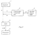
- a scanner 1 scans a document or an image and produces gray-level data in the form of e.g. data signals.
- the designation G in Fig. 2 refers to a flow of gray-level values.
- M designates maximum and minimum values and G/M refers to gray-level values and maximum and minimum values interleaved with each other.
- Intensity values or gray-levels (1 byte per pixel by way of example) from a partial area of an image is read from the scanner 1 and fed through a control logic/comparator unit 3 and via FIFO 5 to a processor, GPU, 2.
- the control logic/comparator unit 3 is, by way of example, implemented in a programmable logic circuit such as LATTICE 1032.
- the processor 2 is a special processor called GPU (an ASIC) which is created by Imsys AB (Sweden). It is also possible to use other processors, e.g. any of the processors of the AMD 29K-family or the INTEL i960 processor.
- Each read partial area which suitably consists of n scan lines of the same width b as the complete image, is divided into a number of sub images which preferably are square and consist of n x n pixels.
- the control logic/comparator unit 3 which uses a special memory buffer 4 for temporary storage of temporary maximum and minimum values, calculates maximum and minimum values for each one of the sub images of the partial area based on the flow of gray-level values.
- the processor 2 which has a writable memory for micro programs and a larger working memory, receives, via FIFO 5, gray-level values that correspond to the partial area, and maximum and minimum values for each one of the sub images of the partial area, which are interleaved with the gray-level values.
- Each n:th scan line that is received is special in such a way that in this scan line there are, interleaved after each group of n pixels, a maximum value and a minimum value for the sub image that was completed by the n preceding pixels.
- This data flow is received by the processor 2 and the gray-level values for the partial area are stored in one part of the processor 2 working memory which will act as a first cyclical buffer.
- the maximum and minimum values for each one of the sub images of the partial area are extracted and stored in another part of the processor working memory which will act as a second cyclical buffer.
- the first cyclical buffer contains gray-levels of pixels corresponding to two partial areas, i.e. 2 x b x n bytes.
- the second cyclical buffer contains maximum and minimum values, hereinafter referred to as pairs of values, for sub images corresponding to three partial areas.
- a threshold value is calculated based on the pairs of values of the sub image and a number of sub images that are adjacent to the sub image.
- the threshold value is calculated, preferably by a micro program routine written in the memory for micro programs of the processor 2, as a weighted average value of the greatest of the maximum values of the sub image and a number of sub images that are adjacent the sub image and the smallest of the minimum values of the sub image and a number of sub images that are adjacent the sub image.
- Yet another partial area is read and fed through the control logic/comparator unit 3 to produce a flow of data that is composed of gray-level values and pairs of values.
- the gray-level values for the partial area that was read first which are stored in the first cyclical buffer are written over by the gray-level values of the partial area that was read last, and pairs of values for sub images corresponding to this further partial area are stored in the second cyclical buffer.
- a threshold value is calculated based on the pairs of values of the sub image and of a number of sub images that are adjacent the sub image.
- the gray-level of each pixel of the sub image is compared with the threshold value of the sub image for transforming the pixel to either a white or a black pixel.
- the gray-levels of the partial area that was stored first in the first cyclical buffer are written over.
- the pairs of values that are stored first in the second cyclical buffer and which correspond to a complete partial area are written over.
- gray-level values, stored in the first buffer, corresponding to the two partial areas that were read last and pairs of values, stored in the second buffer, for sub images that correspond to the three partial areas that were read last are accessible.
- a threshold value is calculated, for each sub image that belongs to the partial area that was read before the last one, and each pixel of the sub image is transformed, immediately after the threshold value calculation for the respective sub image, to a white or a black pixel by comparing the gray-level of the pixels with the threshold value of the sub image.
- the steps described above are repeated until the complete gray-level image has been transformed into a black-and-white image.
- the units included in the device according to Fig. 2 are mainly conventional units or composed of conventional electronic equipment.
- the transformation of the pixels of the sub images is executed only after a threshold value has been calculated for all sub images that belong to a complete partial area by temporarily storing the threshold values in a further memory area.
- the necessary memory area can be reduced and the further memory area for storing threshold values avoided.
- this pair of values corresponds to a sub image that lies adjacent to the sub image for which the threshold value was most recently calculated, but is not adjacent any of the following central sub images. It is because of this the pair of values is no longer needed for the threshold value calculation which is based on a sub image and the pairs of values of sub images that lie adjacent to the sub image. Hence, for natural reasons, the pair of values, or more precisely, one of its two values, can be written over by the just calculated threshold value.
- threshold values are calculated and stored, for each one of the central sub images belonging to the partial area that was read before the last one.
- the transformation of each pixel in these sub images is performed by comparing the gray-level of the pixels of a sub image with the threshold value of the respective sub image.
- this transformation is executed in parallel with the reading/reception and the storage of gray-levels and pairs of values for a new partial area.
- the first cyclical buffer contains e.g. gray-levels of pixels corresponding to three partial areas, i.e. 3 x b x n bytes, whereby the reading, which is parallel to the transformation, of gray-levels for new scan lines can be executed faster than the transformation itself.
- the sub images on the edge and in the corners are advantageously transformed by a so called static threshold method, the gray-levels of the pixels in these sub images being compared with a fixed threshold value. Successive partial areas are processed correspondingly until a complete image has been transformed.
Landscapes
- Engineering & Computer Science (AREA)
- Multimedia (AREA)
- Signal Processing (AREA)
- Image Processing (AREA)
- Facsimile Image Signal Circuits (AREA)
Claims (16)
- Verfahren zur Umwandlung eines in Pixel unterteilten Grauwertbildes in ein Schwarz/Weiß-Bild mit den Schritten:das Grauwertbild wird in eine Anzahl allgemein quadratischer, sich nicht überlappender Teilbilder zerlegt, deren jedes mehr als ein Pixel enthält;für jedes der Teilbilder wird mindestens ein Meßwert berechnet und gespeichert, welcher den Grauwert des Teilbildes darstellt;für jedes der Teilbilder wird ein Schwellwert aufgrund der Meßwerte des Teilbildes und einer Anzahl dieses umgebender Teilbilder berechnet;für jedes der Teilbilder wird jedes Pixel im Teilbild entweder in ein schwarzes oder ein weißes Pixel umgewandelt, je nachdem, ob der Grauwert des Pixels den Schwellwert des Teilbildes überschreitet oder nicht.
- Verfahren nach Anspruch 1, bei welchem das in Pixel unterteilte Grauwertbild durch einen Scanner oder etwas Äquivalentes gelesen wird.
- Verfahren nach Anspruch 1 oder 2, bei welchem mindestens ein Teil des Grauwertbildes zeitweilig in einem Pufferspeicher gespeichert wird.
- Verfahren nach einem der vorstehenden Ansprüche, bei welchem mindestens ein Meßwert, der für jedes Teilbild berechnet ist und dessen Grauwert darstellt, vorübergehend in einem Pufferspeicher gespeichert wird.
- Verfahren nach einem der vorstehenden Ansprüche mit dem weiteren Schritt der Speicherung des berechneten Schwellwertes für jedes der Teilbilder.
- Verfahren nach einem der vorstehenden Ansprüche, bei welchem für mindestens eines der Teilbilder der berechnete Schwellwert vorübergehend in einem Pufferspeicher gespeichert wird.
- Verfahren nach einem der vorstehenden Ansprüche, bei welchem für mindestens eines der Teilbilder die für die Berechnung des Schwellwertes benutzten Teilbilder eine allgemein quadratische Matrix von Teilbildern bilden.
- Verfahren nach einem der vorstehenden Ansprüche, bei welchem für jedes der Teilbilder zwei Meßwerte berechnet werden.
- Verfahren nach einem der vorstehenden Ansprüche, bei welchem die Meßwertberechnung den Schritt der Erstellung eines Histogramms für jedes der Teilbilder aufgrund der Graupegel der Pixel in dem Teilbild umfaßt.
- Verfahren nach Anspruch 8, bei welchem für jedes der Teilbilder ein Maximalwert und ein Minimalwert aufgrund der Grauwerte der Pixel in dem Teilbild berechnet werden.
- Verfahren nach einem der vorstehenden Ansprüche, bei welchem Meßwerte für eine weitere Anzahl von Teilbildern, die neben denjenigen Teilbildern liegen, die dem Teilbild benachbart sind, für die Schwellwertberechnung in Betracht gezogen werden.
- Verfahren nach Anspruch 10, bei welchem der Schwellwert berechnet wird als Mittelwert aus dem größten der Maximalwerte des Teilbildes und einer Anzahl von diesem benachbarten Teilbildern und aus dem kleinsten der Minimalwerte des Teilbildes und einer Anzahl diesem benachbarter Teilbilder.
- Verfahren nach Anspruch 10, bei welchem der Schwellwert berechnet wird als gewichteter Mittelwert aus dem größten der Maximalwerte des Teilbildes und einer Anzahl von diesem benachbarter Teilbilder und dem kleinsten der Minimalwerte des Teilbildes und einer Anzahl von diesem benachbarten Teilbildern.
- Verfahren nach Anspruch 12 oder 13, bei welchem, falls die Differenz zwischen dem größten der Maximalwerte und dem kleinsten der Minimalwerte kleiner als eine bestimmte Konstante ist, der Schwellwert auf Grundlage von Schwellwerten für eine Anzahl benachbarter Teilbilder berechnet wird oder einem konstanten Wert zugeordnet wird.
- Verfahren nach einem der vorstehenden Ansprüche, bei welchem alle Teilbilder gleich groß sind.
- Verfahren zur Umwandlung eines in Pixel unterteilten Grauwertbildes in ein Schwarz/Weiß-Bild mit den Schritten:das Grauwertbild wird in eine Anzahl allgemein quadratischer und sich nicht überlappender Teilbilder unterteilt, die gegenseitig so angeordnet sind, daß sie das Grauwertbild abdecken, wobei jedes der Teilbilder mehr als ein Pixel aufweist;für jedes der Teilbilder wird ein erster Maximalwert und ein erster Minimalwert aufgrund der Grauwerte der Pixel des Teilbildes berechnet;für jedes der Teilbilder wird ein Schwellwert berechnet durchBestimmung eines primären Maximalwertes aus den ersten Maximalwerten der Teilbilder und einer Anzahl diesem benachbarter Teilbilder;Bestimmung eines primären Minimalwertes aus den ersten Minimalwerten des Teilbildes und einer Anzahl diesem benachbarter Teilbilder;Berechnung eines gewichteten Mittelwertes der primären Maximalwerte und der primären Minimalwerte als der Schwellwert; undUmwandlung jedes Pixels in dem Teilbild in entweder ein schwarzes oder ein weißes Pixel, je nachdem, ob der Grauwert des Pixels den Schwellwert des Teilbildes übersteigt oder nicht, für jedes der Teilbilder.
Applications Claiming Priority (3)
| Application Number | Priority Date | Filing Date | Title |
|---|---|---|---|
| SE9500975 | 1995-03-20 | ||
| SE9500975A SE506145C2 (sv) | 1995-03-20 | 1995-03-20 | Förfarande för omvandling av en i bildelement uppdelad gråskalebild till en svart-vit bild |
| PCT/SE1996/000347 WO1996029676A1 (en) | 1995-03-20 | 1996-03-19 | A method for transforming a gray-level image into a black-and-white image |
Publications (2)
| Publication Number | Publication Date |
|---|---|
| EP0870276A1 EP0870276A1 (de) | 1998-10-14 |
| EP0870276B1 true EP0870276B1 (de) | 2001-05-23 |
Family
ID=20397594
Family Applications (1)
| Application Number | Title | Priority Date | Filing Date |
|---|---|---|---|
| EP96907846A Expired - Lifetime EP0870276B1 (de) | 1995-03-20 | 1996-03-19 | Verfahren zum umsetzen eines grautonbildes in ein schwarz-weiss-bild |
Country Status (5)
| Country | Link |
|---|---|
| US (1) | US6014465A (de) |
| EP (1) | EP0870276B1 (de) |
| DE (1) | DE69613002T2 (de) |
| SE (1) | SE506145C2 (de) |
| WO (1) | WO1996029676A1 (de) |
Families Citing this family (7)
| Publication number | Priority date | Publication date | Assignee | Title |
|---|---|---|---|---|
| DE19717814B4 (de) * | 1997-04-26 | 2008-06-05 | Klaus Prof. Dr. Wevelsiep | Verfahren zur Segmentierung von Schriftzeichen und Symbolen auf Kfz-Kennzeichenschildern und formatierten Datenträgern sowie zur Segmentierung von Mustern in komplexen Szenen |
| US6401054B1 (en) * | 1998-12-28 | 2002-06-04 | General Electric Company | Method of statistical analysis in an intelligent electronic device |
| US6836396B1 (en) | 2000-09-13 | 2004-12-28 | General Electric Company | World wide web enabled and digital rating plug |
| US8224723B2 (en) | 2002-05-31 | 2012-07-17 | Jpmorgan Chase Bank, N.A. | Account opening system, method and computer program product |
| US20040080789A1 (en) * | 2002-10-28 | 2004-04-29 | Anderson James E. | Gray scale enhancements for color documents rendered on monochrome devices |
| JP2006098217A (ja) * | 2004-09-29 | 2006-04-13 | Fujitsu Ltd | 画像検査装置、画像検査方法及び画像検査プログラム |
| KR101811792B1 (ko) | 2011-03-14 | 2017-12-22 | 루브리졸 어드밴스드 머티어리얼스, 인코포레이티드 | 폴리머 및 이의 조성물 |
Family Cites Families (5)
| Publication number | Priority date | Publication date | Assignee | Title |
|---|---|---|---|---|
| AU565874B2 (en) * | 1983-03-11 | 1987-10-01 | Ei Solutions, Inc. | Adaptive threshold circuit for digital image processing |
| JPS6173477A (ja) * | 1984-09-19 | 1986-04-15 | Minolta Camera Co Ltd | 画像処理方法 |
| US4903316A (en) * | 1986-05-16 | 1990-02-20 | Fuji Electric Co., Ltd. | Binarizing apparatus |
| US5608814A (en) * | 1993-08-26 | 1997-03-04 | General Electric Company | Method of dynamic thresholding for flaw detection in ultrasonic C-scan images |
| KR0136067B1 (ko) * | 1994-08-12 | 1998-04-27 | 김광호 | 이치화상 프로세서 |
-
1995
- 1995-03-20 SE SE9500975A patent/SE506145C2/sv not_active IP Right Cessation
-
1996
- 1996-03-19 DE DE69613002T patent/DE69613002T2/de not_active Expired - Lifetime
- 1996-03-19 WO PCT/SE1996/000347 patent/WO1996029676A1/en active IP Right Grant
- 1996-03-19 US US08/913,415 patent/US6014465A/en not_active Expired - Lifetime
- 1996-03-19 EP EP96907846A patent/EP0870276B1/de not_active Expired - Lifetime
Also Published As
| Publication number | Publication date |
|---|---|
| DE69613002T2 (de) | 2002-01-31 |
| WO1996029676A1 (en) | 1996-09-26 |
| US6014465A (en) | 2000-01-11 |
| DE69613002D1 (de) | 2001-06-28 |
| SE9500975D0 (sv) | 1995-03-20 |
| EP0870276A1 (de) | 1998-10-14 |
| SE9500975L (sv) | 1996-09-21 |
| SE506145C2 (sv) | 1997-11-17 |
Similar Documents
| Publication | Publication Date | Title |
|---|---|---|
| US5568571A (en) | Image enhancement system | |
| US5563403A (en) | Method and apparatus for detection of a skew angle of a document image using a regression coefficient | |
| EP1173003B1 (de) | Bildverarbeitungsverfahren und Bildverarbeitungsvorrichtung | |
| US5280367A (en) | Automatic separation of text from background in scanned images of complex documents | |
| US6393150B1 (en) | Region-based image binarization system | |
| EP0713329A1 (de) | Verfahren und Vorrichtung zur automatischen Bildsegmentierung unter Verwendung von Standardvergleichsmustern | |
| US7437002B2 (en) | Image recognition system utilizing an edge image and a binary image | |
| JP4339925B2 (ja) | 文書画像処理方法、文書画像処理装置、文書画像処理プログラムおよび記憶媒体 | |
| EP0870276B1 (de) | Verfahren zum umsetzen eines grautonbildes in ein schwarz-weiss-bild | |
| US6289122B1 (en) | Intelligent detection of text on a page | |
| JPH0879517A (ja) | 画像の型を識別する方法 | |
| JP3073837B2 (ja) | 画像領域分離装置及び画像領域分離方法 | |
| EP0600613A2 (de) | Bildverarbeitungsverfahren und Vorrichtung | |
| KR100537827B1 (ko) | 경계선 분포를 이용한 스캔 영상의 상역 분리 방법 | |
| JP2972500B2 (ja) | 解像度適応制御装置 | |
| JPH1098613A (ja) | 画像処理装置 | |
| JP3358133B2 (ja) | 画像処理装置 | |
| JP2877548B2 (ja) | 文書画像の属性判別方法 | |
| JPH1098614A (ja) | 画像処理装置 | |
| JP2937603B2 (ja) | 画像データ読み取り装置における画像データの2値化判別方法 | |
| JPH08221515A (ja) | 画像処理装置 | |
| JPH04290177A (ja) | 多階調画像情報の2値化処理方法 | |
| JPH08251403A (ja) | 画像領域属性判別装置 | |
| KR100229028B1 (ko) | 연속성에 따른 이치화방법 | |
| JP3146516B2 (ja) | 画像処理装置 |
Legal Events
| Date | Code | Title | Description |
|---|---|---|---|
| PUAI | Public reference made under article 153(3) epc to a published international application that has entered the european phase |
Free format text: ORIGINAL CODE: 0009012 |
|
| 17P | Request for examination filed |
Effective date: 19971006 |
|
| AK | Designated contracting states |
Kind code of ref document: A1 Designated state(s): DE FR GB IT NL |
|
| GRAG | Despatch of communication of intention to grant |
Free format text: ORIGINAL CODE: EPIDOS AGRA |
|
| GRAG | Despatch of communication of intention to grant |
Free format text: ORIGINAL CODE: EPIDOS AGRA |
|
| GRAG | Despatch of communication of intention to grant |
Free format text: ORIGINAL CODE: EPIDOS AGRA |
|
| GRAH | Despatch of communication of intention to grant a patent |
Free format text: ORIGINAL CODE: EPIDOS IGRA |
|
| 17Q | First examination report despatched |
Effective date: 20001030 |
|
| GRAH | Despatch of communication of intention to grant a patent |
Free format text: ORIGINAL CODE: EPIDOS IGRA |
|
| GRAA | (expected) grant |
Free format text: ORIGINAL CODE: 0009210 |
|
| AK | Designated contracting states |
Kind code of ref document: B1 Designated state(s): DE FR GB IT NL |
|
| PG25 | Lapsed in a contracting state [announced via postgrant information from national office to epo] |
Ref country code: NL Free format text: LAPSE BECAUSE OF FAILURE TO SUBMIT A TRANSLATION OF THE DESCRIPTION OR TO PAY THE FEE WITHIN THE PRESCRIBED TIME-LIMIT Effective date: 20010523 Ref country code: IT Free format text: LAPSE BECAUSE OF FAILURE TO SUBMIT A TRANSLATION OF THE DESCRIPTION OR TO PAY THE FEE WITHIN THE PRESCRIBED TIME-LIMIT;WARNING: LAPSES OF ITALIAN PATENTS WITH EFFECTIVE DATE BEFORE 2007 MAY HAVE OCCURRED AT ANY TIME BEFORE 2007. THE CORRECT EFFECTIVE DATE MAY BE DIFFERENT FROM THE ONE RECORDED. Effective date: 20010523 |
|
| REF | Corresponds to: |
Ref document number: 69613002 Country of ref document: DE Date of ref document: 20010628 |
|
| ET | Fr: translation filed | ||
| NLV1 | Nl: lapsed or annulled due to failure to fulfill the requirements of art. 29p and 29m of the patents act | ||
| REG | Reference to a national code |
Ref country code: GB Ref legal event code: IF02 |
|
| PLBE | No opposition filed within time limit |
Free format text: ORIGINAL CODE: 0009261 |
|
| STAA | Information on the status of an ep patent application or granted ep patent |
Free format text: STATUS: NO OPPOSITION FILED WITHIN TIME LIMIT |
|
| 26N | No opposition filed | ||
| REG | Reference to a national code |
Ref country code: FR Ref legal event code: PLFP Year of fee payment: 20 |
|
| PGFP | Annual fee paid to national office [announced via postgrant information from national office to epo] |
Ref country code: FR Payment date: 20150224 Year of fee payment: 20 Ref country code: GB Payment date: 20150224 Year of fee payment: 20 |
|
| PGFP | Annual fee paid to national office [announced via postgrant information from national office to epo] |
Ref country code: DE Payment date: 20150331 Year of fee payment: 20 |
|
| REG | Reference to a national code |
Ref country code: DE Ref legal event code: R071 Ref document number: 69613002 Country of ref document: DE |
|
| REG | Reference to a national code |
Ref country code: GB Ref legal event code: PE20 Expiry date: 20160318 |
|
| PG25 | Lapsed in a contracting state [announced via postgrant information from national office to epo] |
Ref country code: GB Free format text: LAPSE BECAUSE OF EXPIRATION OF PROTECTION Effective date: 20160318 |