EP0803755B1 - Projection optical system and exposure apparatus with the same - Google Patents
Projection optical system and exposure apparatus with the same Download PDFInfo
- Publication number
- EP0803755B1 EP0803755B1 EP96108775A EP96108775A EP0803755B1 EP 0803755 B1 EP0803755 B1 EP 0803755B1 EP 96108775 A EP96108775 A EP 96108775A EP 96108775 A EP96108775 A EP 96108775A EP 0803755 B1 EP0803755 B1 EP 0803755B1
- Authority
- EP
- European Patent Office
- Prior art keywords
- lens
- lens group
- optical system
- projection optical
- negative
- Prior art date
- Legal status (The legal status is an assumption and is not a legal conclusion. Google has not performed a legal analysis and makes no representation as to the accuracy of the status listed.)
- Revoked
Links
- 230000003287 optical effect Effects 0.000 title claims description 159
- 239000000758 substrate Substances 0.000 claims description 25
- 238000005286 illumination Methods 0.000 claims description 21
- 230000004075 alteration Effects 0.000 description 45
- 206010010071 Coma Diseases 0.000 description 30
- 230000005499 meniscus Effects 0.000 description 25
- 238000010586 diagram Methods 0.000 description 18
- 201000009310 astigmatism Diseases 0.000 description 8
- 210000001747 pupil Anatomy 0.000 description 8
- 230000007423 decrease Effects 0.000 description 5
- 239000011521 glass Substances 0.000 description 5
- 239000000463 material Substances 0.000 description 5
- QSHDDOUJBYECFT-UHFFFAOYSA-N mercury Chemical compound [Hg] QSHDDOUJBYECFT-UHFFFAOYSA-N 0.000 description 4
- 229910052753 mercury Inorganic materials 0.000 description 4
- XUIMIQQOPSSXEZ-UHFFFAOYSA-N Silicon Chemical compound [Si] XUIMIQQOPSSXEZ-UHFFFAOYSA-N 0.000 description 3
- 229910052710 silicon Inorganic materials 0.000 description 3
- 239000010703 silicon Substances 0.000 description 3
- 230000007246 mechanism Effects 0.000 description 2
- 238000012986 modification Methods 0.000 description 2
- 230000004048 modification Effects 0.000 description 2
- 230000004304 visual acuity Effects 0.000 description 2
- 206010034972 Photosensitivity reaction Diseases 0.000 description 1
- VYPSYNLAJGMNEJ-UHFFFAOYSA-N Silicium dioxide Chemical compound O=[Si]=O VYPSYNLAJGMNEJ-UHFFFAOYSA-N 0.000 description 1
- 230000008859 change Effects 0.000 description 1
- 239000011248 coating agent Substances 0.000 description 1
- 238000000576 coating method Methods 0.000 description 1
- 230000002542 deteriorative effect Effects 0.000 description 1
- 230000002349 favourable effect Effects 0.000 description 1
- 239000004973 liquid crystal related substance Substances 0.000 description 1
- 229920002120 photoresistant polymer Polymers 0.000 description 1
- 230000036211 photosensitivity Effects 0.000 description 1
- 239000004065 semiconductor Substances 0.000 description 1
Images


Classifications
-
- G—PHYSICS
- G03—PHOTOGRAPHY; CINEMATOGRAPHY; ANALOGOUS TECHNIQUES USING WAVES OTHER THAN OPTICAL WAVES; ELECTROGRAPHY; HOLOGRAPHY
- G03F—PHOTOMECHANICAL PRODUCTION OF TEXTURED OR PATTERNED SURFACES, e.g. FOR PRINTING, FOR PROCESSING OF SEMICONDUCTOR DEVICES; MATERIALS THEREFOR; ORIGINALS THEREFOR; APPARATUS SPECIALLY ADAPTED THEREFOR
- G03F7/00—Photomechanical, e.g. photolithographic, production of textured or patterned surfaces, e.g. printing surfaces; Materials therefor, e.g. comprising photoresists; Apparatus specially adapted therefor
- G03F7/20—Exposure; Apparatus therefor
-
- G—PHYSICS
- G03—PHOTOGRAPHY; CINEMATOGRAPHY; ANALOGOUS TECHNIQUES USING WAVES OTHER THAN OPTICAL WAVES; ELECTROGRAPHY; HOLOGRAPHY
- G03F—PHOTOMECHANICAL PRODUCTION OF TEXTURED OR PATTERNED SURFACES, e.g. FOR PRINTING, FOR PROCESSING OF SEMICONDUCTOR DEVICES; MATERIALS THEREFOR; ORIGINALS THEREFOR; APPARATUS SPECIALLY ADAPTED THEREFOR
- G03F7/00—Photomechanical, e.g. photolithographic, production of textured or patterned surfaces, e.g. printing surfaces; Materials therefor, e.g. comprising photoresists; Apparatus specially adapted therefor
- G03F7/70—Microphotolithographic exposure; Apparatus therefor
- G03F7/70216—Mask projection systems
-
- G—PHYSICS
- G02—OPTICS
- G02B—OPTICAL ELEMENTS, SYSTEMS OR APPARATUS
- G02B13/00—Optical objectives specially designed for the purposes specified below
- G02B13/22—Telecentric objectives or lens systems
Definitions
- the present invention relates to a projection optical system for projecting an image of a pattern on a first object onto a substrate or the like as a second object. More particularly, the invention concerns a projection optical system suitably applicable for projection-exposing a pattern for semiconductor or for liquid crystal formed on a reticle (or mask) as a first object onto a substrate (silicon wafer, glass plate, or the like) as a second object.
- a light source for exposure is changing recently from one for emitting light of exposure wavelength of the g-line (436 nm) to one for emitting light of exposure wavelength of the i-line (365 nm), which is mainly used these years. Further, light sources for emitting light of further shorter wavelengths, for example excimer lasers (248 nm, 193 nm), are being used as a light source for exposure.
- the projection optical systems are demanded to decrease image distortion as well as to improve the resolving power.
- the image distortion is caused by distortion due to the projection optical system, warpage of the wafer to be printed on the image side of projection optical system, warpage of the reticle with circuit patterns or the like. written thereon on the object side of projection optical system, or the like.
- both-side telecentric projection optical systems in which both object side (reticle side) and image side (substrate side) are telecentric, are disclosed.
- N.A. numerical aperture
- the object of the present invention is to provide a high-performance both-side telecentric projection optical system which has a compact structure while securing a broad exposure area and a large numerical aperture as well as an exposure apparatus equipped with such a projection optical system.
- this projection optical system has a structure which can quite favorably correct various kinds of aberration such as distortion in particular.
- a one-shot exposure type exposure apparatus or a scanning type exposure apparatus in which a mask and a substrate are relatively movable with respect to the projection optical system, has been known in general.
- the exposure apparatus comprises, at least, a first stage allowing a mask (first object) having a predetermined pattern such as an integrated circuit to be held on a main surface thereof; a second stage capable of holding, on its main surface, a photosensitive substrate (second object) upon which the pattern of the mask is to be printed; an illumination optical system for illuminating the mask with exposure light having a predetermined wavelength; and a projection optical system provided between the first and second stages and used for projecting the predetermined pattern on the mask onto the substrate.
- photosensitive substrate refers to a substrate such as silicon wafer or glass plate whose surface is coated with a material such as resist having a photosensitivity with respect to the exposure light.
- the exposure apparatus comprises a first lens group G 1 with a positive refracting power provided between the above-mentioned first object R and second object W, a second lens group G 2 with a negative refracting power provided between the first lens group G 1 and the second object W, a third lens group G 3 with a positing refracting power provided between the second lens group G 2 and the second object W, a fourth lens group G 4 with a negative refracting power provided between the third lens group G 3 and the second object W, a fifth lens group G 5 with a positive refracting power provided between the fourth lens group G 4 and the second object W, and a sixth lens group G 6 with a positive refracting power provided between the fifth lens group G 5 and the second object W.
- the first lens group G 1 having a positive refracting power mainly contributes to correction of distortion while maintaining telecentricity. Specifically, the first lens group G 1 generates positive distortion so as to correct, in a well-balanced manner, negative distortion generated by a plurality of the lens groups placed between the first lens group G 1 and the second object W.
- the second lens group G 2 having a negative refracting power and the fourth lens group G 4 having a negative refracting power mainly contribute to correction of Petzval sum in order to flatten the image surface.
- the second lens group G 2 having a negative refracting power and the third lens group G 3 having a positive refracting power constitute an inverted telescopic system.
- This inverted telescopic system partakes in securing backfocus of the projection optical system (distance from the optical surface such as a lens surface which is closest to the second object in the projection optical system to the second object W).
- these lens groups G 5 and G 6 function to minimize generation of spherical aberration in order to sufficiently respond to a higher N.A. on the second object side.
- the above-mentioned second lens group G 2 comprises a front lens L 2F with a negative refracting power located as closest to the first object R and shaped with a concave surface to the second object W, a rear lens L 2R with a negative refracting power located as closest to the second object W and shaped with a concave surface to the first object R, and an intermediate lens group G 2M placed between the front lens L 2F and the rear lens L 2R .
- the front lens L 2F with a negative refracting power which is located as closest to the first object R and shaped with a concave surface to the second object W, contributes to correction of curvature of field and coma
- the rear lens L 2R with a negative refracting power which is located as closest to the second object W and shaped with a concave surface to the first object R, mainly contributes to correction of coma.
- the rear lens L 2R also contributes to correction of curvature of field.
- the above-described intermediate lens group G 2M comprises a first intermediate lens L M1 with a positive refracting power placed between the front lens L 2F and the rear lens L 2R , a second intermediate lens L M2 with a negative refracting power placed between the first intermediate lens L M1 and the rear lens L 2R , and a third intermediate lens L M3 with a negative refracting power placed between the second intermediate lens L M2 and the rear lens L 2R .
- the first intermediate lens L M1 having a positive refracting power partakes in correction of negative distortion generated by the second and third intermediate lenses L M2 and L M3 which greatly contribute to correction of curvature of field.
- the focal length of the first lens group G 1 is f 1
- the focal length of the second lens group G 2 is f 2
- the focal length of the third lens group G 3 is f 3
- the focal length of the fourth lens group G 4 is f 4
- the focal length of the fifth lens group G 5 is f 5
- the focal length of the sixth lens group G 6 is f 6
- the distance from the first object R to the second object W is L
- the radius of curvature of the surface of the front lens L 2F on the first object side is r 2Ff
- the radius of curvature of the surface of the front lens L 2F on the second object side is r 2Fr
- the radius of curvature of the surface of the rear lens L 2R on the first object side is r 2Rf
- the radius of curvature of the surface of the rear lens L 2R on the second object side is r 2Rr
- the projection optical system of the present invention satisfies the following conditions (1) to (8):
- the condition (1) defines an optimal ratio of the focal length f 1 of the first lens group G 1 having a positive refracting power to the distance (object-to-image distance) L from the first object R (reticle or the like) to the second object W (wafer or the like). This is a condition for mainly correcting distortion in a well-balanced manner.
- the upper limit of the ratio in the condition (1) is set to 0.14 so as to define a condition of f 1 /L ⁇ 0.14.
- the lower limit of the ratio in the condition (1) is set to 0.02 so as to define a condition of 0.02 ⁇ f 1 /L.
- the condition (2) defines an optimal ratio of the focal length f 2 of the second lens group G 2 having a negative refracting power to the distance (object-to-image distance) L from the first object R (reticle or the like) to the second object W (wafer or the like). This is a condition for attaining a compact size while securing a broad exposure area and effectively correcting Petzval sum.
- the lower limit of the ratio in the condition (2) is set to -0.032 so as to define a condition of -0.032 ⁇ f 2 /L.
- the upper limit of the ratio in the condition (2) is set to -0.005 so as to define a condition of f 2 /L ⁇ -0.005.
- the condition (3) defines an optimal ratio of the focal length f 3 of the third lens group G 3 having a positive refracting power to the distance (object-to-image distance) L from the first object R (reticle or the like) to the second object W (wafer or the like).
- the refractive power of the second lens group G 2 or fourth lens group G 4 becomes too strong.
- negative distortion and coma may occur in the second lens group G 2
- coma may occur in the fourth lens group G 4 .
- the refractive power of the second lens group G 2 or fourth lens group G 4 becomes so weak that Petzval sum may not be effectively corrected.
- the condition (4) defines an optimal ratio of the focal length f 4 of the fourth lens group G 4 having a negative refracting power to the distance (object-to-image distance) L from the first object R (reticle or the like) to the second object W (wafer or the like).
- the upper limit of the ratio in the condition (4) is set to -0.047 so as to define a condition of f 4 /L ⁇ -0.047.
- the lower limit of the ratio in the condition (4) is set to -0.098 so as to define a condition of -0.098(f 4 /L.
- the condition (5) defines an optimal ratio of the focal length f 5 of the fifth lens group G 5 having a positive refracting power to the distance (object-to-image distance) L from the first object R (reticle or the like) to the second object W (wafer or the like). This is a condition for correcting spherical aberration, distortion, and Petzval sum in a well-balanced manner while maintaining a large numerical aperture.
- the refractive power of the fifth lens group G 5 becomes too strong. As a result, not only negative distortion but an enormous amount of negative spherical aberration may be generated in the fifth lens group G 5 .
- the refractive power of the fifth lens group G 5 becomes so weak that the refractive power of the fourth lens group G 4 inevitably decreases. As a result, Petzval sum may not be corrected effectively.
- the condition (6) defines an optimal ratio of the focal length f 6 of the sixth lens group G 6 having a positive refracting power to the distance (object-to-image distance) L from the first object R (reticle or the like) to the second object W (wafer or the like). This is a condition for suppressing generation of high-order spherical aberration and negative distortion, while maintaining a large numerical aperture. Below the lower limit of the ratio defined by the condition (6), the sixth lens group G 6 itself may generate a large amount of negative distortion. Above the upper limit of the ratio defined by the condition (6), on the other hand, high-order spherical aberration may occur.
- the condition (7) defines a so-called shape factor to obtain an appropriate shape of the front lens L 2F in the second lens group G 2 when the radius of curvature of the surface of the front lens L 2F on the first object side is r 2Ff and the radius of curvature of the surface of the front lens L 2F on the second object side is r 2Fr .
- the condition (8) defines a so-called shape factor to obtain an appropriate shape of the rear lens L 2R in the second lens group G 2 when the radius of curvature of the surface of the rear lens L 2R on the first object side is r 2Rf and the radius of curvature of the surface of the rear lens L 2R on the second object side is r 2Rr .
- r 2Rf the radius of curvature of the surface of the rear lens L 2R on the first object side
- r 2Rrr the radius of curvature of the surface of the rear lens L 2R on the second object side
- the lower limit of the ratio in the condition (8) is set to -5.0 so as to define a condition of -5.0 ⁇ (r 2Rf -r 2Rr )/(r 2Rf +r 2Rr ).
- the lower limit of the ratio in the condition (8) is preferably set to -2.0 so as to define a condition of -2.0 ⁇ (r 2Rf -r 2Rr )/( r 2Rf +r 2Rr ).
- the projection optical system preferably satisfies the following condition (9):
- the condition (9) defines an optimal ratio of the axial distance I from the first object R to the first-object-side focal point of the entire projection optical system to the distance (object-to-image distance) L from the first object R (reticle or the like) to the second object W (wafer or the like).
- first-object-side focal point of the entire projection optical system refers to an intersecting point of emergent light with an optical axis of the projection optical system when parallel light in the paraxial region with respect to the optical axis of the projection optical system is made incident from the second object side of the projection optical system and the light in the paraxial region is emergent from the projection optical system.
- the lower limit of the ratio in the condition (9) is set to 1.7 so as to define a condition of 1.7 ⁇ I/L.
- the upper limit of the ratio in the condition (9) is preferably set to 6.8 so as to define a condition of I/L ⁇ 6.8.
- the above-mentioned fifth lens group G 5 includes at least seven positive lenses.
- the fifth lens group G 5 further includes at least one negative lens.
- the refractive power carried by the fifth lens group G 5 itself can be distributed to the separate positive lenses in a well-balanced manner. Accordingly, negative spherical aberration which is likely to occur in the fifth lens group G 5 as its numerical aperture (N.A.) increases can be effectively suppressed. Further, when the fifth lens group G 5 has at least seven positive lenses, high resolution of the projection optical system is secured.
- the fifth lens group G 5 preferably has at least one negative lens in addition to at least seven positive lenses.
- the projection optical system satisfies the following condition (10):
- the refractive power of the second intermediate lens L M2 becomes stronger than that of the third intermediate lens L M3 .
- the lower limit of the ratio in the condition (10) is set to 0.7 so as to define a condition of 0.7 ⁇ f 22 /f 23 .
- the refractive power of the third intermediate lens L M3 becomes stronger than that of the second intermediate lens L M2 . Accordingly, a large amount of coma and negative distortion is generated in the third intermediate lens L M3 .
- the upper limit of the ratio in the condition (10) is preferably set to 1.5 so as to define a condition of f 22 /f 23 ⁇ 1.5.
- the above-mentioned fifth lens group G 5 has a negative lens L 59 located as closest to the second object W and shaped with a concave surface to the second object W. Accordingly, the negative lens L 59 located as closest to the second object W in the fifth lens group G 5 can generate positive distortion and negative Petzval sum. This means that the negative distortion and positive Petzval sum generated by the positive lenses in the fifth lens group G 5 can be offset thereby.
- a lens L 61 positioned as closest to the first object R in the sixth lens group G 6 preferably has such a shape that its lens surface on the first object side is a convex surface facing the first object R.
- the projection optical system preferably satisfies the following condition (11):
- the condition (11) defines an optimal form of a gas lens formed between the fifth lens group G 5 and the sixth lens G 6 .
- the curvature of the concave surface on the second object side of the negative lens L 59 positioned as closest to the second object W in the fifth lens group G 5 becomes too strong. Under this circumstance, high-order coma may occur.
- the inherent refractive power of the gas lens formed between the fifth lens group G 5 and the sixth lens G 6 becomes too weak. As a result, the amount of positive distortion generated in this gas lens becomes so small that it becomes difficult to effectively correct negative distortion generated in the positive lenses in the fifth lens group G 5 .
- the lower limit of the ratio in the condition (11) is preferably set to -0.30 so as to define a condition of -0.30 ⁇ (r 5R -r 6F )/(r 5R +r 6F ).
- the projection optical system preferably satisfies the following condition (12):
- the lens group distance between the fifth lens group G 5 and the sixth lens group G 6 becomes so large that the amount of positive distortion generated thereby may be too small. As a result, it becomes difficult to correct, in a well-balanced manner, negative distortion generated in the positive lenses in the fifth lens group G 5 .
- the projection optical system preferably satisfies the following condition (13):
- the lower limit of the ratio in the condition (13) is set to 0.84 so as to define a condition of 0.84 ⁇ d 6 /r 6F .
- the above-mentioned fifth lens group G 5 has the negative lens L 59 located as closest to the second object W and shaped with a concave surface to the second object W.
- the projection optical system further satisfies the following condition (14):
- the upper limit of the ratio in the condition (14) is set to 0.93 so as to define a condition of (r 5F -r 5R )/(r 5F +r 5R ) ⁇ 0.93.
- the projection optical system preferably satisfies the following condition (15):
- the lens surface of the first intermediate lens L M1 on the second object side has such a lens shape that a convex surface thereof faces the second object W.
- the projection optical system preferably satisfies the following condition (16):
- the condition (16) defines an optimal ratio of the focal length f 2F of the front lens L 2F in the second lens group G 2 to the focal length f 2R of the rear lens L 2R in the second lens group G 2 .
- the refractive power of the first lens group G 1 or third lens group G 3 may lose its balance. As a result, it becomes difficult to effectively correct distortion or effectively correct both Petzval sum and astigmatism at the same time.
- the intermediate lens group G 2M in the second lens group G 2 preferably has a negative refracting power.
- the above-mentioned respective lens groups specifically have the following configurations.
- the first lens group G 1 has at least two positive lenses.
- the third lens group G 3 has at least three positive lenses.
- the fourth lens group G 4 has at least three negative lenses.
- the sixth lens group G 6 has at least one positive lens.
- the number of the negative lenses constituting the intermediate lens group G 2M in the second lens group G 2 is desirably limited to two.
- the above-mentioned sixth lens group G 6 is preferably constituted by not more than three lenses each having a lens surface which satisfies at least the following condition (17):
- the number of the lens surfaces having a certain degree of curvature disposed near the second object W unfavorably increases, thereby causing distortion to occur.
- Fig. 1 will be made reference to when necessary.
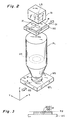
- Fig. 2 is a drawing to show the schematic setup of a scanning exposure apparatus to which the projection optical system according to the present invention can be applied.
- the reticle R (first object) as a photomask on which predetermined circuit patterns are formed is disposed on the object plane P1 of the projection optical system PL
- the wafer W (second object) as a photosensitive substrate is disposed on the image plane P2 of the projection optical system PL.
- the reticle R is held on a reticle stage RS arranged to move in the X-direction (corresponding to the arrow D1 in Fig. 2) upon exposure
- the wafer W is held on a wafer stage WS arranged to move in the X-direction (corresponding to the arrow D2 in Fig. 2) opposite to movement of the reticle stage RS.
- a slit (rectangular) illumination area IF 1 extending in the Y-direction is formed on the reticle R, and an illumination optical system IS for uniformly illuminating the illumination area IF 1 is disposed above the reticle R. Exposure light is emitted from a light source LS provided in the illumination system.
- the light supplied from the light source LS in the illumination optical system IS illuminates the reticle R in a slit pattern.
- An image of the light source LS in the illumination optical system IS is formed at the position of the pupil (the position of aperture stop AS) of the projection optical system PL, thus realizing so-called Köhler illumination.
- an image of the pattern of reticle R Köhler-illuminated is projected (or transferred) onto the wafer W through the projection optical system PL.
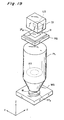
- the photosensitive substrate placed on the above wafer stage WS is one obtained by coating the entire surface of exposed object 100 such as a silicon wafer, a glass plate, or the like with a photosensitive material 200 such as a photoresist, as shown in Fig. 3.
- an area EF 1 of the pattern image of reticle R exposed on the wafer W is a slit pattern (rectangular shape) extending in the Y-direction, as shown in Fig. 2.
- the projection magnification factor of the projection optical system PL is 1/M
- the reticle stage RS and wafer stage WS are moved in mutually opposite directions (corresponding to the arrows D1 and D2, respectively) along the X-direction in the velocity ratio of M:1, thereby the pattern image of the entire surface of reticle R is transferred onto the wafer W.
- the above United States Patent Application No. 08/255,927 describes the illumination optical system (using a laser light source) applicable to the scanning exposure apparatus.
- the above United States Patent Application No. 08/260,398 describes the illumination optical system (using a lamp light source) applicable to the scanning exposure apparatus.
- the United States Patent Application No. 08/299,305 discloses an alignment mechanism applicable to the scanning exposure apparatus.
- the United States Patent No. 4,497,015 describes the illumination optical system (using a lamp light source) applicable to popular exposure apparatus.
- the United States Patent No. 4,666,273 discloses an example of the step-and-repeat type exposure apparatus.
- 5,194,893 discloses the scanning exposure apparatus, particularly, the illumination optical system, illumination area, mask-side and reticle-side interference systems, automatic focusing mechanism, and alignment optical system.
- the United States Patent No. 5,253,110 describes the illumination optical system (using a laser light source) applicable to the step-and-repeat type exposure apparatus.
- the illumination optical system disclosed in this reference can also be applied to the scanning exposure apparatus.
- the United States Patent No. 5,333,035 discloses a modified illumination optical system applicable to popular exposure apparatus.
- the United States Patent No. 5,379,091 discloses the illumination optical system (using a laser light source) applicable to the scanning exposure apparatus.
- United States Patent No. 5,245,384 also shows the illumination optical system using a mercury lamp, applicable to ordinary exposure apparatus (steppers).
- the following embodiments show examples of the projection optical system to which a high pressure mercury lamp for supplying light having the exposure wavelength ⁇ of i-line (365 nm) is applicable as a light source LS disposed inside the illumination optical system IS.
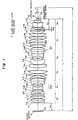
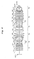
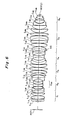
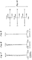
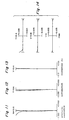
- Fig. 4 to Fig. 6 show lens layouts of the first to third embodiments of the projection optical system according to the present invention.
- the projection optical system in each lens layout is composed of, in order from the side of reticle R as a first object, the first lens group G 1 having a positive refracting power, the second lens group G 2 having a negative refracting power, the third lens group G 3 having a positive refracting power, the fourth lens group G 4 having a negative refracting power, the fifth lens group G 5 having a positive refracting power, and the sixth lens group G 6 having the positive refracting power.
- These examples of the projection optical system are approximately telecentric on the object side (on the reticle side) and on the image side (on the wafer side) thereof, and have demagnification factors.
- object-to-image distance L distance from an object surface P1 to an image surface P2 or the distance from the reticle R to the wafer W
- image-side numerical aperture NA is 0.6
- projection magnification B is 1/4
- diameter of the exposure area on the wafer W or diagonal length of the slit-like exposure area on the wafer W of the projection optical system PL is 26.7.
- the first lens group G 1 has, in order from the reticle R toward the wafer W, a negative meniscus lens L 11 whose concave surface faces the image surface P2, a positive lens (positive lens having a biconvex shape) L 12 whose stronger convex surface faces the image surface P2, and two positive lenses (positive lenses each having a biconvex shape) L 13 and L 14 whose respective stronger convex surfaces face the object surface P1.
- the second lens group G 2 has a negative lens (biconcave negative lens: front lens) L 2F which is disposed as closest to the object R (reticle) and whose stronger concave surface faces the image surface P2, a negative lens (plano-concave negative lens: rear lens) L 2R which is disposed as closest to the image W (wafer) and whose concave surface faces the object surface P1, and an intermediate lens group G 2M which is disposed between these negative lenses L 2F and L 2R and has a negative refracting power.
- a negative lens biconcave negative lens: front lens
- L 2F which is disposed as closest to the object R (reticle) and whose stronger concave surface faces the image surface P2
- a negative lens (plano-concave negative lens: rear lens) L 2R which is disposed as closest to the image W (wafer) and whose concave surface faces the object surface P1
- an intermediate lens group G 2M which is disposed between these negative lenses L 2F and
- the intermediate lens group G 2M has, in order from the reticle R toward the wafer W, a positive lens (positive biconvex lens: first lens) L M1 whose stronger convex surface faces the image surface P2, a negative lens (negative meniscus lens: second lens) L M2 whose concave surface faces the image surface P2, and a negative lens (negative biconcave lens: third lens) L M3 whose stronger concave surface faces the object surface P1.
- the third lens group G 3 has, in order from the reticle R toward the wafer W, two positive lenses (positive meniscus lenses) L 31 and L 32 whose respective convex surfaces face the image surface P2, a positive lens (positive biconvex lens) L 33 whose stronger convex surface similarly faces the image surface P2, and a positive lens (positive biconvex lens) L 34 whose stronger convex surface faces the object surface P1, and a positive lens (positive meniscus lens) L 35 whose convex surface similarly faces the object surface P1.
- the fourth lens group G 4 has, in order from the reticle R toward the wafer W, a negative lens (negative meniscus lens) L 41 whose concave surface faces the image surface P2, a negative biconcave lens L 42 , and a negative lens (negative biconcave lens) L 43 whose stronger concave surface faces the object surface P1.
- the fifth lens group G 5 has, in order from the reticle R toward the wafer W, a positive lens (positive biconvex lens) L 51 whose stronger convex surface faces the object surface P1, a positive lens (positive meniscus lens) L 52 whose convex surface faces the image surface P2, two positive lenses (positive biconvex lenses) L 53 and L 54 whose respective stronger convex surfaces similarly face the image surface P2, a negative lens (negative meniscus lens) L 55 whose concave surface faces the object surface P1, three positive lenses (positive meniscus lenses) L 56 , L 57 , and L 58 whose respective convex surfaces face the object surface P1, and a negative lens (negative meniscus lens) L 59 whose concave surface faces the image surface P2.
- a positive lens (positive biconvex lens) L 51 whose stronger convex surface faces the object surface P1
- a positive lens (positive meniscus lens) L 52 whose convex surface faces the image surface P2
- the sixth lens group G 6 has, in order from the reticle R toward the wafer W, a positive lens (positive biconvex lens) L 61 whose stronger convex surface faces the object surface P1, a negative lens (negative meniscus lens) L 62 whose concave surface faces the image surface P2, and a positive lens (positive meniscus lens) L 63 whose convex surface faces the object surface P1.
- the image-side lens surface of the negative lens (negative meniscus lens) L 11 whose concave surface faces the image surface P2
- the object-side lens surface of the positive biconvex lens L 12 have similar degrees of curvature and are relatively close to each other, these two lens surfaces correct high-order distortion.
- the first lens L M1 has a biconvex shape having not only a convex surface facing the image surface P2 but also a convex surface facing the object surface P1. Accordingly, generation of spherical aberration at pupils can be suppressed.
- the negative meniscus lens L 41 whose concave surface faces the image surface P2
- the negative lens L 43 whose stronger concave surface faces the object surface P1
- Petzval sum can be corrected while generation of coma is suppressed.
- the positive lens L 54 in the fifth lens group G 5 has a convex surface facing the negative meniscus lens L 55 , while the surface of the positive lens L 54 on the side opposite to the negative meniscus lens L 55 is also formed as a convex shape. Due to such a biconvex shape, the positive lens L 54 can suppress generation of high-order spherical aberration resulting from higher NA.
- the second embodiment shown in Fig. 5 differs from the first embodiment shown in Fig. 4 in the lens arrangements of the first lens group G 1 , second lens group G 2 , third lens group G 3 , and fourth lens group G 4 .
- each of two positive lenses (L 13 and L 14 ) respectively disposed as the third and fourth lenses from the object (reticle) side is comprised of a positive biconvex lens in the first embodiment
- each of these two positive lenses (L 13 and L 14 ) is comprised of a positive meniscus lens whose convex surface faces the object surface P1 in the second embodiment.
- the negative lens L M2 disposed as the second lens from the object side is composed of a negative meniscus lens in the first embodiment, it is composed of a biconcave lens in the second embodiment.
- the rear lens L 2R in the second lens group G 2 is comprised of a negative plano-concave lens in the first embodiment, it is comprised of a biconcave lens in the second embodiment.
- each of the positive lenses (L 31 and L 35 ) respectively disposed as the first and fifth lenses from the object side is comprised of a positive meniscus lens in the first embodiment
- each of these positive lenses (L 31 and L 35 ) is comprised of a biconvex lens in the second embodiment.
- the positive lens L 33 disposed as the third lens from the object side is comprised of a biconvex lens in the first embodiment, it is comprised of a positive meniscus lens in the second embodiment.
- the fourth lens group G 4 in the second embodiment includes one additional negative lens as compared with the first embodiment, thereby comprising four negative lenses. Specifically, it comprises, in order from the reticle R toward the wafer W, two negative lenses (two negative meniscus lenses) L 41 and L 42 whose respective concave surfaces face the image surface P2, a negative biconcave lens L 43 , and a negative lens (negative biconcave lens) L 44 whose stronger concave surface faces the object surface P1.
- the lens arrangement of the third embodiment shown in Fig. 6 differs from that of the first embodiment shown in Fig. 4 in the lens arrangement of each lens group.
- the positive lens L 14 disposed as the fourth lens from the object side (reticle side) is comprised of a positive biconvex lens in the first embodiment, it is comprised of a plano-convex lens whose convex surface faces the object surface P1 in the third embodiment.
- the rear lens L 2R is comprised of a negative plano-concave lens in the first embodiment, it is comprised of a biconcave lens in the third embodiment.
- the positive lens L 31 disposed as the first lens from the object side is comprised of a positive meniscus lens in the first embodiment, it is comprised of a biconvex lens in the third embodiment.
- the positive lens L 33 disposed as the third lens from the object side is comprised of a biconvex lens in the first embodiment, it is comprised of a positive meniscus lens whose convex surface faces the image surface P2 in the third embodiment.
- the fourth lens group G 4 in the third embodiment includes one additional negative lens as compared with the first embodiment, thereby comprising four negative lenses. Specifically, it comprises, successively from the reticle R toward the wafer W, two negative lenses (two negative meniscus lenses) L 41 and L 42 whose respective concave surfaces face the image surface P2, a negative biconcave lens L 43 , and a negative lens (negative biconcave lens) L 44 whose stronger concave surface faces the object surface P1.
- the positive lens L 56 disposed as the sixth lens from the object side is comprised of a positive meniscus lens in the first embodiment, it is comprised of a biconvex lens in the third embodiment.
- the positive lens L 61 disposed as the first lens from the object side is comprised of a positive meniscus lens in the first embodiment, it is comprised of a biconvex lens in the third embodiment.
- the aperture stop AS is disposed between the positive first lens L 51 and the positive second lens L 52 in the fifth lens group G 5 .
- this aperture stop AS is disposed between two positive lenses (L 51 and L 52 ) which are positioned at the object side of the fifth lens group G 5 in these embodiments, without being restricted to such an arrangement, it may be disposed in any manner basically as long as it is disposed between the positive lens L 51 , which is positioned as closest to the object R (reticle) in the fifth lens group G 5 , and the image W (wafer). According to such an arrangement of the aperture stop AS, high-order spherical aberration which is likely to occur in the fifth lens group G 5 as NA increases can be suppressed.
- Tables 1-1, 1-2, 2-1, 2-2, 3-1, and 3-2 show values of items and values corresponding to conditions in the lens arrangements of the first to third embodiments.
- the number at the left end indicates that counted from the object (reticle) side
- r is the radius of curvature of the lens surface
- d is the lens surface distance
- n is the refractive index of the glass material at an exposure wavelength ⁇ of 365 nm
- d 0 is the distance from the first object (reticle R) to the lens surface (first lens surface) closest to the object R (reticle) in the first lens group G 1 along the optical axis
- ⁇ is the projection magnification of the projection optical system
- Bf is the distance from the lens surface closest to the second object (wafer W) in the sixth lens group G 6 to the image surface P2 along the optical axis
- NA is the numerical aperture of the projection optical system on the image side (wafer side)
- L is the object-to-image distance from the object surface P1 to the image surface P2.
- f 1 is the focal length of the first lens group G 1
- f 2 is the focal length of the second lens group G 2
- f 3 is the focal length of the third lens group G 3
- f 4 is the focal length of the fourth lens group G 4
- f 5 is the focal length of the fifth lens group G 5
- f 6 is the focal length of the sixth lens group G 6
- L is the distance (object-to-image distance) from the object surface P1 to the image surface P2
- I is the axial distance from the first object (reticle R) to the first-object-side focal point of the projection optical system as a whole (wherein "first-object-side focal point of the entire projection optical system” means an intersecting point of emergent light with the optical axis of the projection optical system when parallel light (corresponding to the collimated light beams in Fig.
- r 2Ff is the radius of curvature of the lens surface of the front lens L 2F in the second lens group G 2 on the first object side
- r 2Fr is the radius of curvature of the lens surface of the front lens L 2F in the second lens group G 2 on the second object side
- r 2Rf is the radius of curvature of the lens surface of the rear lens L 2R in the second lens group G 2 on the first object side
- r 2Rr is the radius of curvature of the lens surface of the rear lens L 2R in the second lens group G 2 on the second object side
- f 22 is the focal length of the second intermediate lens L M2 having a negative refracting power in the second lens group G 2
- f 23 is the focal length of the third intermediate lens L M3 having a negative refracting power in the second lens
- each lens surface satisfies the above-mentioned condition (17).
- each lens surface satisfies the condition (17).
- the sixth lens group G 6 in each embodiment is comprised of three or less lenses each having at least a lens surface satisfying the condition (17).
- each embodiment realizes preferable telecentricity on object side (reticle side) and image side (wafer side) while securing a large numerical aperture and a broad exposure area.
- Figs. 7 to 10 are drawings to show various aberrations of the first embodiment of the projection optical system according to the present invention, having the lens arrangement shown in Fig. 4.
- Fig. 7 is a drawing to show spherical aberration of the first embodiment
- Fig. 8 a diagram to show astigmatism of the first embodiment
- Fig. 9 a diagram to show distortion of the first embodiment
- Fig. 10 a diagram to show coma of the first embodiment.
- NA represents the numerical aperture of the projection optical system
- Y the image height
- the dotted line indicates the meridional image surface and the solid line the sagittal image surface.
- Figs. 11 to 14 are drawings to show various aberrations of the second embodiment of the projection optical system according to the present invention, having the lens arrangement shown in Fig. 5.
- Fig. 11 is a diagram to show spherical aberration of the second embodiment
- Fig. 12 a diagram to show astigmatism of the second embodiment
- Fig. 13 a diagram to show distortion of the second embodiment
- Fig. 14 a diagram to show coma of the second embodiment.
- Figs. 15 to 18 are drawings to show various aberrations of the third embodiment of the projection optical system according to the present invention, having the lens arrangement shown in Fig. 6.
- Fig. 15 is a diagram to show spherical aberration of the third embodiment
- Fig. 16 a diagram to show astigmatism of the third embodiment
- Fig. 17 a diagram to show distortion of the third embodiment
- Fig. 18 a diagram to show coma of the third embodiment.
- NA represents the numerical aperture of the projection optical system
- Y the image height.
- the dotted line indicates the meridional image surface and the solid line the sagittal image surface.
- each of the above-described embodiments show examples in which a mercury lamp supplying exposure light at i-line (365 nm) is used as a light source.
- the light source applicable to each embodiment further include a mercury lamp supplying exposure light at g-line (435 nm) and extreme ultraviolet ray light sources such as excimer lasers supplying light of 193 nm and 248 nm.
- the lenses constituting the projection optical system are not bonded to each other, a problem that the bonding surfaces change over time can be avoided.
- the lenses constituting the projection optical system are respectively constituted by a plurality of kinds of optical materials, they may be made of a single glass material such as quartz (SiO 2 ) when the wavelength region of the light source is not of a wide band.
- the projection optical systems of the first to third embodiments are used in the scanning type exposure apparatus shown in Fig. 2.
- the projection optical system of the present invention is also applicable to a collective exposure type exposure apparatus in which patterns of a reticle R are collectively projected onto a wafer W (see Fig. 19).
- IF 2 and EF 2 indicate the illumination area on the reticle R and the exposure area on the wafer W, respectively.
- various kinds of aberration are corrected in a well-balanced manner and, in particular, distortion is quite effectively corrected, while a relatively large exposure area is secured and a both-side telecentric optical system is attained. Further, since high-order spherical aberration and high-order coma are sufficiently corrected while a large numerical aperture is rendered to the projection optical system, there can be attained the projection optical system having a quite favorable resolution.
Landscapes
- Physics & Mathematics (AREA)
- General Physics & Mathematics (AREA)
- Optics & Photonics (AREA)
- Lenses (AREA)
Applications Claiming Priority (3)
| Application Number | Priority Date | Filing Date | Title |
|---|---|---|---|
| JP10570796 | 1996-04-25 | ||
| JP105707/96 | 1996-04-25 | ||
| JP10570796A JP3750123B2 (ja) | 1996-04-25 | 1996-04-25 | 投影光学系 |
Publications (3)
| Publication Number | Publication Date |
|---|---|
| EP0803755A2 EP0803755A2 (en) | 1997-10-29 |
| EP0803755A3 EP0803755A3 (en) | 2000-03-08 |
| EP0803755B1 true EP0803755B1 (en) | 2003-07-30 |
Family
ID=14414829
Family Applications (1)
| Application Number | Title | Priority Date | Filing Date |
|---|---|---|---|
| EP96108775A Revoked EP0803755B1 (en) | 1996-04-25 | 1996-05-31 | Projection optical system and exposure apparatus with the same |
Country Status (5)
| Country | Link |
|---|---|
| US (1) | US5781278A (enExample) |
| EP (1) | EP0803755B1 (enExample) |
| JP (1) | JP3750123B2 (enExample) |
| KR (1) | KR100446130B1 (enExample) |
| DE (1) | DE69629277T2 (enExample) |
Families Citing this family (27)
| Publication number | Priority date | Publication date | Assignee | Title |
|---|---|---|---|---|
| USRE38465E1 (en) | 1994-12-14 | 2004-03-16 | Nikon Corporation | Exposure apparatus |
| JP3500745B2 (ja) * | 1994-12-14 | 2004-02-23 | 株式会社ニコン | 投影光学系、投影露光装置及び投影露光方法 |
| JPH116957A (ja) * | 1997-04-25 | 1999-01-12 | Nikon Corp | 投影光学系および投影露光装置並びに投影露光方法 |
| JP3925576B2 (ja) | 1997-07-24 | 2007-06-06 | 株式会社ニコン | 投影光学系、該光学系を備えた露光装置、及び該装置を用いたデバイスの製造方法 |
| JPH1195095A (ja) | 1997-09-22 | 1999-04-09 | Nikon Corp | 投影光学系 |
| US6700645B1 (en) | 1998-01-22 | 2004-03-02 | Nikon Corporation | Projection optical system and exposure apparatus and method |
| JPH11214293A (ja) | 1998-01-22 | 1999-08-06 | Nikon Corp | 投影光学系及び該光学系を備えた露光装置並びにデバイス製造方法 |
| US6198576B1 (en) * | 1998-07-16 | 2001-03-06 | Nikon Corporation | Projection optical system and exposure apparatus |
| EP1141781B1 (de) * | 1998-11-30 | 2006-02-08 | Carl Zeiss SMT AG | Hochaperturiges projektionsobjektiv mit minimalem blendenfehler |
| DE19855108A1 (de) | 1998-11-30 | 2000-05-31 | Zeiss Carl Fa | Mikrolithographisches Reduktionsobjektiv, Projektionsbelichtungsanlage und -Verfahren |
| DE19855157A1 (de) * | 1998-11-30 | 2000-05-31 | Zeiss Carl Fa | Projektionsobjektiv |
| DE19901756B4 (de) * | 1999-01-18 | 2004-02-05 | Siemens Ag | Verfahren zum Betrieb einer eine Teilnehmeranschlußleitung teilnehmerseitig oder vermittungsseitig abschließenden Einrichtung in einem Datenübertragungsnetz |
| JP2001051193A (en) * | 1999-06-03 | 2001-02-23 | Nikon Corp | Projection optical system projection exposing device provided with the system and manufacture of device |
| US6600550B1 (en) * | 1999-06-03 | 2003-07-29 | Nikon Corporation | Exposure apparatus, a photolithography method, and a device manufactured by the same |
| WO2001023933A1 (en) | 1999-09-29 | 2001-04-05 | Nikon Corporation | Projection optical system |
| WO2001023935A1 (en) | 1999-09-29 | 2001-04-05 | Nikon Corporation | Projection exposure method and apparatus and projection optical system |
| KR100866818B1 (ko) * | 2000-12-11 | 2008-11-04 | 가부시키가이샤 니콘 | 투영광학계 및 이 투영광학계를 구비한 노광장치 |
| DE10064685A1 (de) * | 2000-12-22 | 2002-07-04 | Zeiss Carl | Lithographieobjektiv mit einer ersten Linsengruppe, bestehend ausschließlich aus Linsen positiver Brechkraft |
| JP2002244034A (ja) | 2001-02-21 | 2002-08-28 | Nikon Corp | 投影光学系および該投影光学系を備えた露光装置 |
| JP2002323652A (ja) | 2001-02-23 | 2002-11-08 | Nikon Corp | 投影光学系,該投影光学系を備えた投影露光装置および投影露光方法 |
| US8208198B2 (en) | 2004-01-14 | 2012-06-26 | Carl Zeiss Smt Gmbh | Catadioptric projection objective |
| US20080151364A1 (en) | 2004-01-14 | 2008-06-26 | Carl Zeiss Smt Ag | Catadioptric projection objective |
| KR101376931B1 (ko) | 2004-05-17 | 2014-03-25 | 칼 짜이스 에스엠티 게엠베하 | 중간이미지를 갖는 카타디옵트릭 투사 대물렌즈 |
| US7511798B2 (en) | 2004-07-30 | 2009-03-31 | Asml Holding N.V. | Off-axis catadioptric projection optical system for lithography |
| US20080019574A1 (en) * | 2006-07-20 | 2008-01-24 | Anthony Scalise | Machine-controlled image cropping with default |
| KR101407076B1 (ko) | 2012-05-24 | 2014-06-13 | 주식회사 비엘시스템 | 근적외선을 이용한 인쇄판 프린터용 고해상도 노광장치 |
| CN116736494B (zh) * | 2023-08-14 | 2023-11-03 | 武汉高明兰光电科技有限公司 | 微光夜视镜头 |
Family Cites Families (20)
| Publication number | Priority date | Publication date | Assignee | Title |
|---|---|---|---|---|
| JPS5336326B2 (enExample) * | 1972-12-26 | 1978-10-02 | ||
| JPS59149312A (ja) * | 1983-02-16 | 1984-08-27 | Asahi Optical Co Ltd | 大口径比写真レンズ |
| US4666273A (en) * | 1983-10-05 | 1987-05-19 | Nippon Kogaku K. K. | Automatic magnification correcting system in a projection optical apparatus |
| GB2153543B (en) * | 1983-12-28 | 1988-09-01 | Canon Kk | A projection exposure apparatus |
| US4811055A (en) * | 1984-02-27 | 1989-03-07 | Canon Kabushiki Kaisha | Projection exposure apparatus |
| JPS60188917A (ja) * | 1984-03-07 | 1985-09-26 | Asahi Optical Co Ltd | 近距離撮影用レンズ系 |
| US4772107A (en) * | 1986-11-05 | 1988-09-20 | The Perkin-Elmer Corporation | Wide angle lens with improved flat field characteristics |
| JPH0812329B2 (ja) * | 1986-11-06 | 1996-02-07 | 株式会社シグマ | 投影レンズ |
| US4770477A (en) * | 1986-12-04 | 1988-09-13 | The Perkin-Elmer Corporation | Lens usable in the ultraviolet |
| US5105075A (en) * | 1988-09-19 | 1992-04-14 | Canon Kabushiki Kaisha | Projection exposure apparatus |
| JPH0442208A (ja) * | 1990-06-08 | 1992-02-12 | Dainippon Screen Mfg Co Ltd | テレセントリック投影レンズ |
| JP3041939B2 (ja) * | 1990-10-22 | 2000-05-15 | 株式会社ニコン | 投影レンズ系 |
| US5172275A (en) * | 1990-12-14 | 1992-12-15 | Eastman Kodak Company | Apochromatic relay lens systems suitable for use in a high definition telecine apparatus |
| US5572364A (en) * | 1991-09-13 | 1996-11-05 | Mitsubishi Denki Kabushiki Kaisha | Projection lens system |
| JP3298131B2 (ja) * | 1991-10-24 | 2002-07-02 | 株式会社ニコン | 縮小投影レンズ |
| JPH06300965A (ja) * | 1993-04-13 | 1994-10-28 | Nikon Corp | 広角レンズ |
| US5589988A (en) * | 1993-04-26 | 1996-12-31 | Nikon Corporation | Retrofocus-type wide angle lens system having a fixed front lens group and a movable rear lens group |
| JP3255490B2 (ja) * | 1993-06-08 | 2002-02-12 | 富士写真光機株式会社 | レトロフォーカス型大口径レンズ |
| US5557472A (en) * | 1993-06-16 | 1996-09-17 | Asahi Kogaku Kogyo Kabushiki Kaisha | Fast aspherical lens system |
| US5404247A (en) * | 1993-08-02 | 1995-04-04 | International Business Machines Corporation | Telecentric and achromatic f-theta scan lens system and method of use |
-
1996
- 1996-04-25 JP JP10570796A patent/JP3750123B2/ja not_active Expired - Lifetime
- 1996-05-29 KR KR1019960018480A patent/KR100446130B1/ko not_active Expired - Fee Related
- 1996-05-31 EP EP96108775A patent/EP0803755B1/en not_active Revoked
- 1996-05-31 DE DE69629277T patent/DE69629277T2/de not_active Revoked
-
1997
- 1997-07-28 US US08/901,681 patent/US5781278A/en not_active Expired - Lifetime
Also Published As
| Publication number | Publication date |
|---|---|
| DE69629277T2 (de) | 2004-05-13 |
| US5781278A (en) | 1998-07-14 |
| EP0803755A3 (en) | 2000-03-08 |
| JPH09292568A (ja) | 1997-11-11 |
| JP3750123B2 (ja) | 2006-03-01 |
| DE69629277D1 (de) | 2003-09-04 |
| EP0803755A2 (en) | 1997-10-29 |
| KR970071147A (ko) | 1997-11-07 |
| KR100446130B1 (ko) | 2005-07-04 |
Similar Documents
| Publication | Publication Date | Title |
|---|---|---|
| EP0803755B1 (en) | Projection optical system and exposure apparatus with the same | |
| EP0770895B1 (en) | Projection optical system and exposure apparatus provided therewith | |
| USRE37846E1 (en) | Projection optical system and exposure apparatus using the same | |
| EP0717299B1 (en) | Exposure apparatus | |
| US6157498A (en) | Dual-imaging optical system | |
| US6084723A (en) | Exposure apparatus | |
| JP3396935B2 (ja) | 投影光学系及び投影露光装置 | |
| US5808814A (en) | Short wavelength projection optical system | |
| KR100573913B1 (ko) | 투영광학계및노광장치 | |
| US6867922B1 (en) | Projection optical system and projection exposure apparatus using the same | |
| JPH07140384A (ja) | 投影光学系及び投影露光装置 | |
| US6333781B1 (en) | Projection optical system and exposure apparatus and method | |
| US6538821B2 (en) | Projection optical system | |
| JP2001343589A (ja) | 投影光学系、および該投影光学系による投影露光装置、デバイス製造方法 | |
| US7957069B2 (en) | Projection optical system | |
| KR100386870B1 (ko) | 투영광학계및노광장치 | |
| USRE38465E1 (en) | Exposure apparatus | |
| JPH11297612A (ja) | 投影光学系および投影露光装置 | |
| JPH0427523B2 (enExample) |
Legal Events
| Date | Code | Title | Description |
|---|---|---|---|
| PUAI | Public reference made under article 153(3) epc to a published international application that has entered the european phase |
Free format text: ORIGINAL CODE: 0009012 |
|
| AK | Designated contracting states |
Kind code of ref document: A2 Designated state(s): DE FR GB NL |
|
| PUAL | Search report despatched |
Free format text: ORIGINAL CODE: 0009013 |
|
| AK | Designated contracting states |
Kind code of ref document: A3 Designated state(s): DE FR GB NL |
|
| 17P | Request for examination filed |
Effective date: 20000831 |
|
| GRAH | Despatch of communication of intention to grant a patent |
Free format text: ORIGINAL CODE: EPIDOS IGRA |
|
| GRAH | Despatch of communication of intention to grant a patent |
Free format text: ORIGINAL CODE: EPIDOS IGRA |
|
| GRAA | (expected) grant |
Free format text: ORIGINAL CODE: 0009210 |
|
| AK | Designated contracting states |
Designated state(s): DE FR GB NL |
|
| REG | Reference to a national code |
Ref country code: GB Ref legal event code: FG4D |
|
| REF | Corresponds to: |
Ref document number: 69629277 Country of ref document: DE Date of ref document: 20030904 Kind code of ref document: P |
|
| PLBQ | Unpublished change to opponent data |
Free format text: ORIGINAL CODE: EPIDOS OPPO |
|
| ET | Fr: translation filed | ||
| PLBI | Opposition filed |
Free format text: ORIGINAL CODE: 0009260 |
|
| PLAX | Notice of opposition and request to file observation + time limit sent |
Free format text: ORIGINAL CODE: EPIDOSNOBS2 |
|
| 26 | Opposition filed |
Opponent name: CARL ZEISS Effective date: 20040428 |
|
| NLR1 | Nl: opposition has been filed with the epo |
Opponent name: CARL ZEISS |
|
| PLAX | Notice of opposition and request to file observation + time limit sent |
Free format text: ORIGINAL CODE: EPIDOSNOBS2 |
|
| PLBB | Reply of patent proprietor to notice(s) of opposition received |
Free format text: ORIGINAL CODE: EPIDOSNOBS3 |
|
| PLAQ | Examination of admissibility of opposition: information related to despatch of communication + time limit deleted |
Free format text: ORIGINAL CODE: EPIDOSDOPE2 |
|
| PLAR | Examination of admissibility of opposition: information related to receipt of reply deleted |
Free format text: ORIGINAL CODE: EPIDOSDOPE4 |
|
| PLBQ | Unpublished change to opponent data |
Free format text: ORIGINAL CODE: EPIDOS OPPO |
|
| PLAB | Opposition data, opponent's data or that of the opponent's representative modified |
Free format text: ORIGINAL CODE: 0009299OPPO |
|
| PLBP | Opposition withdrawn |
Free format text: ORIGINAL CODE: 0009264 |
|
| PLAY | Examination report in opposition despatched + time limit |
Free format text: ORIGINAL CODE: EPIDOSNORE2 |
|
| PLBC | Reply to examination report in opposition received |
Free format text: ORIGINAL CODE: EPIDOSNORE3 |
|
| PGFP | Annual fee paid to national office [announced via postgrant information from national office to epo] |
Ref country code: FR Payment date: 20060515 Year of fee payment: 11 |
|
| PGFP | Annual fee paid to national office [announced via postgrant information from national office to epo] |
Ref country code: NL Payment date: 20060517 Year of fee payment: 11 |
|
| PGFP | Annual fee paid to national office [announced via postgrant information from national office to epo] |
Ref country code: DE Payment date: 20060525 Year of fee payment: 11 |
|
| PGFP | Annual fee paid to national office [announced via postgrant information from national office to epo] |
Ref country code: GB Payment date: 20060531 Year of fee payment: 11 |
|
| RDAF | Communication despatched that patent is revoked |
Free format text: ORIGINAL CODE: EPIDOSNREV1 |
|
| RDAG | Patent revoked |
Free format text: ORIGINAL CODE: 0009271 |
|
| STAA | Information on the status of an ep patent application or granted ep patent |
Free format text: STATUS: PATENT REVOKED |
|
| 27W | Patent revoked |
Effective date: 20070216 |
|
| GBPR | Gb: patent revoked under art. 102 of the ep convention designating the uk as contracting state |
Free format text: 20070216 |
|
| NLR2 | Nl: decision of opposition |
Effective date: 20070216 |