EP0803695B1 - Echangeur de chaleur avec ailettes à plaques - Google Patents
Echangeur de chaleur avec ailettes à plaques Download PDFInfo
- Publication number
- EP0803695B1 EP0803695B1 EP97106901A EP97106901A EP0803695B1 EP 0803695 B1 EP0803695 B1 EP 0803695B1 EP 97106901 A EP97106901 A EP 97106901A EP 97106901 A EP97106901 A EP 97106901A EP 0803695 B1 EP0803695 B1 EP 0803695B1
- Authority
- EP
- European Patent Office
- Prior art keywords
- plate
- fin
- tubes
- holding portions
- fluid
- Prior art date
- Legal status (The legal status is an assumption and is not a legal conclusion. Google has not performed a legal analysis and makes no representation as to the accuracy of the status listed.)
- Expired - Lifetime
Links
Images


Classifications
-
- F—MECHANICAL ENGINEERING; LIGHTING; HEATING; WEAPONS; BLASTING
- F28—HEAT EXCHANGE IN GENERAL
- F28F—DETAILS OF HEAT-EXCHANGE AND HEAT-TRANSFER APPARATUS, OF GENERAL APPLICATION
- F28F1/00—Tubular elements; Assemblies of tubular elements
- F28F1/10—Tubular elements and assemblies thereof with means for increasing heat-transfer area, e.g. with fins, with projections, with recesses
- F28F1/12—Tubular elements and assemblies thereof with means for increasing heat-transfer area, e.g. with fins, with projections, with recesses the means being only outside the tubular element
- F28F1/24—Tubular elements and assemblies thereof with means for increasing heat-transfer area, e.g. with fins, with projections, with recesses the means being only outside the tubular element and extending transversely
- F28F1/32—Tubular elements and assemblies thereof with means for increasing heat-transfer area, e.g. with fins, with projections, with recesses the means being only outside the tubular element and extending transversely the means having portions engaging further tubular elements
- F28F1/325—Fins with openings
-
- F—MECHANICAL ENGINEERING; LIGHTING; HEATING; WEAPONS; BLASTING
- F28—HEAT EXCHANGE IN GENERAL
- F28D—HEAT-EXCHANGE APPARATUS, NOT PROVIDED FOR IN ANOTHER SUBCLASS, IN WHICH THE HEAT-EXCHANGE MEDIA DO NOT COME INTO DIRECT CONTACT
- F28D1/00—Heat-exchange apparatus having stationary conduit assemblies for one heat-exchange medium only, the media being in contact with different sides of the conduit wall, in which the other heat-exchange medium is a large body of fluid, e.g. domestic or motor car radiators
-
- F—MECHANICAL ENGINEERING; LIGHTING; HEATING; WEAPONS; BLASTING
- F28—HEAT EXCHANGE IN GENERAL
- F28F—DETAILS OF HEAT-EXCHANGE AND HEAT-TRANSFER APPARATUS, OF GENERAL APPLICATION
- F28F2240/00—Spacing means
Definitions
- the present invention relates to a plate-fin heat exchanger according to the preamble of claim 1.
- GB-A-1313974 discloses such a plate-fin type heat exchanger for heat exchanging between a first and a second fluid.
- the first fluid e.g. air
- the first fluid flows between adjacent plate fins in which tubes for the flow of the second fluid are arranged perpendicular to the flow of the first fluid.
- holding portions are arranged between the adjacent plate-fins. As these holding portions are formed by single protrusion portions, the flow of air is disturbed.
- JP 06123587 A discloses another plate-fin type heat exchanger for heat exchanging between first fluid and second fluid. This document does not refer to holding portions and their influence on the flow of the first fluid.
- the plate-fin type heat exchanger includes a plurality of plate fins, a plurality of tubes penetrating through the plate fins, and upper and lower tanks disposed respectively at upper and lower two ends of the tubes.
- the plate fins are equipped with clearance holding portions for holding a clearance between each adjacent pair of plate fins (i.e., fin pinch) to a predetermined distance when the plurality of the plate fins are laminated.
- FIGS. 4 through 6 show conventional type plate fins 100 having the tubes 101 penetrating through the plate fins 100, louvers 103 formed on the plate fins 100 and the clearance holding portions 105.
- the tubes 101 are disposed in two parallel lines perpendicular to the flowing direction W of air as heat exchanging fluid, and the louvers 103 being cut to face toward the air flowing direction W are formed between each adjacent pair of tubes 101.
- the clearance holding portions 105 are respectively formed at a front edge side (an upstream side of the air flowing direction W), a rear edge side, and center positions of the plate fin 100 in the air flowing direction.
- each of the tubes has circular cross-section.
- the clearance holding portions 105 are formed at the upstream side of the louvers 103 in the air flowing direction, and therefore, air flow is disturbed by the clearance holding portion 105 before air flows into the louvers 103.
- the louvers 103 are used for distributing air boundary layer caused when air passing through the clearances of the plate fins and for increasing the heat exchange efficiency.
- the louvers 103 cannot obtain sufficient effects.
- the clearance holding portions 105 are formed at upstream and downstream sides of the louvers 103 in the air flowing direction W, the louvers 103 cannot extend to edge portions of the plate fins 100. Thus, it is difficult to increase the number of louvers 103 for improving the heat exchange efficiency.
- a holding portion for holding a clearance between each pair of adjacent plate fins is spaced from a side edge of a louver in the plate fin by a predetermined distance in a direction perpendicular to a flowing direction of first fluid to be disposed between a pair of adjacent tubes.
- the holding portion is disposed in a line passing through a center of the tube along the flowing direction of the first fluid.
- the holding portion may be disposed at an upstream side or a downstream side of the tubes in the flowing direction of the first fluid.
- the plate fins and the tubes are made of aluminum alloy, and the tubes and plate fins are connected to each other by expanding the tubes after the tubes are inserted into holes formed in the plate fins.
- FIG. 1 shows a front view showing the radiator for a vehicle.
- a plurality of tubes 10 made of aluminum alloy are disposed in two parallel lines, and plate fins 12 made of aluminum alloy are connected to outer peripheries of the tubes 10 by expanding the tubes 10 after the tubes 10 are inserted into holes formed in the plate fins 12.
- Two ends of each tube 10 are connected to two header plates 14, and upper tank 16 and lower tank 18 are respectively fixed to the header plates 14 by a caulking method, for example.
- a cap 20 for receiving cooling water to the radiator, and an inlet 22 for introducing cooling water from engine (not shown) to the radiator.
- an outlet 24 for discharging the cooling water gathered in the lower tank 18 through the tubes 10 to the engine.
- a plurality of plate fins 12 are laminated in a longitudinal direction of the tube 10 while maintaining a predetermined clearance therebetween.
- Tubes 10 respectively have an elliptical shaped transverse cross-section, and are disposed in two parallel lines perpendicular to an air flowing direction W to form front line tubes 10 (i.e., upstream side tubes in the air flowing direction W) and rear line tubes 10 (i.e., downstream side tubes in the air flowing direction).
- front line tubes 10 i.e., upstream side tubes in the air flowing direction W
- rear line tubes 10 i.e., downstream side tubes in the air flowing direction.
- louvers 26 for distributing boundary flow caused by the front edge of the plate fin 12 are formed to increase the heat exchange efficiency.
- the louvers 26 are continuously formed from the front edge side to the rear edge side of the plate fin 12.
- the clearance holding portions 28 are respectively formed at upstream sides of the front line tubes 10 in the air flowing direction W, between the front line tubes 10 and the rear line tubes 10 and at downstream sides of the rear line tubes 10 in the air flowing direction W.
- the plate fin 12 is cut to stand at the left and right directions in FIG. 2 so that the clearance holding portions 28 are formed.
- the clearance holding portions 28 contact with a lower surface of the plate fin 12 disposed just thereabove to maintain a certain clearance between each adjacent pair of the plate fins 12 in the laminating direction.
- Each height of the clearance holding portions 28 standing from the plate fin 12 is made uniform.
- the holding portions are separated from the louvers to have a predetermined distance L' between the side edge 27 of the louver 26 and the clearance holding portion 28 in the longitudinal direction of the plate fin 12.
- Cooling water having a high temperature flows from the engine (not shown) to the upper tank 16 through the inlet 22, and is distributed into each tube 10.
- the cooling water passing through each tube 10 is cooled by performing heat-exchange with air flowing through between the plate fins 12.
- the low-temperature cooling water having been heat-exchanged is introduced into the lower tank 18, and returns to the engine from the outlet 24.
- the air passing between the plate fins 12 flows in the direction W shown by an arrow in FIG. 2.
- the air flows through the louvers 26 without being disturbed by the clearance holding portions 28. That is, the air disturbed by the clearance holding portions 28 has no adverse influence against the flow of air passing through the louvers 26.
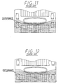
- Fig. 7 shows a plate fin 12 according to a second embodiment of the present invention.
- the tubes 10 are disposed in two parallel lines. However, in the second embodiment, the tubes 10 are disposed in one straight line perpendicular to the air flowing direction W, and the clearance holding portions 28 are disposed at an upstream side and a downstream side of the tubes 10 in the air flowing direction W.
- the other structures are similar to those of the first embodiment.
- the inventors experimentally produced conventional type plate fins shown in FIGS. 8 and 9 and a plate fin without the clearance holding portion shown in FIG. 10, and performed visualization experiments of air flow when each of the plate fins shown in FIGS. 8 through 10 and the plate fin of the second embodiment is employed.
- the experimental results are shown in FIGS. 11 through 14, respectively.
- the air flow is disturbed and meanders greatly at a downstream side of the clearance holding portions 28 as compared with the air flow shown in FIG. 13 in the plate fin without the clearance holding portion 28, so that the effect of the louvers 26 deteriorates.
- FIG. 8 and 9 the air flow is disturbed and meanders greatly at a downstream side of the clearance holding portions 28 as compared with the air flow shown in FIG. 13 in the plate fin without the clearance holding portion 28, so that the effect of the louvers 26 deteriorates.
- the air flow disturbance caused by the clearance holding portions 28 gives no adverse influence on the louvers 26, and air flowing through the louvers 26 does not meander, so that an effect similar to that of the plate fin without the clearance holding portion 28 can be obtained.
- the flow of air passing through the louvers 26 is made uniform, and the effect of the louvers 26 can be maintained sufficiently.
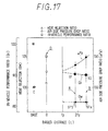
- FIGS. 15 through 17 (A) shows the plate fin shown in FIG. 8, (B) shows the plate fin in FIG. 9, (C) shows the plate fin in FIG. 10, and (D) shows the plate fin of the second embodiment of the present invention.
- FIG. 15 shows the pressure drop between the front side and rear side of the plate fin 12 in the air flowing direction W.
- the plate fin 12 of the second embodiment of the present invention has a lower pressure drop as compared with the conventional plate fins shown in FIGS. 8 and 9.
- the pressure drop is increased, the disturbance and the meander of the air flow are readily caused.
- each louvers 28 in the longitudinal direction of the plate fin 12 is indicated as fp
- a biased distance in the longitudinal direction of the plate fin 12 between a center of the clearance holding portion 28 and a center of tube 10 adjacent to the clearance holding portion is indicated as L, as shown in FIGS. 7 and 8.
- the biased distance L is zero.
- the plate fin without the clearance holding portion is standardized as a base, that is, the heat transfer coefficient ratio of the tube surface is set for 100% in the plate fin without the clearance holding portion 28.
- the heat transfer coefficient ratio of the surfaces of the tubes 10 of the plate fin 12 of the second embodiment are larger than the conventional plate fins 100 shown in FIGS. 8 and 9.
- the plate fin without the clearance holding portion is standardized as a base, and comparative experiments between the plate fin of the second embodiment and the conventional plate fins shown in FIGS. 8 and 9 are performed.
- an air side pressure drop ratio is decreased, a heat rejection ratio is increased, and an in-vehicle performance ratio is increased, as compared with the conventional plate fins shown in FIGS. 8 and 9.
Landscapes
- Engineering & Computer Science (AREA)
- Physics & Mathematics (AREA)
- Thermal Sciences (AREA)
- Mechanical Engineering (AREA)
- General Engineering & Computer Science (AREA)
- Geometry (AREA)
- Heat-Exchange Devices With Radiators And Conduit Assemblies (AREA)
- Air Filters, Heat-Exchange Apparatuses, And Housings Of Air-Conditioning Units (AREA)
Claims (8)
- Echangeur de chaleur à ailettes à plaques pour l'échange de chaleur entre un premier fluide et un second fluide, comprenant :caractérisé en ce que l'ouverture est disposée dans chaque ailette (12) de manière telle qu'une ligne passant à travers le centre de l'ouverture passe à travers le centre dudit tube (10) dans la direction d'écoulement (W).une pluralité d'ailettes à plaques (12) stratifiées l'une sur l'autre pour avoir un dégagement prédéterminé entre chaque paire d'ailettes à plaques adjacentes (12), ledit premier fluide passant à travers ledit dégagement ;une paire de parties de maintien (28) formée entre chaque paire d'ailettes à plaques adjacentes (12), pour maintenir ledit dégagement ;une pluralité de tubes (10) dans lesquels ledit second fluide s'écoule, lesdits tubes pénétrant à travers lesdites ailettes à plaques (12) dans une direction de stratification desdites ailettes à plaques (12) et étant agencés en série pour être perpendiculaires à une direction d'écoulement (W) dudit premier fluide ; dans lequelune pluralité de volets d'aération (26) est formée dans chacune desdites ailettes à plaques (12) entre chaque paire de tubes adjacents (10) pénétrant dans ladite ailette à plaques (12), lesdits volets d'aération (26) étant découpés et dépassant d'un côté de bord amont vers un côté de bord aval de ladite ailette à plaques (12) pour être en regard de l'écoulement dudit premier fluide,les deux parties desdites parties de maintien (28) sont espacées depuis un bord latéral de ladite pluralité de volets d'aération sur une distance prédéterminée (L) dans une direction perpendiculaire à la direction d'écoulement (W) dudit premier fluide,chaque ailette étant pourvue d'une ouverture,les deux parties de maintien (28) de chaque paire de parties de maintien étant disposées au niveau de la périphérie de l'ouverture disposée dans chaque ailette (12) ;les deux parties de maintien (28) de chaque paire de parties de maintien s'étendant parallèles à la direction d'écoulement (W) et étant disposées opposées l'une à l'autre ;
- Echangeur de chaleur du type à ailettes à plaques selon la revendication 1, dans lequel lesdites parties de maintien (28) sont formées au niveau d'un côté amont dudit tube (10).
- Echangeur de chaleur du type à ailettes à plaques selon la revendication 1, dans lequel lesdites parties de maintien (28) sont formées au niveau d'un côté aval dudit tube (10).
- Echangeur de chaleur du type à ailettes à plaques selon la revendication 1, dans lequel lesdits tubes (10) sont disposés en deux lignes parallèles perpendiculaires à ladite direction d'écoulement dudit premier fluide.
- Echangeur de chaleur du type à ailettes à plaques selon la revendication 1, dans lequel lesdites ailettes à plaques (12) et lesdits tubes (10) sont constitués d'un alliage d'aluminium.
- Echangeur de chaleur du type à ailettes à plaques selon la revendication 5, dans lequel lesdits tubes (10) et ailettes à plaques (12) sont raccordés les uns aux autres en dilatant lesdits tubes (10) après que lesdits tubes (10) sont insérés dans des trous (12a) formés dans lesdites ailettes à plaques (12).
- Echangeur de chaleur du type à ailettes à plaques selon la revendication 1, dans lequel :les parties de maintien (28) sont disposées au niveau d'un côté amont des volets d'aération (26) dans la direction d'écoulement (W) du premier fluide ; etune dimension de largeur entre les parties de maintien (28) est plus petite qu'une dimension de largeur de chaque volet d'aération (26) dans la direction perpendiculaire à la direction d'écoulement (W) du premier fluide.
- Echangeur de chaleur du type à ailettes à plaques selon la revendication 1, dans lequel chaque paire des parties de maintien est fournie en découpant et en maintenant une partie de chaque ailette à plaques.
Applications Claiming Priority (6)
| Application Number | Priority Date | Filing Date | Title |
|---|---|---|---|
| JP10522896 | 1996-04-25 | ||
| JP10522896 | 1996-04-25 | ||
| JP105228/96 | 1996-04-25 | ||
| JP84154/97 | 1997-04-02 | ||
| JP9084154A JPH109787A (ja) | 1996-04-25 | 1997-04-02 | プレートフィン型熱交換器 |
| JP8415497 | 1997-04-02 |
Publications (3)
| Publication Number | Publication Date |
|---|---|
| EP0803695A2 EP0803695A2 (fr) | 1997-10-29 |
| EP0803695A3 EP0803695A3 (fr) | 1998-08-26 |
| EP0803695B1 true EP0803695B1 (fr) | 2003-06-18 |
Family
ID=26425220
Family Applications (1)
| Application Number | Title | Priority Date | Filing Date |
|---|---|---|---|
| EP97106901A Expired - Lifetime EP0803695B1 (fr) | 1996-04-25 | 1997-04-25 | Echangeur de chaleur avec ailettes à plaques |
Country Status (5)
| Country | Link |
|---|---|
| EP (1) | EP0803695B1 (fr) |
| JP (1) | JPH109787A (fr) |
| KR (1) | KR100242760B1 (fr) |
| DE (1) | DE69722847T2 (fr) |
| ES (1) | ES2196210T3 (fr) |
Families Citing this family (7)
| Publication number | Priority date | Publication date | Assignee | Title |
|---|---|---|---|---|
| JP4096226B2 (ja) * | 2002-03-07 | 2008-06-04 | 三菱電機株式会社 | フィンチューブ型熱交換器、その製造方法及び冷凍空調装置 |
| KR101414179B1 (ko) * | 2008-04-24 | 2014-07-01 | 한라비스테온공조 주식회사 | 자동차용 열교환기 |
| FR2937719B1 (fr) * | 2008-10-29 | 2013-12-27 | Valeo Systemes Thermiques | Ailette pour echangeur de chaleur et echangeur de chaleur comportant une telle ailette |
| US20120199310A1 (en) * | 2009-07-07 | 2012-08-09 | A-Heat Allied Heat Exchange Technology Ag | Heat exchange system, as well as a method for the operation of a heat exchange system |
| JP5177307B2 (ja) * | 2011-01-21 | 2013-04-03 | ダイキン工業株式会社 | 熱交換器 |
| JP2015132468A (ja) * | 2015-04-22 | 2015-07-23 | 三菱電機株式会社 | 空気調和機の熱交換器 |
| JP2017083041A (ja) * | 2015-10-26 | 2017-05-18 | 株式会社富士通ゼネラル | 熱交換器 |
Family Cites Families (13)
| Publication number | Priority date | Publication date | Assignee | Title |
|---|---|---|---|---|
| GB1313974A (en) * | 1971-05-11 | 1973-04-18 | Hutogepgyar | Tubular heat exchanger and a method for the production thereof |
| JPS4858434A (fr) * | 1971-11-22 | 1973-08-16 | ||
| JPS55107896A (en) * | 1979-02-08 | 1980-08-19 | Nippon Denso Co Ltd | Heat exchanger |
| JPS58127092A (ja) * | 1982-01-25 | 1983-07-28 | Nippon Denso Co Ltd | 熱交換器及びその製法 |
| EP0086559A3 (fr) * | 1982-02-16 | 1984-01-11 | Unipart Group Limited | Echangeurs de chaleur |
| JPS6060590U (ja) * | 1983-09-28 | 1985-04-26 | カルソニックカンセイ株式会社 | 熱交換器 |
| JPS61107097A (ja) * | 1984-10-31 | 1986-05-24 | Matsushita Electric Ind Co Ltd | 熱交換器 |
| JPH0161572U (fr) * | 1987-10-05 | 1989-04-19 | ||
| JPH01178481U (fr) * | 1988-06-07 | 1989-12-20 | ||
| JPH0363499A (ja) * | 1989-07-31 | 1991-03-19 | Matsushita Refrig Co Ltd | フィン付熱交換器 |
| JP2572658Y2 (ja) * | 1992-06-17 | 1998-05-25 | 株式会社ニチリン | 自動車用オイルクーラ |
| JP3264525B2 (ja) * | 1992-10-12 | 2002-03-11 | 東芝キヤリア株式会社 | 熱交換器 |
| DE4404837A1 (de) * | 1994-02-16 | 1995-08-17 | Behr Gmbh & Co | Rippe für Wärmetauscher |
-
1997
- 1997-04-02 JP JP9084154A patent/JPH109787A/ja active Pending
- 1997-04-24 KR KR1019970015456A patent/KR100242760B1/ko not_active IP Right Cessation
- 1997-04-25 EP EP97106901A patent/EP0803695B1/fr not_active Expired - Lifetime
- 1997-04-25 ES ES97106901T patent/ES2196210T3/es not_active Expired - Lifetime
- 1997-04-25 DE DE69722847T patent/DE69722847T2/de not_active Expired - Fee Related
Also Published As
| Publication number | Publication date |
|---|---|
| KR19980078062A (ko) | 1998-11-16 |
| EP0803695A2 (fr) | 1997-10-29 |
| DE69722847D1 (de) | 2003-07-24 |
| DE69722847T2 (de) | 2004-05-13 |
| EP0803695A3 (fr) | 1998-08-26 |
| JPH109787A (ja) | 1998-01-16 |
| ES2196210T3 (es) | 2003-12-16 |
| KR100242760B1 (ko) | 2000-03-02 |
Similar Documents
| Publication | Publication Date | Title |
|---|---|---|
| EP0021651B1 (fr) | Aillettes en forme de jalousie pour échangeurs de chaleur | |
| US6213196B1 (en) | Double heat exchanger for vehicle air conditioner | |
| US4945981A (en) | Oil cooler | |
| EP1231448B1 (fr) | Echangeur de chaleur | |
| AU2002343716B2 (en) | Split fin for a heat exchanger | |
| US4958681A (en) | Heat exchanger with bypass channel louvered fins | |
| US3993125A (en) | Heat exchange device | |
| JP2555449B2 (ja) | 熱交換器 | |
| US6209628B1 (en) | Heat exchanger having several heat exchanging portions | |
| US20050061488A1 (en) | Automotive heat exchanger | |
| US8167028B2 (en) | Heat exchanger fin with planar crests and troughs having slits | |
| JPH11287580A (ja) | 熱交換器 | |
| US20030075307A1 (en) | Exchanger of thermal energy with multiple cores and a thermal barrier | |
| US5975200A (en) | Plate-fin type heat exchanger | |
| US5738168A (en) | Fin tube heat exchanger | |
| US5634270A (en) | Method for making off-set louvered heat exchanger fin | |
| EP1195566B1 (fr) | Echangeur de chaleur comportant plusieurs portions d'échange de chaleur | |
| US6871399B2 (en) | Method for producing an integrated heat exchanger and an integrated heat exchanger produced thereby | |
| US5062474A (en) | Oil cooler | |
| US6942024B2 (en) | Corrugated heat exchange element | |
| EP0803695B1 (fr) | Echangeur de chaleur avec ailettes à plaques | |
| JP2568968Y2 (ja) | 熱交換器 | |
| JPH0755380A (ja) | 熱交換器 | |
| KR20030047051A (ko) | 열교환기용 핀과 그것을 구비한 열교환기 및, 열교환기조립체 | |
| JP3861787B2 (ja) | 複合熱交換器及びこれを備える自動車 |
Legal Events
| Date | Code | Title | Description |
|---|---|---|---|
| PUAI | Public reference made under article 153(3) epc to a published international application that has entered the european phase |
Free format text: ORIGINAL CODE: 0009012 |
|
| AK | Designated contracting states |
Kind code of ref document: A2 Designated state(s): DE ES FR GB IT |
|
| PUAL | Search report despatched |
Free format text: ORIGINAL CODE: 0009013 |
|
| AK | Designated contracting states |
Kind code of ref document: A3 Designated state(s): DE ES FR GB IT |
|
| 17P | Request for examination filed |
Effective date: 19980930 |
|
| 17Q | First examination report despatched |
Effective date: 20000818 |
|
| GRAH | Despatch of communication of intention to grant a patent |
Free format text: ORIGINAL CODE: EPIDOS IGRA |
|
| RTI1 | Title (correction) |
Free format text: PLATE-FIN HEAT EXCHANGER |
|
| GRAH | Despatch of communication of intention to grant a patent |
Free format text: ORIGINAL CODE: EPIDOS IGRA |
|
| GRAA | (expected) grant |
Free format text: ORIGINAL CODE: 0009210 |
|
| AK | Designated contracting states |
Designated state(s): DE ES FR GB IT |
|
| REG | Reference to a national code |
Ref country code: GB Ref legal event code: FG4D |
|
| REF | Corresponds to: |
Ref document number: 69722847 Country of ref document: DE Date of ref document: 20030724 Kind code of ref document: P |
|
| REG | Reference to a national code |
Ref country code: ES Ref legal event code: FG2A Ref document number: 2196210 Country of ref document: ES Kind code of ref document: T3 |
|
| ET | Fr: translation filed | ||
| PGFP | Annual fee paid to national office [announced via postgrant information from national office to epo] |
Ref country code: FR Payment date: 20040408 Year of fee payment: 8 |
|
| PGFP | Annual fee paid to national office [announced via postgrant information from national office to epo] |
Ref country code: ES Payment date: 20040416 Year of fee payment: 8 |
|
| PGFP | Annual fee paid to national office [announced via postgrant information from national office to epo] |
Ref country code: GB Payment date: 20040421 Year of fee payment: 8 |
|
| PLBE | No opposition filed within time limit |
Free format text: ORIGINAL CODE: 0009261 |
|
| STAA | Information on the status of an ep patent application or granted ep patent |
Free format text: STATUS: NO OPPOSITION FILED WITHIN TIME LIMIT |
|
| PGFP | Annual fee paid to national office [announced via postgrant information from national office to epo] |
Ref country code: DE Payment date: 20040506 Year of fee payment: 8 |
|
| 26N | No opposition filed |
Effective date: 20040319 |
|
| PG25 | Lapsed in a contracting state [announced via postgrant information from national office to epo] |
Ref country code: IT Free format text: LAPSE BECAUSE OF NON-PAYMENT OF DUE FEES;WARNING: LAPSES OF ITALIAN PATENTS WITH EFFECTIVE DATE BEFORE 2007 MAY HAVE OCCURRED AT ANY TIME BEFORE 2007. THE CORRECT EFFECTIVE DATE MAY BE DIFFERENT FROM THE ONE RECORDED. Effective date: 20050425 Ref country code: GB Free format text: LAPSE BECAUSE OF NON-PAYMENT OF DUE FEES Effective date: 20050425 |
|
| PG25 | Lapsed in a contracting state [announced via postgrant information from national office to epo] |
Ref country code: ES Free format text: LAPSE BECAUSE OF NON-PAYMENT OF DUE FEES Effective date: 20050426 |
|
| PG25 | Lapsed in a contracting state [announced via postgrant information from national office to epo] |
Ref country code: DE Free format text: LAPSE BECAUSE OF NON-PAYMENT OF DUE FEES Effective date: 20051101 |
|
| GBPC | Gb: european patent ceased through non-payment of renewal fee |
Effective date: 20050425 |
|
| PG25 | Lapsed in a contracting state [announced via postgrant information from national office to epo] |
Ref country code: FR Free format text: LAPSE BECAUSE OF NON-PAYMENT OF DUE FEES Effective date: 20051230 |
|
| REG | Reference to a national code |
Ref country code: FR Ref legal event code: ST Effective date: 20051230 |
|
| REG | Reference to a national code |
Ref country code: ES Ref legal event code: FD2A Effective date: 20050426 |