EP0803385A2 - Dispositif de suspension - Google Patents
Dispositif de suspension Download PDFInfo
- Publication number
- EP0803385A2 EP0803385A2 EP97106842A EP97106842A EP0803385A2 EP 0803385 A2 EP0803385 A2 EP 0803385A2 EP 97106842 A EP97106842 A EP 97106842A EP 97106842 A EP97106842 A EP 97106842A EP 0803385 A2 EP0803385 A2 EP 0803385A2
- Authority
- EP
- European Patent Office
- Prior art keywords
- wheel
- vehicle height
- wheels
- actuators
- working fluid
- Prior art date
- Legal status (The legal status is an assumption and is not a legal conclusion. Google has not performed a legal analysis and makes no representation as to the accuracy of the status listed.)
- Granted
Links
Images

Classifications
-
- B—PERFORMING OPERATIONS; TRANSPORTING
- B60—VEHICLES IN GENERAL
- B60G—VEHICLE SUSPENSION ARRANGEMENTS
- B60G17/00—Resilient suspensions having means for adjusting the spring or vibration-damper characteristics, for regulating the distance between a supporting surface and a sprung part of vehicle or for locking suspension during use to meet varying vehicular or surface conditions, e.g. due to speed or load
- B60G17/02—Spring characteristics, e.g. mechanical springs and mechanical adjusting means
- B60G17/04—Spring characteristics, e.g. mechanical springs and mechanical adjusting means fluid spring characteristics
- B60G17/0416—Spring characteristics, e.g. mechanical springs and mechanical adjusting means fluid spring characteristics regulated by varying the resiliency of hydropneumatic suspensions
-
- B—PERFORMING OPERATIONS; TRANSPORTING
- B60—VEHICLES IN GENERAL
- B60G—VEHICLE SUSPENSION ARRANGEMENTS
- B60G17/00—Resilient suspensions having means for adjusting the spring or vibration-damper characteristics, for regulating the distance between a supporting surface and a sprung part of vehicle or for locking suspension during use to meet varying vehicular or surface conditions, e.g. due to speed or load
- B60G17/015—Resilient suspensions having means for adjusting the spring or vibration-damper characteristics, for regulating the distance between a supporting surface and a sprung part of vehicle or for locking suspension during use to meet varying vehicular or surface conditions, e.g. due to speed or load the regulating means comprising electric or electronic elements
- B60G17/016—Resilient suspensions having means for adjusting the spring or vibration-damper characteristics, for regulating the distance between a supporting surface and a sprung part of vehicle or for locking suspension during use to meet varying vehicular or surface conditions, e.g. due to speed or load the regulating means comprising electric or electronic elements characterised by their responsiveness, when the vehicle is travelling, to specific motion, a specific condition, or driver input
-
- B—PERFORMING OPERATIONS; TRANSPORTING
- B60—VEHICLES IN GENERAL
- B60G—VEHICLE SUSPENSION ARRANGEMENTS
- B60G2202/00—Indexing codes relating to the type of spring, damper or actuator
- B60G2202/30—Spring/Damper and/or actuator Units
- B60G2202/31—Spring/Damper and/or actuator Units with the spring arranged around the damper, e.g. MacPherson strut
- B60G2202/312—The spring being a wound spring
-
- B—PERFORMING OPERATIONS; TRANSPORTING
- B60—VEHICLES IN GENERAL
- B60G—VEHICLE SUSPENSION ARRANGEMENTS
- B60G2202/00—Indexing codes relating to the type of spring, damper or actuator
- B60G2202/40—Type of actuator
- B60G2202/41—Fluid actuator
- B60G2202/413—Hydraulic actuator
-
- B—PERFORMING OPERATIONS; TRANSPORTING
- B60—VEHICLES IN GENERAL
- B60G—VEHICLE SUSPENSION ARRANGEMENTS
- B60G2400/00—Indexing codes relating to detected, measured or calculated conditions or factors
- B60G2400/10—Acceleration; Deceleration
- B60G2400/102—Acceleration; Deceleration vertical
-
- B—PERFORMING OPERATIONS; TRANSPORTING
- B60—VEHICLES IN GENERAL
- B60G—VEHICLE SUSPENSION ARRANGEMENTS
- B60G2400/00—Indexing codes relating to detected, measured or calculated conditions or factors
- B60G2400/20—Speed
- B60G2400/204—Vehicle speed
-
- B—PERFORMING OPERATIONS; TRANSPORTING
- B60—VEHICLES IN GENERAL
- B60G—VEHICLE SUSPENSION ARRANGEMENTS
- B60G2400/00—Indexing codes relating to detected, measured or calculated conditions or factors
- B60G2400/25—Stroke; Height; Displacement
- B60G2400/252—Stroke; Height; Displacement vertical
-
- B—PERFORMING OPERATIONS; TRANSPORTING
- B60—VEHICLES IN GENERAL
- B60G—VEHICLE SUSPENSION ARRANGEMENTS
- B60G2400/00—Indexing codes relating to detected, measured or calculated conditions or factors
- B60G2400/30—Propulsion unit conditions
-
- B—PERFORMING OPERATIONS; TRANSPORTING
- B60—VEHICLES IN GENERAL
- B60G—VEHICLE SUSPENSION ARRANGEMENTS
- B60G2400/00—Indexing codes relating to detected, measured or calculated conditions or factors
- B60G2400/30—Propulsion unit conditions
- B60G2400/39—Brake pedal position
-
- B—PERFORMING OPERATIONS; TRANSPORTING
- B60—VEHICLES IN GENERAL
- B60G—VEHICLE SUSPENSION ARRANGEMENTS
- B60G2400/00—Indexing codes relating to detected, measured or calculated conditions or factors
- B60G2400/40—Steering conditions
- B60G2400/41—Steering angle
-
- B—PERFORMING OPERATIONS; TRANSPORTING
- B60—VEHICLES IN GENERAL
- B60G—VEHICLE SUSPENSION ARRANGEMENTS
- B60G2500/00—Indexing codes relating to the regulated action or device
- B60G2500/30—Height or ground clearance
-
- B—PERFORMING OPERATIONS; TRANSPORTING
- B60—VEHICLES IN GENERAL
- B60G—VEHICLE SUSPENSION ARRANGEMENTS
- B60G2600/00—Indexing codes relating to particular elements, systems or processes used on suspension systems or suspension control systems
- B60G2600/18—Automatic control means
- B60G2600/182—Active control means
-
- B—PERFORMING OPERATIONS; TRANSPORTING
- B60—VEHICLES IN GENERAL
- B60G—VEHICLE SUSPENSION ARRANGEMENTS
- B60G2600/00—Indexing codes relating to particular elements, systems or processes used on suspension systems or suspension control systems
- B60G2600/20—Manual control or setting means
-
- B—PERFORMING OPERATIONS; TRANSPORTING
- B60—VEHICLES IN GENERAL
- B60G—VEHICLE SUSPENSION ARRANGEMENTS
- B60G2800/00—Indexing codes relating to the type of movement or to the condition of the vehicle and to the end result to be achieved by the control action
- B60G2800/90—System Controller type
- B60G2800/91—Suspension Control
- B60G2800/914—Height Control System
Definitions
- the present invention relates to a suspension apparatus for controlling feed and discharge of a working fluid to and from actuators interposed between a vehicle body and respective wheels, so as to adjust the vehicle height.
- suspension apparatuses which feed and discharge a working fluid to and from actuators in order to adjust the vehicle height, have functions discussed below.
- the suspension apparatus lowers the vehicle height from a standard level in an ordinary-speed driving condition, in order to ensure the driving stability.
- the suspension apparatus works to keep the vehicle height at a fixed level, irrespective of a variation in number of passengers or weight of loading.
- the suspension apparatus can also lower the vehicle height from a standard level in a driving condition, in order to enable a driver and other passengers to easily ride on or get off the vehicle.
- the suspension apparatus may be provided with a switch that is used to change the vehicle height between a high level and a low level arbitrarily.
- the vehicle height can be lowered or raised according to the requirement specified through an operation of the switch.
- a control valve is driven and regulated to make the vehicle height at the moment (hereinafter referred to as the current vehicle height) coincide with a target vehicle height.
- a proposed technique enables the vehicle height to be adjusted separately at the front wheels and at the rear wheels and assures a forward-leaning attitude, wherein the vehicle height at the front wheels is lower than that at the rear wheels, while the vehicle runs (JAPANESE PATENT LAYING-OPEN GAZETTE No. 2-237811).
- Such a forward-leading attitude improves the aerodynamic properties of the vehicle and ensures the stability under the high-speed driving condition.
- the vehicle height at the front wheels may temporarily become higher than the vehicle height at the rear wheels.
- the head lamps arranged on the side of the front wheels having the higher vehicle height turn upward and may blind the driver in a vehicle running in the opposite direction.
- Another proposed technique carries out a decrease in vehicle height at the front wheels prior to a decrease in vehicle height at the rear wheels and alternately implements the decrease in vehicle height at the front wheels and at the rear wheels in a stepwise manner.
- the procedure of alternately lowering the vehicle height at the front wheels and at the rear wheels effectively prevents the head lamps from turning upward and blinding the driver in a vehicle running in the opposite direction.
- This proposed technique has the following drawback. In this structure, while a decrease in vehicle height is carried out on one side (for example, at the front wheels), a decrease in vehicle height is in wait on the other side (for example, at the rear wheels). Such a waiting state is repeated alternately at the front wheels and at the rear wheels. This makes the required time period for completing the decrease in vehicle height undesirably long.
- the object of the present invention is to prevent the head lamps from turning upward and blinding the driver in a vehicle running in the opposite direction in the course of lowering the vehicle height and, at the same time, shorten the required time period for completing the decrease in vehicle height.
- a first suspension apparatus for a vehicle which includes: actuators for respective wheels interposed between a vehicle body and the respective wheels for suspending the vehicle body and changing a vehicle height through supply and discharge of a working fluid; and control means for controlling the supply and discharge of the working fluid to and from the actuators for the respective wheels, thereby adjusting the vehicle height, the control means enabling the working fluid to be discharged from the actuators for left and right front wheels so as to lower a front-wheel vehicle height at the left and right front wheels at a first descending rate, while enabling the working fluid to be discharged from the actuators for left and right rear wheels so as to lower a rear-wheel vehicle height at the left and right rear wheels at a second descending rate that is less than the first descending rate.
- the first descending rate, at which the working fluid is discharged from the actuators for the left and right front wheels so as to lower the front-wheel vehicle height is greater than the second descending rate, at which the working fluid is discharged from the actuators for the left and right rear wheels so as to lower the rear-wheel vehicle height.
- the vehicle height at the front wheels is lowered faster than the vehicle height at the rear wheels.
- the structure of the first suspension apparatus prevents the vehicle height at the front wheels from being higher than the vehicle height at the rear wheels and thereby prevents the head lamps from turning upward and blinding the driver in a vehicle running in the opposite direction in the course of lowering the vehicle height.
- the greater rate of lowering the vehicle height at the front wheels shortens the waiting time at the rear wheels, thereby desirably shortening the required time period for completing the decrease in vehicle height.
- the first suspension apparatus further includes: a first conduit which the working fluid discharged from the actuators for the left and right front wheels passes through; and a second conduit which the working fluid discharged from the actuators for the left and right rear wheels passes through, wherein the first conduit has a smaller flow resistance than that of the second conduit, so as to make the first descending rate at the left and right front wheels greater than the second descending rate at the left and right rear wheels.
- the first conduit which the working fluid discharged from the actuators for the left and right front wheels (hereinafter may be referred to as the front-wheel actuators) passes through, has a smaller flow resistance than that of the second conduit, which the working fluid discharged from the actuators for the left and right rear wheels (hereinafter may be referred to as the rear-wheel actuators) passes through.
- the front-wheel actuators the working fluid discharged from the actuators for the left and right rear wheels
- the first suspension apparatus of this preferable structure thus effectively prevents the head lamps from turning upward and blinding the driver in a vehicle running in the opposite direction in the course of lowering the vehicle height.
- the greater rate of lowering the vehicle height at the front wheels shortens the required time period for completing the decrease in vehicle height.
- the present invention is also directed to a second suspension apparatus, which includes actuators for respective wheels interposed between a vehicle body and the respective wheels for suspending the vehicle body and changing a vehicle height through supply and discharge of a working fluid, and controls the supply and discharge of the working fluid to and from the actuators for the respective wheels, thereby adjusting the vehicle height.
- the second suspension apparatus further includes: front-wheel control means for controlling supply and discharge of the working fluid to and from the actuators for left and right front wheels; and rear-wheel control means for controlling supply and discharge of the working fluid to and from the actuators for left and right rear wheels.
- the front-wheel control means is provided with front-wheel working-fluid discharge means for causing the working fluid to be discharged from the actuators for the left and right front wheels and thereby lowering a front-wheel vehicle height at the left and right front wheels at a first descending rate.
- the rear-wheel control means has rear-wheel working-fluid discharge means for causing the working fluid to be discharged from the actuators for the left and right rear wheels and thereby lowering a rear-wheel vehicle height at the left and right rear wheels at a second descending rate that is less than the first descending rate.
- the first descending rate, at which the working fluid is discharged from the actuators for the left and right front wheels so as to lower the front-wheel vehicle height is greater than the second descending rate, at which the working fluid is discharged from the actuators for the left and right rear wheels so as to lower the rear-wheel vehicle height.
- the vehicle height at the front wheels is lowered faster than the vehicle height at the rear wheels.
- the structure of the second suspension apparatus also prevents the vehicle height at the front wheels from being higher than the vehicle height at the rear wheels and thereby prevents the head lamps from turning upward and blinding the driver in a vehicle running in the opposite direction in the course of lowering the vehicle height.
- the greater rate of lowering the vehicle height at the front wheels shortens the waiting time at the rear wheels, thereby desirably shortening the required time period for completing the decrease in vehicle height.
- the front-wheel working-fluid discharge means causes the working fluid to be discharged from the actuators for the left and right front wheels and pass through a front-wheel conduit having a first flow resistance, thereby lowering the front-wheel vehicle height at the first descending rate.
- the rear-wheel working-fluid discharge means causes the working fluid to be discharged from the actuators for the left and right rear wheels and pass through a rear-wheel conduit having a second flow resistance, which is greater than the first flow resistance of the front-wheel conduit, thereby lowering the rear-wheel vehicle height at the second descending rate.
- the rear-wheel conduit has a greater flow resistance than that of the front-wheel conduit.
- the working fluid is accordingly discharged from the front-wheel actuators at a greater rate than that from the rear-wheel actuators, so that the vehicle height at the front wheels is lowered faster than the vehicle height at the rear wheels.
- the second suspension apparatus of this preferable structure thus effectively prevents the head lamps from turning upward and blinding the driver in a vehicle running in the opposite direction in the course of lowering the vehicle height.
- the greater rate of lowering the vehicle height at the front wheels shortens the required time period for completing the decrease in vehicle height.
- the rear-wheel control means starts control of a discharge of the working fluid from the corresponding actuators to lower the vehicle height, substantially simultaneously with control of a discharge of the working fluid from the corresponding actuators by the front-wheel control means.
- the discharge of the working fluid from the front-wheel actuators is carried out substantially simultaneously with the discharge of the working fluid from the rear-wheel actuators.
- the decrease in vehicle height at the front wheels is carried out substantially concurrently with the decrease in vehicle height at the rear wheels, the greater rate of lowering the vehicle height at the front wheels than that at the rear wheels prevents the vehicle height at the front wheels from being higher than the vehicle height at the rear wheels.
- the second suspension apparatus of this structure thus effectively prevents the head lamps from turning upward and blinding the driver in a vehicle running in the opposite direction in the course of lowering the vehicle height.
- the simultaneous decrease in vehicle height at the front wheels and at the rear wheels does not require any waiting time, during which a decrease in vehicle height is in wait either at the front wheels or at the rear wheels.
- This structure further shortens the required time period for completing the decrease in vehicle height.
- the second suspension apparatus of the present invention or that of the first application further includes: vehicle height comparing means for comparing the front-wheel vehicle height at the left and right front wheels with the rear-wheel vehicle height at the left and right rear wheels, wherein the rear-wheel control means has delay means for, when the front-wheel vehicle height is higher than the rear-wheel vehicle height, delaying control of a discharge of the working fluid from the actuators to lower the vehicle height until the front-wheel vehicle height becomes lower than the rear-wheel vehicle height.
- the decrease in vehicle height at the front wheels is carried out substantially simultaneously with the decrease in vehicle height at the rear wheels, with a view to preventing the blinding and shortening the time period for the decrease in vehicle height.
- the substantially simultaneous discharge of the working fluid at the front wheels and at the rear wheels is stopped and the discharge of the working fluid from the rear-wheel actuators is delayed.
- the discharge of the working fluid from the front-wheel actuators is carried out prior to the discharge of the working fluid from the rear-wheel actuators, so that the decrease in vehicle height at the front wheels is implemented prior to the decrease in vehicle height at the rear wheels.
- the discharge of the working fluid from the rear-wheel actuators is started to lower the vehicle height at the rear wheels.
- the second suspension apparatus of the third application does not carry out the decrease in vehicle height, while the front-wheel vehicle height is higher than the rear-wheel vehicle height. This structure securely prevents the blinding and quickly completes the decrease in vehicle height.
- the second suspension apparatus of the present invention or that of the first application further includes: vehicle height comparing means for comparing the front-wheel vehicle height at the left and right front wheels with the rear-wheel vehicle height at the left and right rear wheels, wherein the rear-wheel control means has interruption means for, when the rear-wheel vehicle height that is higher than the front-wheel vehicle height becomes closer to the front-wheel vehicle height to have a difference of not greater than a predetermined value, temporarily stopping control of a discharge of the working fluid from the actuators to lower the vehicle height.
- the decrease in vehicle height at the front wheels is carried out substantially simultaneously with the decrease in vehicle height at the rear wheels, with a view to preventing the blinding and shortening the time period for completing the decrease in vehicle height.
- the substantially simultaneous discharge of the working fluid at the front wheels and at the rear wheels is stopped and the discharge of the working fluid from the rear-wheel actuators is temporarily interrupted.
- the discharge of the working fluid from the front-wheel actuators is continued while the same from the rear-wheel actuators is temporarily interrupted.
- the possible reason why the rear-wheel vehicle height that is higher than the front-wheel vehicle height becomes closer to the front-wheel vehicle height to have a difference of not greater than a predetermined value is an increase in loading at the rear wheels due to a shift of passengers or an increase in number of passengers.
- the present invention is further directed to a third suspension apparatus, which includes actuators for respective wheels interposed between a vehicle body and the respective wheels for suspending the vehicle body and changing a vehicle height through supply and discharge of a working fluid, and controls the supply and discharge of the working fluid to and from the actuators for the respective wheels, thereby adjusting the vehicle height.
- the third suspension apparatus further includes: front-wheel control means for controlling supply and discharge of the working fluid to and from the actuators for left and right front wheels; and rear-wheel control means for controlling supply and discharge of the working fluid to and from the actuators for left and right rear wheels.
- the front-wheel control means is provided with front-wheel discharge means for continuing discharge of the working fluid from the actuators for the left and right front wheels to lower the vehicle height.
- the rear-wheel control means is provided with rear-wheel discharge means for starting and then continuing discharge of the working fluid from the actuators for the left and right rear wheels to lower the vehicle height, while the front-wheel discharge means continues the discharge of the working fluid from the actuators for the left and right front wheels.
- the discharge of the working fluid from the front-wheel actuators continues to continuously lower the front-wheel vehicle height.
- the discharge of the working fluid from the rear-wheel actuators starts and continues while the discharge of the working fluid from the front-wheel actuators continues. Namely the rear-wheel vehicle height starts lowering while the front-wheel vehicle height is being lowered.
- This structure enables the decrease in front-wheel vehicle height prior to the decrease in rear-wheel vehicle height, and subsequently carries out the simultaneous decrease in vehicle height both at the front wheels and at the rear wheels.
- the structure of the third suspension apparatus also prevents the vehicle height at the front wheels from being higher than the vehicle height at the rear wheels and thereby prevents the head lamps from turning upward and blinding the driver in a vehicle running in the opposite direction in the course of lowering the vehicle height.
- the simultaneous decrease in vehicle height at the front wheels and at the rear wheels after the start of lowering the vehicle height at the rear wheels effectively shortens the required time period for completing the decrease in vehicle height.
- a front-wheel conduit which the front-wheel discharge means enables the working fluid discharged from the actuators for the left and right front wheels to pass through, has a first flow resistance
- a rear-wheel conduit which the rear-wheel discharge means enables the working fluid discharged from the actuators for the left and right rear wheels to pass through, has a second flow resistance that is greater than the first flow resistance
- the front-wheel conduit, which the working fluid discharged from the front-wheel actuators passes through has a smaller flow resistance than that of the rear-wheel conduit, which the working fluid discharged from the rear-wheel actuators passes through.
- the flow rate of the working fluid through the front-wheel conduit is accordingly higher than the flow rate of the working fluid through the rear-wheel conduit.
- the third suspension apparatus of this structure thus prevents the head lamps from turning upward and blinding the driver in a vehicle running in the opposite direction in the course of lowering the vehicle height.
- the improvement in descending rate of the vehicle height at the front wheels and the simultaneous decrease in vehicle height at the front wheels and at the rear wheels shorten the required time period for completing the decrease in vehicle height.
- the third suspension apparatus further includes vehicle height comparing means for comparing the front-wheel vehicle height at the left and right front wheels with the rear-wheel vehicle height at the left and right rear wheels, wherein the rear-wheel control means has delay means for, when the front-wheel vehicle height is higher than the rear-wheel vehicle height, delaying a start of the discharge of the working fluid by the rear-wheel discharge means until the front-wheel vehicle height becomes lower than the rear-wheel vehicle height.
- the discharge of the working fluid from the rear-wheel actuators starts and continues while the discharge of the working fluid from the front-wheel actuators continues. This realizes the prevention of the blinding and the quick decrease in vehicle height.
- the start of discharging the working fluid from the rear-wheel actuators is delayed while the discharge of the working fluid from the front-wheel actuators continues.
- the third suspension apparatus further includes vehicle height comparing means for comparing the front-wheel vehicle height at the left and right front wheels with the rear-wheel vehicle height at the left and right rear wheels, wherein the rear-wheel control means has interruption means for, when the rear-wheel vehicle height that is higher than the front-wheel vehicle height becomes closer to the front-wheel vehicle height to have a difference of not greater than a predetermined value, temporarily stopping the discharge of the working fluid by the rear-wheel discharge means.
- the decrease in front-wheel vehicle height prior to the decrease in rear-wheel vehicle height and the subsequent simultaneous decrease in vehicle height at the front wheels and at the rear wheels realize the prevention of the blinding and the quick decrease in vehicle height.
- the simultaneous discharge of the working fluid at the front wheels and at the rear wheels is stopped and the discharge of the working fluid from the rear-wheel actuators is temporarily interrupted.
- the discharge of the working fluid from the front-wheel actuators is continued while the same from the rear-wheel actuators is temporarily interrupted.
- the present invention is also directed to a fourth suspension apparatus, which includes actuators for respective wheels interposed between a vehicle body and the respective wheels for suspending the vehicle body and changing a vehicle height through supply and discharge of a working fluid, and controls the supply and discharge of the working fluid to and from the actuators for the respective wheels, thereby adjusting the vehicle height.
- the fourth suspension apparatus further includes: a front-wheel control valve for controlling supply and discharge of the working fluid to and from the actuators for left and right front wheels; a rear-wheel control valve for controlling supply and discharge of the working fluid to and from the actuators for left and right rear wheels; a front-wheel connection control valve disposed in a flow path between the front-wheel control valve and the actuators for the left and right front wheels, the front-wheel connection control valve switching the actuators for the left and right front wheels between a connecting position and a disconnecting position; a rear-wheel connection control valve disposed in a flow path between the rear-wheel control valve and the actuators for the left and right rear wheels, the rear-wheel connection control valve switching the actuators for the left and right rear wheels between a connecting position and a disconnecting position; and by-pass means for by-passing the front-wheel connection control valve and leading the working fluid to the front-wheel control valve only when the working fluid is discharged from the actuators for the left and right front wheels.
- the fourth suspension apparatus of the present invention adjusts the vehicle height by carrying out the discharge and supply of the working fluid from and to the front-wheel actuators via the front-wheel control valve and the discharge and supply of the working fluid from and to the rear-wheel actuators via the rear-wheel control valve.
- the front-wheel connection control valve and the rear-wheel connection control valve arranged after the front-wheel control valve and the rear-wheel control valve respectively switch the front-wheel actuators and the rear-wheel actuators between a connecting position and a disconnecting position.
- An extreme input of road surface causes vibrations of the left and right wheels in reversed phases along the vertical axis, and the internal pressures of the actuators for the left and right wheels are significantly varied in an alternating manner. This leads to an excessive increase in pressure in the whole system including these actuators.
- the front-wheel actuators and the rear-wheel actuators in the connecting position enable a working fluid to be fed to the wheels on one side, in order to relieve an increase in internal pressure of the wheels on the other side, thereby depressing the increase in pressure.
- connection of the actuators ensures the sufficient grips of the left and right wheels independently, so as to improve the driving stability.
- connection of the actuators for the left and right wheels enables the internal pressures of the actuators to be substantially equal to each other after the shift to the flat road surface. This effectively prevents the attitude of the vehicle body from being unnaturally inclined.
- the front-wheel actuators and the rear-wheel actuators are in the connecting position at a turn of the vehicle, on the other hand, the rolling angle increases with an increase in steering angle. In this case, the front-wheel actuators and the rear-wheel actuators are switched to a disconnecting position, in order to depress the increase in rolling angle.
- the state of discharging the working fluid from the actuators to lower the vehicle height at the front wheels is different from that at the rear wheels.
- the by-pass means enables the working fluid to by-pass the front-wheel connection control valve and to be led to the front-wheel control valve.
- the working fluid is led to the rear-wheel control valve via the rear-wheel connection control valve.
- Each connection control valve for switching the corresponding actuators between the connecting position and the disconnecting position generally has an orifice arranged therein.
- the working fluid discharged from the actuators to lower the vehicle height passes through this orifice.
- the flow (discharge) of the working fluid is made by the internal pressure of the actuators generated by the dead weight of the vehicle body. The pressure loss due to the flow through the orifice decreases the flow rate of the working fluid.
- the working fluid discharged from the front-wheel actuators by-passes the front-wheel connection control valve as discussed previously.
- This structure effectively reduces the pressure loss, compared with the structure at the rear wheels, wherein the working fluid discharged from the rear-wheel actuators does not by-pass the rear-wheel connection control valve.
- the greater descending rate of the front-wheel vehicle height than the descending rate of the rear-wheel vehicle height enables the vehicle height at the front wheels to be lowered faster than the vehicle height at the rear wheels.
- the structure of the fourth suspension apparatus prevents the vehicle height at the front wheels from being higher than the vehicle height at the rear wheels and thereby prevents the head lamps from turning upward and blinding the driver in a vehicle running in the opposite direction in the course of lowering the vehicle height. Even when the decrease in vehicle height at the front wheels and the decrease in vehicle height at the rear wheels are carried out alternately in a stepwise manner, the greater rate of lowering the vehicle height at the front wheels shortens the waiting time at the rear wheels, thereby desirably shortening the required time period for completing the decrease in vehicle height.
- Part of the objects of the present invention is also realized by a method of controlling a suspension apparatus, which includes actuators interposed between a vehicle body and respective wheels for suspending the vehicle body and changing a vehicle height through supply and discharge of a working fluid and thereby adjusts the vehicle height.
- the method of the present invention includes the steps of:
- the descending rate of the front-wheel vehicle height is greater than the descending rate of the rear-wheel vehicle height. Namely the vehicle height at the front wheels is lowered faster than the vehicle height at the rear wheels.
- the structure of this method prevents the vehicle height at the front wheels from being higher than the vehicle height at the rear wheels and thereby prevents the head lamps from turning upward and blinding the driver in a vehicle running in the opposite direction in the course of lowering the vehicle height.
- the greater rate of lowering the vehicle height at the front wheels shortens the waiting time at the rear wheels, thereby desirably shortening the required time period for completing the decrease in vehicle height.
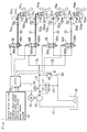
- the suspension apparatus 10 is constructed as a fluid pressure suspension utilizing a fluid pressure cylinder.
- the suspension apparatus 10 is provided with actuators 11i (11FL, 11FR, 11RL, and 11RR) for a left front wheel WFL, a right front wheel WFR, a left rear wheel WRL, and a right rear wheel WRR.
- actuators 11i 11FL, 11FR, 11RL, and 11RR for a left front wheel WFL, a right front wheel WFR, a left rear wheel WRL, and a right rear wheel WRR.
- the subscript 'i' arbitrarily represents FL, FR, RL, and RR corresponding to the respective wheels.
- the actuator 11i which is a cylinder piston device, is interposed between the vehicle body and a suspension member 12i for supporting the corresponding wheel (that is, between the vehicle body and each wheel) to suspend the vehicle body.
- the actuator 11i vertically moves the piston every time when a working fluid (oil in this embodiment) is fed to or discharged from a working fluid chamber, so as to change the vehicle height along the vertical axis at the corresponding wheel.
- a damping force varying mechanism 15i including an accumulator 13i and a variable restrictor 14i is disposed in the flow path before each actuator 11i. The damping force varying mechanism 15i enables the actuator 11i to vary the damping force against the vertical movement of the vehicle body.
- the suspension apparatus 10 further includes a reserve tank 16 for storing oil, which is fed to and discharged from the respective actuators 11i from and to the reserve tank 16 in the following manner.
- Oil stored in the reserve tank 16 is drawn through a suction pipe 21 by a pump 20 driven by a motor 18 and fed under pressure to the constituents in the flow path after the pump 20.
- the oil drawn by the pump 20 is flown through a main supply conduit 23 via a first check valve 22 and reaches a front-wheel supply conduit 24 and a rear-wheel supply conduit 25 which are branched off from the main supply conduit 23.
- the front-wheel supply conduit 24 further branches off to a left front-wheel conduit 30 and a right front-wheel conduit 31.
- a first front-wheel control valve 26 for adjusting the vehicle height at the left front wheel WFL is disposed in the left front-wheel conduit 30, whereas a second front-wheel control valve 126 for adjusting the vehicle height at the right front wheel WFR is disposed in the right front-wheel conduit 31.
- the rear-wheel supply conduit 25 further branches off to a left rear-wheel conduit 32 and a right rear-wheel conduit 33.
- a first rear-wheel control valve 28 for adjusting the vehicle height at the left rear wheel WRL is disposed in the left rear-wheel conduit 32, whereas a second rear-wheel control valve 128 for adjusting the vehicle height at the right rear wheel WRR is disposed in the right rear-wheel conduit 33.
- Portions of the left front-wheel conduit 30 and the right front-wheel conduit 31, that is, pathways from the respective front-wheel control valves 26 and 126 to the actuators 11i, are formed to have a greater diameter than that of the left rear-wheel conduit 32 and the right rear-wheel conduit 33. It is preferable that the effective diameter of the left front-wheel conduit 30 and the right front-wheel conduit 31 is greater than that of the left rear-wheel conduit 32 and the right rear-wheel conduit 33 by 10 to 20%.
- the first front-wheel control valve 26 is a two-position selector valve selectively switched between a two-way connecting position 26a and a single-way connecting position 26b.
- the flow path of the conduits before and after the front-wheel control valve 26 is open in both directions.
- the oil flow from the pump 20 is shut off while the oil flow from the actuator 11i is allowed only under a predetermined or greater pressure.
- the first front-wheel control valve 26 is kept in the single-way connecting position 26b shown in Fig. 1 in the ordinary state and changed to the two-way connecting position 26a at the time of adjusting the vehicle height (that is, at the time of raising or lowering the vehicle height).
- the second front-wheel control valve 126 and the rear-wheel control valves 28 and 128 have structures similar to that of the first front-wheel control valve 26.
- the suspension apparatus 10 includes a drain pipe 40 and a discharge control valve 41 as a mechanism for discharging oil from the actuators 11i to lower the vehicle height.
- the drain pipe 40 is branched off from the main supply conduit 23 to reach the reserve tank 16, and is opened and closed by the discharge control valve 41.
- the discharge control valve 41 is a two-position selector valve actuated with a pressure of the flow path before the first check valve 22 as a pilot pressure.
- the discharge control valve 41 is switched from an opening position shown in Fig. 1 to a closing position in order to close the drain pipe 40 at the time of driving the pump 20, that is, at the time of increasing the vehicle height.
- the discharge control valve 41 is at the opening position shown in Fig. 1 to open the drain pipe 40.
- oil working fluid
- the front-wheel control valves 26 and 126 and the rear-wheel control valves 28 and 128 are also switched independently, and the vehicle height can thus be decreased separately at each wheel.
- the vehicle height is maintained by switching the front-wheel control valves 26 and 126 and the rear-wheel control valves 28 and 128 to the single-way connecting positions 26b, 126b, 28b, and 128b as discussed above. In this state, the motor 18 is at a stop.
- the suspension apparatus 10 is also provided with a reflux conduit 50 that is branched off from the main supply conduit 23 and joins the drain pipe 40.
- the reflux conduit 50 forcibly returns oil into the reserve tank 16 when the pressure in the main supply conduit 23 unintentionally increases.
- the reflux conduit 50 is opened and closed by a relief valve 51.
- the relief valve 51 closes the flow path of the reflux conduit 50 in the ordinary state and is actuated with an increase in pressure in the main supply conduit 23 to connect the reflux conduit 50 to the drain pipe 40.
- oil is not supplied to the actuators 11i but is returned into the reserve tank 16. This structure prevents oil from being fed to the actuators 11i at the unintentionally high pressure and thereby protects the actuators 11i from damages.
- the suspension apparatus 10 has vehicle height sensors 52i corresponding to the respective actuators 11i.
- the vehicle height sensor 52i measures the vehicle height at each wheel and outputs a detection signal representing an observed vehicle height hi to an electronic control unit (ECU) 60.
- ECU electronice control unit
- the ECU 60 is constructed as a microcomputer including a CPU, a ROM, a RAM, and a timer, and receives signals output from a group of sensors and switches 61 and signals from a pressure sensor 62 that measures the pressure in the main supply conduit 23.
- the group of sensors and switches 61 include a steering angle sensor, a vehicle speed sensor, a vertical acceleration (vertical G) sensor, a vehicle height setting switch, a brake sensor, and an ignition switch (IGSW switch), in addition to the vehicle height sensors 52i for the respective wheels.
- the ECU 60 outputs a variety of driving signals required for the adjustment of the vehicle height to the front-wheel control valves 26 and 126, the rear-wheel control valves 28 and 128, and the motor 18, in response to these input signals.
- the ECU 60 is further connected to the variable restrictors 14i of the damping force varying mechanisms 15i and regulates the openings of the variable restrictors 14i, so as to enable the actuators 11i to vary the damping force.
- the driver operates the vehicle height setting switch to select the level of the vehicle height among the alternatives of HIGH, NORMAL, and LOW and outputs a signal representing the selected level of the vehicle height. It is desirable to maintain the actual height of the vehicle at the level selected by the vehicle height setting switch, that is, at a standard vehicle height.
- the vehicle height setting switch may be replaced by a switch for setting a vehicle height mode. When a HIGH mode is selected, the switch outputs a signal to set the vehicle height at the HIGH level under an ordinary driving condition and outputs a signal to set the vehicle height at the NORMAL level under a high-speed driving condition.
- the switch When a NORMAL mode is selected, on the other hand, the switch outputs a signal to set the vehicle height at the NORMAL level under the ordinary driving condition and outputs a signal to set the vehicle height at the LOW level under the high-speed driving condition.
- the standard vehicle height is selected according to the vehicle speed among the alternatives of HIGH, NORMAL, and LOW.
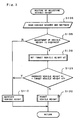
- Fig. 2 is a flowchart showing a routine of adjusting the vehicle height executed by the ECU 60.
- the routine of adjusting the vehicle height shown by the flowchart of Fig. 2 starts immediately after an operation of the IGSW switch and is repeatedly executed at predetermined time intervals.
- a known initialization process for example, clearing a flag as discussed later, is carried out immediately after each operation of the IGSW switch.
- the ECU 60 first scans the variety of sensors and switches mentioned above and reads the signals required for the adjustment of the vehicle height at step S100.
- the signals input at step S100 include data of vehicle speed measured by the vehicle speed sensor, data of vehicle height hi (that is, a vehicle height hFL at the left front wheel, a vehicle height hFR at the right front wheel, a vehicle height hRL at the left rear wheel, and a vehicle height hRR at the right rear wheel) measured by the vehicle height sensors 52i, a signal output from the brake switch to represent operation or non-operation of a foot brake, data of steering angle measured by the steering angle sensor, and a vehicle height setting signal output from the vehicle height setting switch.
- Required signal processing for example, calculation of the steering angular velocity from the input data of steering angle) is carried out with the scan.
- the ECU 60 determines whether or not the adjustment of the vehicle height is required at step S105, based on the various input signals.
- the vehicle is in the state of an abrupt turn or in the state of a high-speed turn, the vehicle is significantly rolled. The adjustment of the vehicle height under such conditions leads to deterioration of the driving stability and is thus not desirable.
- the program does not carry out any adjustment of the vehicle height but proceeds to step S110 to maintain the vehicle height at the moment.
- the ECU 60 outputs switching signals to the front-wheel control valves 26 and 126 and the rear-wheel control valves 28 and 128 to switch these control valves 26, 126, 28, and 128 to the respective single-way connecting positions 26b, 126b, 28b, and 128b and outputs a stop signal to the motor 18, thereby maintaining the vehicle height in the manner discussed previously.
- the program then exits from the vehicle height adjustment routine.
- step S105 the program proceeds to step S120, at which the ECU 60 sets a target vehicle height hT, which is the target of the vehicle height adjustment, for example, based on the vehicle speed at the moment and the vehicle height setting signal (standard vehicle height hH) output from the vehicle height setting switch. It is then determined whether or not the observed vehicle height hi coincides with the target vehicle height hT at step S125.
- the vehicle height can be adjusted independently for the left and right front wheels and for the left and right rear wheels.
- the mean value of the left front-wheel vehicle height hFL and the right front-wheel vehicle height hFR is used as the observed vehicle height hi for the determination.
- the mean value of the left rear-wheel vehicle height hRL and the right rear-wheel vehicle height hRR is used as the observed vehicle height hi for the determination.
- the observed vehicle height hi is determined to coincide with the target vehicle height hT when the observed vehicle height hi is within a predetermined range around the target vehicle height hT (that is, the target vehicle height hT ⁇ e).
- the program determines no requirement for the adjustment of the vehicle height and proceeds to step S110 to maintain the vehicle height at the moment.
- the answer at step S125 is not affirmative but negative.
- the subsequent process is varied depending upon the direction of the vehicle height adjustment, that is, either the increase in vehicle height or the decrease in vehicle height, and the difference between the front-wheel vehicle height and the rear-wheel vehicle height as described below.
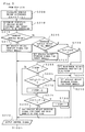
- Fig. 3 is a flowchart showing details of the process of the vehicle height adjustment carried out at step S130.
- the ECU 60 When the program enters the routine of Fig. 3, the ECU 60 first calculates a vehicle height difference or deviation ⁇ h of the observed vehicle height hi from the target vehicle height hT for each wheel at step S200, and determines the direction of the vehicle height adjustment (increase or decrease in vehicle height) and the target wheels to be controlled, based on the calculated vehicle height difference ⁇ h at step S210. At a decision point S215, it is determined whether the result of determination at step S210 represents an increase in vehicle height.
- the ECU 60 sets a control signal (vehicle height increase signal) required for raising the vehicle height at the target wheels to be controlled at step S217, and outputs the control signal to the control valves corresponding to the target wheels at step S220, so as to supply the oil to the actuators 11i for the target wheels and thereby increase the vehicle height at the target wheels.
- a control signal vehicle height increase signal
- the ECU 60 outputs a control signal to the motor 18 in order to drive the motor 18, while outputting switching signals to the control valves corresponding to the target wheels to be controlled, for example, the rear-wheel control valves 28 and 128 for the left and right rear wheels, in order to switch the control valves 28 and 128 to the respective two-way connecting positions 28a and 128a.
- This procedure enables the oil to be supplied to the actuators 11i corresponding to the rear wheels, thereby increasing the vehicle height.
- the time period for which the rear-wheel control valves 28 and 128 are kept in the two-way connecting positions 28a and 128a that is, the control amount for increase in vehicle height, depends upon the vehicle height difference ⁇ h.
- the control amount for increase in vehicle height corresponding to the calculated vehicle height difference ⁇ h is read from a map that has been prepared in advance and stored in the RAM.
- the ECU 60 outputs the control signals to the front-wheel control valves 26 and 126 at a different timing after outputting the control signals to the rear-wheel control valves 28 and 128. This procedure ensures that the increase in vehicle height at the rear wheels is always carried out prior to the increase in vehicle height at the front wheels.
- step S225 determines whether or not the decrease in vehicle height is required for all the wheels based on the result of determination at step S210.
- the ECU 60 sets a control signal (vehicle height decrease signal) required for lowering the vehicle height at the target wheel to be controlled at step S227, and outputs the control signal to the control valve corresponding to the target wheel at step S220, so as to discharge the oil from the actuator 11i for the target wheel, for example, the actuator 11FL for the left front wheel WFL, and thereby decrease the vehicle height at the target wheel.
- a control signal vehicle height decrease signal
- the ECU 60 outputs a control signal to the motor 18 in order to stop the operation of the motor 18, while outputting a switching signal to the front-wheel control valve 26 in order to switch the control valve 26 to the two-way connecting position 26a.
- This procedure enables the oil to be discharged from the actuator 11FL corresponding to the left front wheel WFL, thereby lowering the vehicle height at the left front wheel WFL.
- the time period for which the front-wheel control valve 26 is kept in the two-way connecting position 26a that is, the control amount for decrease in vehicle height, also depends upon the vehicle height difference ⁇ h.
- the ECU 60 compares a front-wheel vehicle height HF (that is, the average of a left front-wheel vehicle height hFL and a right front-wheel vehicle height hFR) with a rear-wheel vehicle height HR (that is, the average of a left rear-wheel vehicle height hRL and a right rear-wheel vehicle height hRR) to determine whether or not the front-wheel vehicle height HF is lower than the rear-wheel vehicle height HR at step S235.
- a front-wheel vehicle height HF that is, the average of a left front-wheel vehicle height hFL and a right front-wheel vehicle height hFR
- a rear-wheel vehicle height HR that is, the average of a left rear-wheel vehicle height hRL and a right rear-wheel vehicle height hRR
- a flag for prohibiting the decrease in vehicle height at the rear wheels (a rear-wheel height decrease prohibition flag FSTOP) is set equal to one, in order to delay the decrease in vehicle height at the rear wheels at step S240.
- the ECU 60 sets a control signal (vehicle height decrease signal) required for lowering the vehicle height at the front wheels at step S250, and outputs the control signal to the control valves corresponding to the front wheels at step S220.
- step S250 follows the affirmative answer at step S225 (that is, determination that the decrease in vehicle height is required for all the wheels), the negative answer at step S235, and the prohibition of decrease in vehicle height at the rear wheels at step S240.
- the control signal is accordingly set at step S250 to lower the vehicle height at the left front wheel WFL and the right front wheel WFR.
- step S220 the ECU 60 stops operation of the motor 18 and switches the front-wheel control valves 26 and 126 to the respective two-way connecting positions 26a and 126a, thereby lowering the vehicle height at the left front wheel WFL and the right front wheel WFR.
- the program lowers the vehicle height only at the front wheels while not carrying out the decrease in vehicle height at the rear wheels.
- the time period for which the front-wheel control valves 26 and 126 are kept in the two-way connecting positions 26a and 126a, that is, the control amount for decrease in vehicle height also depends upon the vehicle height difference ⁇ h.
- the rear-wheel height decrease prohibition flag FSTOP is equal to one at step S255.
- the value of the flag represents whether the decrease in vehicle height is being carried out or prohibited at the rear wheels.
- the flag FSTOP 1 means that the front-wheel vehicle height HF has been determined to be higher than the rear-wheel vehicle height HR and the program has carried out the decrease in vehicle height at the front wheels while delaying or prohibiting the decrease in vehicle height at the rear wheels in the previous cycle of this routine. In this case, the vehicle height has been lowered only at the front wheels in the previous cycle of this routine, and the answer at step S235 is accordingly affirmative (front-wheel vehicle height HF ⁇ rear-wheel vehicle height HR) in the current cycle of this routine.
- the affirmative answer (front-wheel vehicle height HF ⁇ rear-wheel vehicle height HR) is also given at step S235 when the decrease in vehicle height has been started simultaneously at the front wheels and at the rear wheels or when the decrease in vehicle height continues or is being carried out simultaneously at the front wheels and at the rear wheels under the condition that the front-wheel vehicle height HF is lower than the rear-wheel vehicle height HR.
- the answer at step S255 determines whether the affirmative answer at step S235 corresponds to the former case, in which the program has carried out the decrease in vehicle height only at the front wheels while prohibiting the decrease in vehicle height at the rear wheels, or the latter case, in which the decrease in vehicle height has been started simultaneously or continues simultaneously at the front wheels and at the rear wheels.
- step S255 On the contrary, the decrease in vehicle height has been started simultaneously or continues simultaneously at the front wheels and at the rear wheels. In the latter case, the program proceeds to step S275 described below.
- the program carries out the following procedure to specify a timing for starting the decrease in vehicle height at the rear wheels, which has been once prohibited.
- the ECU 60 first determines whether or not the front-wheel vehicle height HF is lower than the rear-wheel vehicle height HR at least by a predetermined value ⁇ (for example, 10 mm) at step S265.
- the affirmative answer at step S265 means that the decrease in vehicle height carried out only at the front wheels has sufficiently lowered the vehicle height at the front wheels than that at the rear wheels.
- the program goes to step S270 to set the rear-wheel height decrease prohibition flag FSTOP is set equal to zero, so as to cancel the prohibition and enable the decrease in vehicle height at the rear wheels.
- the program determines that the front-wheel vehicle height HF is not sufficiently lower than the rear-wheel vehicle height HR and proceeds to steps S250 and S220 to continue lowering the vehicle height only at the front wheels while prohibiting the decrease in vehicle height at the rear wheels.
- the rear-wheel height decrease prohibition flag FSTOP is kept equal to one, because of the affirmative answer at step S255.
- step S275 After the processing at step S270 to enable the decrease in vehicle height at the rear wheels, the program proceeds to step S275.
- the processing of step S275 is carried out after the affirmative answer at step S235 (front-wheel vehicle height HF ⁇ rear-wheel vehicle height HR) and the affirmative answer at step S265 ( front-wheel vehicle height HF ⁇ rear-wheel vehicle height - ⁇ ), that is, when the rear-wheel vehicle height HR is sufficiently higher than the front-wheel vehicle height HF and the decrease in vehicle height is allowed at the rear wheels.
- the rear-wheel vehicle height HR may become equal to or lower than the front-wheel vehicle height HF.
- the affirmative answer at step S275 means that the rear-wheel vehicle height HR comes excessively close to the front-wheel vehicle height HF and there is a fear of making the rear-wheel vehicle height HR equal to or even lower than the front-wheel vehicle height HF.
- the ECU 60 sets the rear-wheel height decrease prohibition flag FSTOP equal to one, in order to temporarily interrupt the further decrease in vehicle height at the rear wheels at step S280.
- the program then proceeds to steps S250 and S220 to continue lowering the vehicle height only at the front wheels.
- the negative answer at step S275 means, on the other hand, that the rear-wheel vehicle height HR is sufficiently apart from the front-wheel vehicle height HF and there is no fear of making the rear-wheel vehicle height HR equal to or lower than the front-wheel vehicle height HF.
- the ECU 60 sets a control signal (vehicle height decrease signal) required for lowering the vehicle height simultaneously at the front wheels and at the rear wheels at step S290, and outputs the control signal to the control valves corresponding to both the front wheels and the rear wheels at step S220.
- the ECU 60 outputs a control signal to the motor 18 in order stop the operation of the motor 18, while outputting switching signals to all the front-wheel control valves 26 and 126 and the rear-wheel control valves 28 and 128 in order to switch these control valves 26, 126, 28, and 128 to the respective two-way connecting positions 26a, 126a, 28a, and 128a.
- This procedure enables the oil to be discharged from the actuators 11i corresponding to both the front wheels and the rear wheels, thereby lowering the vehicle height simultaneously at the front wheels and the rear wheels.
- the left front-wheel conduit 30 and the right front-wheel conduit 31, which function as discharge conduits of oil from the actuators 11FL and 11FR corresponding to the left front wheel WFL and the right front wheel WFR, have the greater effective diameters than those of the left rear-wheel conduit 32 and the right rear-wheel conduit 33 for the left rear wheel WRL and the right rear wheel WRR.
- the flow resistance in the left front-wheel conduit 30 and the right front-wheel conduit 31 is accordingly smaller than that in the left rear-wheel conduit 32 and the right rear-wheel conduit 33. This means that oil is discharged from the actuators 11FL and 11FR corresponding to the front wheels at a greater rate than that from the actuators 11RL and 11RR corresponding to the rear wheels.
- the program After enhancing the discharge rate of oil at the front wheels, the program carries out the processing of steps S290 and S220 to output control signals simultaneously to the front-wheel control valves 26 and 126 and the rear-wheel control valves 28 and 128 and enable oil to be simultaneously discharged from the actuators 11i corresponding to the front wheels and the rear wheels.
- the decrease in vehicle height at the front wheels is thus carried out simultaneously with the decrease in vehicle height at the rear wheels.
- the greater discharge rate of oil at the front wheels ensures that the vehicle height at the front wheels is lowered at a higher rate than that at the rear wheels. This effectively prevents the vehicle height at the front wheels from being higher than the vehicle height at the rear wheels in the course of lowering the vehicle height.
- the simultaneous decrease in vehicle height at the front wheels and at the rear wheels does not require any wait time to delay the procedure of lowering the vehicle height either at the front wheels or at the rear wheels.
- the structure of the suspension apparatus 10 of the first embodiment effectively prevents the head lamps from turning upward and blinding the driver in a vehicle running in the opposite direction in the course of lowering the vehicle height. This structure also shortens the time period required for completing the decrease in vehicle height.
- the suspension apparatus 10 of the embodiment has the following effects.
- the simultaneous decrease in vehicle height at the front wheels and at the rear wheels is carried out after the affirmative answer at step S235 and the negative answer at step S275 as discussed previously. While the decrease in vehicle height at the front wheels continues irrespective of the affirmative or negative answer at step S235, the decrease in vehicle height at the rear wheels may be delayed (at step S240) or temporarily interrupted (at step S280) based on the result of comparison between the front-wheel vehicle height HF and the rear-wheel vehicle height HR.
- the suspension apparatus 10 of the first embodiment can thus be modified as discussed below.
- a modified structure wherein the left front-wheel conduit 30 and the right front-wheel conduit 31 have the effective diameters identical with those of the left rear-wheel conduit 32 and the right rear-wheel conduit 33, also carries out the vehicle height adjustment routine shown in the flowcharts of Figs. 2 and 3.
- the suspension apparatus 10 of modified structure can exert the same effects as those described above, that is, preventing the head lamps from turning upward and blinding the driver in a vehicle running in the opposite direction in the course of lowering the vehicle height and shortening the required time period for completing the decrease in vehicle height.
- the suspension apparatus 10 of modified structure continues the oil discharge from the actuators 11FL and 11FR for the front wheels, so as to continuously lower the vehicle height at the front wheels. While the oil discharge from the actuators 11FL and 11FR for the front wheels continues, the negative answer at step S275 starts and continues the oil discharge from the actuators 11RL and 11RR for the rear wheels. Even when the left front-wheel conduit 30 and the right front-wheel conduit 31 have the effective diameters identical with those of the left rear-wheel conduit 32 and the right rear-wheel conduit 33, this procedure enables the simultaneous decrease in vehicle height at the front wheels and at the rear wheels only after the decrease in vehicle height at the front wheels.
- the suspension apparatus 10 of modified structure thus effectively prevents the head lamps from turning upward and blinding the driver in a vehicle running in the opposite direction in the course of lowering the vehicle height.
- the decrease in vehicle height at the rear wheels is carried out simultaneously with the decrease in vehicle height at the front wheels after a start of oil discharge from the actuators 11RL and 11RR for the rear wheels. This structure shortens the required time period for completing the decrease in vehicle height.
- the suspension apparatus 10 of modified structure can also exert the effects (1) and (2) mentioned above.
- suspension apparatus 10A as a second embodiment according to the present invention.
- the same constituents as those of the suspension apparatus 10 of the first embodiment are shown by the like numerals and symbols and not specifically described here.
- Fig. 4 schematically illustrates a fluid circuit in the suspension apparatus 10A of the second embodiment.
- the suspension apparatus 10A has different circuit structures at the front wheels and at the rear wheels.
- the suspension apparatus 10A has the front-wheel supply conduit 24 and the rear-wheel supply conduit 25 which are branched off from the main supply conduit 23.
- a front-wheel control valve 26 for adjusting the vehicle height at the left and the right front wheels WFL and WFR and a front-wheel connection control valve 27 for switching the actuators 11FL and 11FR corresponding to the left front wheel WFL and the right front wheel WFR between a connecting position and a disconnecting position are arranged in series in this sequence in the front-wheel supply conduit 24.
- a rear-wheel control valve 28 for adjusting the vehicle height at the left and the right rear wheels WRL and WRR is disposed in the rear-wheel supply conduit 25, which further branches off at the rear-wheel control valve 28 to a left rear-wheel conduit 32 and a right rear-wheel conduit 33.
- a rear-wheel connection control valve 29 for switching the actuators 11RL and 11RR corresponding to the left rear wheel WRL and the right rear wheel WRR between a connecting position and a disconnecting position is arranged in the right rear-wheel conduit 33.
- An orifice 32a ensuring a similar flow resistance to that of the orifice included in the rear-wheel connection control valve 29 is disposed in the left rear-wheel conduit 32.
- the front-wheel control valve 26, the front-wheel connection control valve 27, the rear-wheel control valve 28, and the rear-wheel connection control valve 29 are two-position selector valves selectively switched between two-way connecting positions 26a through 29a and single-way connecting positions 26b through 29b.
- the front-wheel control valve 26 and the rear-wheel control valve 28 are kept in the single-way connecting positions 26b and 28b shown in Fig. 4 in the ordinary state and changed to the two-way connecting positions 26a and 28a at the time of adjusting the vehicle height (at the time of raising or lowering the vehicle height).
- the front-wheel connection control valve 27 and the rear-wheel connection control valve 29 are, on the other hand, kept in the two-way connecting positions 27a and 29a shown in Fig. 4 in the ordinary state and changed to the single-way connecting positions 27b and 29b at a turn of the vehicle.
- the front-wheel supply conduit 24 is branched off at a diverging point 24a after the front-wheel connection control valve 27 to a left front-wheel conduit 30 connecting with the actuator 11FL for the left front wheel WFL and a right front-wheel conduit 31 connecting with the actuator 11FR for the right front wheel WFR.
- the rear-wheel supply conduit 25 is branched off at a diverging point 25a before the rear-wheel connection control valve 29 to the left rear-wheel conduit 32 and the right rear-wheel conduit 33.
- oil flown into the front-wheel supply conduit 24 passes through the front-wheel control valve 26 and the subsequent front-wheel connection control valve 27 and is fed to the actuators 11FL and 11FR via check valves 35 and 36 for raising the vehicle height, which are disposed respectively in the left front-wheel conduit 30 and the right front-wheel conduit 31.
- oil flown into the rear-wheel supply conduit 25 passes through the rear-wheel control valve 28 and then flows into the left rear-wheel conduit 32 and the right rear-wheel conduit 33 that are branched off at the diverging point 25a.
- Oil is supplied to the actuator 11RL via the orifice 32a in the left rear-wheel conduit 32 and supplied to the actuator 11RR via the rear-wheel connection control valve 29 switched to the two-way connecting position 29a.
- the vehicle height is accordingly raised at the wheels corresponding to the actuators 11i that receive the supply of oil.
- the front-wheel control valve 26 and the rear-wheel control valve 28 are switched independently, and the vehicle height can thus be increased only at the left and right front wheels, only at the left and right rear wheels, or at all the wheels of the vehicle.
- the suspension apparatus 10A of the second embodiment includes a drain pipe 40 and a discharge control valve 41 for opening and closing the drain pipe 40 as a mechanism for discharging oil from the actuators 11i to lower the vehicle height.
- the suspension apparatus 10A further includes by-passes for the actuators 11FL and 11FR corresponding to the left and right front wheels WFL and WFR as another mechanism for lowering the vehicle height.
- the suspension apparatus 10A has a left front-wheel by-pass 42 and a check valve 43 for lowering the vehicle height with respect to the actuator 11FL.
- the left front-wheel by-pass 42 is branched off from the left front-wheel conduit 30 at a diverging point 30a and by-passes the front-wheel connection control valve 27 to reach a diverging point 24b before the front-wheel connection control valve 27.
- the check valve 43 is disposed in the left front-wheel by-pass 42 to allow an oil flow only from the left front-wheel conduit 30 to the front-wheel supply conduit 24.
- the suspension apparatus 10A has a right front-wheel by-pass 44, which is branched off from the right front-wheel conduit 31 at a diverging point 31a and by-passes the front-wheel connection control valve 27 to reach the diverging point 24b before the front-wheel connection control valve 27, and a check valve 45 for lowering the vehicle height, which is disposed in the right front-wheel by-pass 44 to allow an oil flow only from the right front-wheel conduit 31 to the front-wheel supply conduit 24.
- the suspension apparatus 10A thus constructed enables oil to be discharged from the actuators 11i, in order to lower the vehicle height in the manner discussed below.
- the flow relating to the actuator 11FL is described below as an example for the front wheels.
- Oil in the actuator 11FL is discharged to the left front-wheel conduit 30 by the internal pressure of the actuator 11FL.
- the check valve 35 for raising the vehicle height works to prevent the oil flow to the diverging point 24a but enables the oil flow from the diverging point 30a to the left front-wheel by-pass 42. Since the check valve 43 for lowering the vehicle height disposed in the left front-wheel by-pass 42 allows the oil flow only from the left front-wheel by-pass 42 to the diverging point 24b of the front-wheel supply conduit 24, oil discharged from the actuator 11FL by-passes the front-wheel connection control valve 27 and is flown out of the left front-wheel by-pass 42 to the front-wheel supply conduit 24.
- the front-wheel control valve 26 is at the two-way connecting position 26a in this state as discussed above, and oil is accordingly flown via the front-wheel control valve 26 to the main supply conduit 23.
- the pump 20 is stopped and the discharge control valve 41 opens the drain pipe 40 at the time of lowering the vehicle height. Oil discharged from the actuator 11FL thus passes through the drain pipe 40 and is returned to the reserve tank 16 for recycling. This procedure lowers the vehicle height at the left front wheel WFL. This procedure is also applied to the right front wheel WFR.
- oil is discharged from the actuators 11RL and 11RR to the left rear-wheel conduit 32 and the right rear-wheel conduit 33 and flown into the rear-wheel supply conduit 25 after the orifice 32a and the rear-wheel connection control valve 29.
- the oil then passes through the main supply conduit 23 and the drain pipe 40 and is eventually returned to the reserve tank 16 for recycling. This procedure lowers the vehicle height at the left rear wheel WRL and the right rear wheel WRR.
- the vehicle height is maintained by switching the front-wheel control valve 26 and the rear-wheel control valve 28 to the single-way connecting positions 26b and 28b as discussed previously. In this state, the motor 18 is at a stop.
- the suspension apparatus 10A of the second embodiment also carries out the vehicle height adjustment routine shown in the flowcharts of Figs. 2 and 3.
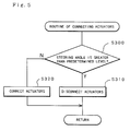
- the routine of connecting the actuators shown in the flowchart of Fig. 5 is executed to depress an increase in rolling angle caused by the turn.
- the actuators connecting routine is also executed repeatedly at predetermined time intervals. The preference in interruption is determined in advance and given to either the vehicle height adjustment routine or the actuators connecting routine.
- the ECU 60 When the program enters the actuators connecting routine shown in the flowchart of Fig. 5, the ECU 60 first determines whether or not the data of steering angle obtained from the steering angle sensor is equal to or greater than a predetermined value at step S300. The determination of step S300 may alternatively be based on the data of steering angular velocity. When the answer is affirmative at step S300, the program determines that the vehicle is in the state of a large turn or an abrupt turn and proceeds to step S310 to disconnect the actuators 11FL and 11FR for the front wheels from each other and to disconnect the actuators 11RL and 11RR for the rear wheels from each other.
- the ECU 60 outputs switching signals to the front-wheel connection control valve 27 and the rear-wheel connection control valve 29 to switch these connection control valves 27 and 29 to the respective single-way connecting positions 27b and 29b.
- the front-wheel connection control valve 27 is switched to the single-way connecting position 27b, the oil flow from the actuator 11FL to the actuator 11FR and the reversed oil flow are blocked by the check valves 35 and 36 for raising the vehicle height and the connection control valve 27 at the single-way connecting position 27b. This process results in disconnecting the actuators 11FL and 11FR from each other.
- the switching operation of the rear-wheel connection control valve 29 to the single-way connecting position 29b blocks the oil flows and thereby disconnects the actuators 11RL and 11RR.
- step S320 When the answer is negative at step S300, on the contrary, the program proceeds to step S320 to connect the actuators 11FL and 11FR for the front wheels with each other and to connect the actuators 11RL and 11RR for the rear wheels with each other.
- the ECU 60 outputs switching signals to the front-wheel connection control valve 27 and the rear-wheel connection control valve 29 to switch these connection control valves 27 and 29 to the respective two-way connecting positions 27a and 29a.
- the check valve 43 for lowering the vehicle height, the connection control valve 27 at the two-way connecting position 27a, and the check valve 36 for raising the vehicle height function to connect the left front-wheel conduit 30 successively to the left front-wheel by-pass 42, the front-wheel supply conduit 24, and the right front-wheel conduit 31 and form the oil flow path from the actuator 11FL to the actuator 11FR.
- the check valve 45 for lowering the vehicle height, the connection control valve 27 at the two-way connecting position 27a, and the check valve 35 for raising the vehicle height function to connect the right front-wheel conduit 31 successively to the right front-wheel by-pass 44, the front-wheel supply conduit 24, and the left front-wheel conduit 30 and form the oil flow path from the actuator 11FR to the actuator 11FL. This process results in mutually connecting the actuators 11FL and 11FR with each other.
- the left rear-wheel conduit 32 and the right rear-wheel conduit 33 are connected to each other in series and mutually connect the actuators 11RL and 11RR for the rear wheels.
- This procedure appropriately connects and disconnects the actuators 11FL and 11FR (11RL and 11RR) with each other and from each other, thereby exerting the following effects.
- An extreme input of road surface causes vibrations of the left and right wheels in reversed phases along the vertical axis, and the internal pressures of the actuators for the left and right wheels are significantly varied in an alternating manner. This leads to an excessive increase in pressure in the whole system including these actuators.
- the actuators for the left and the right wheels in the connecting position enable a working fluid to be fed to the wheels on one side, in order to relieve an increase in internal pressure of the wheels on the other side, thereby depressing the increase in pressure.
- connection of the actuators ensures the sufficient grips of the left and right wheels independently, so as to improve the driving stability.
- connection of the actuators for the left and right wheels enables the internal pressures of the actuators to be substantially equal to each other after the shift to the flat road surface. This effectively prevents the attitude of the vehicle body from being unnaturally inclined.
- the actuators for the left and right wheels are in the connecting position at a turn of the vehicle, on the other hand, the rolling angle increases with an increase in steering angle. In this case, the actuators for the left and right wheels are switched to a disconnecting position, in order to depress the increase in rolling angle.
- the left front-wheel by-pass 42 and the right front-wheel by-pass 44 for by-passing the front-wheel connection control valve 27 are arranged on the side of the front wheels. This structure ensures the following effects when the vehicle height adjustment routine shown in Figs. 2 and 3 is carried out to lower the vehicle height.
- the check valve 35 for raising the vehicle height disposed after the front-wheel connection control valve 27 and the check valve 43 for lowering the vehicle height disposed in the left front-wheel by-pass 42 function to enable oil in the actuator 11FL to by-pass the front-wheel connection control valve 27 and flow successively through the left front-wheel by-pass 42, the front-wheel supply conduit 24, and the main supply conduit 23 to be returned to the reserve tank 16 for recycling.
- Oil discharged from the actuator 11FR corresponding to the right front wheel WFR by-passes the front-wheel connection control valve 27 and flows through the right front-wheel by-pass 44 and the front-wheel supply conduit 24.
- the structure that the oil flow from the actuators 11FL and 11FR by-passes the front-wheel connection control valve 27 effectively reduces the pressure loss due to the flow through the front-wheel connection control valve 27 and enhances the flow rate of oil discharge.
- the suspension apparatus 10A of the second embodiment improves the flow rate of oil discharged from the actuators 11i for the left and the right front wheels, thereby making the descending rate of the vehicle height at the front wheels higher than that at the rear wheels.
- this structure ensures a greater rate of oil discharge at the front wheels and thereby enables the vehicle height at the front wheels to decrease at a higher rate than the vehicle height at the rear wheels. This effectively prevents the vehicle height at the front wheels from being higher than the vehicle height at the rear wheels in the course of lowering the vehicle height.
- the structure of the suspension apparatus 10A of the second embodiment prevents the head lamps from turning upward and blinding the driver in a vehicle running in the opposite direction in the course of lowering the vehicle height. This structure also improves the descending rate of the vehicle height at the front wheels and thereby shortens the time period required for completing the decrease in vehicle height.
- oil discharged from the actuators 11i for the left and right front wheels flows through the check valves 43 and 45 for lowering the vehicle height.
- the check valve is not required to narrow the diameter of the oil flow path and thereby does not cause any significant pressure loss in the course of oil flow.
- the flow rate of oil passing through the check valves 43 and 45 for lowering the vehicle height is thus substantially equal to that through the front-wheel connection control valve 27.
- the present invention is not restricted to the above embodiments, but there may be many modifications, changes, and alterations without departing from the scope or spirit of the main characteristics of the present invention.
- the front-wheel control valves 26 and 126 and the rear-wheel control valves 28 and 128 may be switched between the two-way connecting position and a disconnecting position at which the flow path is completely blocked.
- the front-wheel connection control valve 27 and the rear-wheel connection control valve 29 may also have this alternative structure.
- the left front-wheel conduit 30 and the right front-wheel conduit 31 have the greater effective diameters than those of the left rear-wheel conduit 2 and the right rear-wheel conduit 33, so that the flow resistance at the front wheels is smaller than that at the rear wheels.
- the effective diameters of the orifices included in the front-wheel control valves 26 and 126 may be set greater than those in the orifices included in the rear-wheel control valves 28 and 128.
- oil discharged from actuators 11FL and 11FR corresponding to left and right front wheels flows through a left front-wheel conduit 30 and a right front-wheel conduit 31, whereas oil discharged from actuators 11RL and 11RR corresponding to left and right rear wheels flows through a left rear-wheel conduit 32 and a right rear-wheel conduit 33.
- the left front-wheel conduit 30 and the right front-wheel conduit 31 have greater effective diameters than those of the left rear-wheel conduit 32 and the right rear-wheel conduit 33.
- the flow resistance in the left front-wheel conduit 30 and the right front-wheel conduit 31 is accordingly smaller than that in the left rear-wheel conduit 32 and the right rear-wheel conduit 33. This means that oil is discharged from the actuators 11FL and 11FR corresponding to the front wheels at a greater rate than that from the actuators 11RL and 11RR corresponding to the rear wheels.
Applications Claiming Priority (3)
| Application Number | Priority Date | Filing Date | Title |
|---|---|---|---|
| JP13107796 | 1996-04-25 | ||
| JP131077/96 | 1996-04-25 | ||
| JP13107796A JPH09290614A (ja) | 1996-04-25 | 1996-04-25 | サスペンション装置 |
Publications (3)
| Publication Number | Publication Date |
|---|---|
| EP0803385A2 true EP0803385A2 (fr) | 1997-10-29 |
| EP0803385A3 EP0803385A3 (fr) | 2000-02-23 |
| EP0803385B1 EP0803385B1 (fr) | 2008-08-13 |
Family
ID=15049457
Family Applications (1)
| Application Number | Title | Priority Date | Filing Date |
|---|---|---|---|
| EP19970106842 Expired - Lifetime EP0803385B1 (fr) | 1996-04-25 | 1997-04-24 | Dispositif de suspension |
Country Status (3)
| Country | Link |
|---|---|
| EP (1) | EP0803385B1 (fr) |
| JP (1) | JPH09290614A (fr) |
| DE (1) | DE69738892D1 (fr) |
Cited By (1)
| Publication number | Priority date | Publication date | Assignee | Title |
|---|---|---|---|---|
| DE10007382A1 (de) * | 2000-02-18 | 2001-08-23 | Bayerische Motoren Werke Ag | Luftfedersystem für ein zweiachsiges Kraftfahrzeug |
Families Citing this family (1)
| Publication number | Priority date | Publication date | Assignee | Title |
|---|---|---|---|---|
| JP4760369B2 (ja) * | 2005-12-27 | 2011-08-31 | トヨタ自動車株式会社 | サスペンション装置 |
Citations (6)
| Publication number | Priority date | Publication date | Assignee | Title |
|---|---|---|---|---|
| JPS60209311A (ja) * | 1984-04-02 | 1985-10-21 | Kayaba Ind Co Ltd | 油空圧サスペンシヨン |
| JPS62122810A (ja) * | 1985-11-22 | 1987-06-04 | Showa Mfg Co Ltd | 車高調整装置 |
| EP0297736A2 (fr) * | 1987-06-29 | 1989-01-04 | General Motors Corporation | Dispositif de suspension de pneumatique pour véhicule à réglage précis du niveau d'un côté par rapport à l'autre côté |
| JPH02237811A (ja) * | 1990-02-13 | 1990-09-20 | Mitsubishi Motors Corp | 車高制御装置 |
| WO1994000307A2 (fr) * | 1992-06-23 | 1994-01-06 | Rover Group Limited | Systeme de suspension de vehicule |
| EP0791492A1 (fr) * | 1996-02-23 | 1997-08-27 | Toyota Jidosha Kabushiki Kaisha | Dispositif et méthode de réglage de la suspension |
-
1996
- 1996-04-25 JP JP13107796A patent/JPH09290614A/ja active Pending
-
1997
- 1997-04-24 DE DE69738892T patent/DE69738892D1/de not_active Expired - Lifetime
- 1997-04-24 EP EP19970106842 patent/EP0803385B1/fr not_active Expired - Lifetime
Patent Citations (6)
| Publication number | Priority date | Publication date | Assignee | Title |
|---|---|---|---|---|
| JPS60209311A (ja) * | 1984-04-02 | 1985-10-21 | Kayaba Ind Co Ltd | 油空圧サスペンシヨン |
| JPS62122810A (ja) * | 1985-11-22 | 1987-06-04 | Showa Mfg Co Ltd | 車高調整装置 |
| EP0297736A2 (fr) * | 1987-06-29 | 1989-01-04 | General Motors Corporation | Dispositif de suspension de pneumatique pour véhicule à réglage précis du niveau d'un côté par rapport à l'autre côté |
| JPH02237811A (ja) * | 1990-02-13 | 1990-09-20 | Mitsubishi Motors Corp | 車高制御装置 |
| WO1994000307A2 (fr) * | 1992-06-23 | 1994-01-06 | Rover Group Limited | Systeme de suspension de vehicule |
| EP0791492A1 (fr) * | 1996-02-23 | 1997-08-27 | Toyota Jidosha Kabushiki Kaisha | Dispositif et méthode de réglage de la suspension |
Non-Patent Citations (3)
| Title |
|---|
| PATENT ABSTRACTS OF JAPAN vol. 010, no. 062 (M-460), 12 March 1986 (1986-03-12) & JP 60 209311 A (KAYABA KOGYO KK), 21 October 1985 (1985-10-21) * |
| PATENT ABSTRACTS OF JAPAN vol. 011, no. 344 (M-640), 11 November 1987 (1987-11-11) & JP 62 122810 A (SHOWA MFG CO LTD), 4 June 1987 (1987-06-04) * |
| PATENT ABSTRACTS OF JAPAN vol. 014, no. 556 (M-1057), 11 December 1990 (1990-12-11) & JP 02 237811 A (MITSUBISHI MOTORS CORP;OTHERS: 01), 20 September 1990 (1990-09-20) * |
Cited By (3)
| Publication number | Priority date | Publication date | Assignee | Title |
|---|---|---|---|---|
| DE10007382A1 (de) * | 2000-02-18 | 2001-08-23 | Bayerische Motoren Werke Ag | Luftfedersystem für ein zweiachsiges Kraftfahrzeug |
| US6513820B2 (en) | 2000-02-18 | 2003-02-04 | Bayerische Motoren Werke Aktiengesellschaft | Air spring system for a two axle motor vehicle |
| EP1125776A3 (fr) * | 2000-02-18 | 2004-07-28 | Bayerische Motoren Werke Aktiengesellschaft | Système à ressort pneumatique pour un véhicule à deux essieux |
Also Published As
| Publication number | Publication date |
|---|---|
| JPH09290614A (ja) | 1997-11-11 |
| EP0803385B1 (fr) | 2008-08-13 |
| EP0803385A3 (fr) | 2000-02-23 |
| DE69738892D1 (de) | 2008-09-25 |
Similar Documents
| Publication | Publication Date | Title |
|---|---|---|
| KR910006823B1 (ko) | 차량용 현수 장치 | |
| US5701245A (en) | Suspension control system | |
| US6098994A (en) | Vehicle height control apparatus | |
| EP0556055B1 (fr) | Système de suspension pour un véhicule automobile | |
| JPH02274607A (ja) | 流体圧式アクティブサスペンション | |
| JPH01297316A (ja) | 車両のサスペンション制御装置 | |
| EP0482237A1 (fr) | Mécanisme pour supprimer les vibrations des grues mobiles | |
| JPH02274606A (ja) | 流体圧式アクティブサスペンション | |
| JP3015514B2 (ja) | 車両のサスペンション装置 | |
| US4613154A (en) | Vehicle suspension apparatus | |
| US5228704A (en) | Vehicle height control system after ignition switch is turned off | |
| KR910002833B1 (ko) | 차량용 현수 장치 | |
| EP0803385B1 (fr) | Dispositif de suspension | |
| EP0791492B1 (fr) | Dispositif et méthode de réglage de la suspension | |
| JP3061841B2 (ja) | 車両の姿勢制御装置 | |
| KR910003764B1 (ko) | 차량용 현수장치 | |
| JP3059199B2 (ja) | 電子制御流体圧サスペンション | |
| JPH0344563Y2 (fr) | ||
| JPH066968Y2 (ja) | 車両用サスペンション装置 | |
| JPH0710889Y2 (ja) | 車高調整装置 | |
| JP2846012B2 (ja) | 車両のサスペンション装置 | |
| JP2798282B2 (ja) | 車高調整装置 | |
| JPH05193324A (ja) | 電子制御エアサスペンション車用制御装置 | |
| JP3068870B2 (ja) | 車両用制御型サスペンション | |
| JPS6296115A (ja) | 車輌用車高調整装置 |
Legal Events
| Date | Code | Title | Description |
|---|---|---|---|
| PUAI | Public reference made under article 153(3) epc to a published international application that has entered the european phase |
Free format text: ORIGINAL CODE: 0009012 |
|
| 17P | Request for examination filed |
Effective date: 19970424 |
|
| AK | Designated contracting states |
Kind code of ref document: A2 Designated state(s): DE FR GB |
|
| PUAL | Search report despatched |
Free format text: ORIGINAL CODE: 0009013 |
|
| AK | Designated contracting states |
Kind code of ref document: A3 Designated state(s): DE FR GB |
|
| 17Q | First examination report despatched |
Effective date: 20010202 |
|
| GRAP | Despatch of communication of intention to grant a patent |
Free format text: ORIGINAL CODE: EPIDOSNIGR1 |
|
| GRAS | Grant fee paid |
Free format text: ORIGINAL CODE: EPIDOSNIGR3 |
|
| GRAA | (expected) grant |
Free format text: ORIGINAL CODE: 0009210 |
|
| AK | Designated contracting states |
Kind code of ref document: B1 Designated state(s): DE FR GB |
|
| REG | Reference to a national code |
Ref country code: GB Ref legal event code: FG4D |
|
| REF | Corresponds to: |
Ref document number: 69738892 Country of ref document: DE Date of ref document: 20080925 Kind code of ref document: P |
|
| PLBE | No opposition filed within time limit |
Free format text: ORIGINAL CODE: 0009261 |
|
| STAA | Information on the status of an ep patent application or granted ep patent |
Free format text: STATUS: NO OPPOSITION FILED WITHIN TIME LIMIT |
|
| 26N | No opposition filed |
Effective date: 20090514 |
|
| REG | Reference to a national code |
Ref country code: GB Ref legal event code: 746 Effective date: 20111114 |
|
| REG | Reference to a national code |
Ref country code: DE Ref legal event code: R084 Ref document number: 69738892 Country of ref document: DE Effective date: 20111109 |
|
| PGFP | Annual fee paid to national office [announced via postgrant information from national office to epo] |
Ref country code: DE Payment date: 20120502 Year of fee payment: 16 |
|
| PGFP | Annual fee paid to national office [announced via postgrant information from national office to epo] |
Ref country code: FR Payment date: 20120504 Year of fee payment: 16 Ref country code: GB Payment date: 20120418 Year of fee payment: 16 |
|
| GBPC | Gb: european patent ceased through non-payment of renewal fee |
Effective date: 20130424 |
|
| PG25 | Lapsed in a contracting state [announced via postgrant information from national office to epo] |
Ref country code: DE Free format text: LAPSE BECAUSE OF NON-PAYMENT OF DUE FEES Effective date: 20131101 Ref country code: GB Free format text: LAPSE BECAUSE OF NON-PAYMENT OF DUE FEES Effective date: 20130424 |
|
| REG | Reference to a national code |
Ref country code: FR Ref legal event code: ST Effective date: 20131231 |
|
| REG | Reference to a national code |
Ref country code: DE Ref legal event code: R119 Ref document number: 69738892 Country of ref document: DE Effective date: 20131101 |
|
| PG25 | Lapsed in a contracting state [announced via postgrant information from national office to epo] |
Ref country code: FR Free format text: LAPSE BECAUSE OF NON-PAYMENT OF DUE FEES Effective date: 20130430 |