EP0803222A2 - Paroi de douche - Google Patents
Paroi de douche Download PDFInfo
- Publication number
- EP0803222A2 EP0803222A2 EP97104253A EP97104253A EP0803222A2 EP 0803222 A2 EP0803222 A2 EP 0803222A2 EP 97104253 A EP97104253 A EP 97104253A EP 97104253 A EP97104253 A EP 97104253A EP 0803222 A2 EP0803222 A2 EP 0803222A2
- Authority
- EP
- European Patent Office
- Prior art keywords
- connecting body
- wall elements
- seal
- shower partition
- wall element
- Prior art date
- Legal status (The legal status is an assumption and is not a legal conclusion. Google has not performed a legal analysis and makes no representation as to the accuracy of the status listed.)
- Withdrawn
Links
- 238000005192 partition Methods 0.000 claims abstract description 23
- 230000001360 synchronised effect Effects 0.000 abstract description 4
- 238000010276 construction Methods 0.000 abstract description 3
- 210000002414 leg Anatomy 0.000 description 7
- 238000007789 sealing Methods 0.000 description 4
- 238000004140 cleaning Methods 0.000 description 2
- 230000008878 coupling Effects 0.000 description 2
- 238000010168 coupling process Methods 0.000 description 2
- 238000005859 coupling reaction Methods 0.000 description 2
- 229920001971 elastomer Polymers 0.000 description 2
- 229920003023 plastic Polymers 0.000 description 2
- 244000126211 Hericium coralloides Species 0.000 description 1
- 230000002411 adverse Effects 0.000 description 1
- 238000011161 development Methods 0.000 description 1
- 230000018109 developmental process Effects 0.000 description 1
- 238000010586 diagram Methods 0.000 description 1
- 239000000806 elastomer Substances 0.000 description 1
- 238000004519 manufacturing process Methods 0.000 description 1
- 239000000463 material Substances 0.000 description 1
- 239000003973 paint Substances 0.000 description 1
- 229920001296 polysiloxane Polymers 0.000 description 1
- 230000036316 preload Effects 0.000 description 1
- 239000005368 silicate glass Substances 0.000 description 1
- 210000000689 upper leg Anatomy 0.000 description 1
- 239000002966 varnish Substances 0.000 description 1
- XLYOFNOQVPJJNP-UHFFFAOYSA-N water Substances O XLYOFNOQVPJJNP-UHFFFAOYSA-N 0.000 description 1
Images

Classifications
-
- A—HUMAN NECESSITIES
- A47—FURNITURE; DOMESTIC ARTICLES OR APPLIANCES; COFFEE MILLS; SPICE MILLS; SUCTION CLEANERS IN GENERAL
- A47K—SANITARY EQUIPMENT NOT OTHERWISE PROVIDED FOR; TOILET ACCESSORIES
- A47K3/00—Baths; Douches; Appurtenances therefor
- A47K3/28—Showers or bathing douches
- A47K3/30—Screens or collapsible cabinets for showers or baths
- A47K3/36—Articulated screens
Definitions
- the invention relates to a shower partition according to the features specified in the preamble of claim 1.
- Such a shower partition is known from DE 29 117 28 A1, which is designed as a folding wall and has at least two wall elements which can be pivoted relative to one another.
- the wall elements contain tabs connected to their respective frames, which have interlocking toothings.
- the tabs together with other tabs form hinges for the pivotable connection of the two wall elements.
- the toothing is designed in such a way that the two wall elements can be pivoted relative to one another by a predetermined angular range of 180 °.
- a flexible profile seal is arranged in the hinge area between the two wall elements, which are anchored in corresponding grooves of vertical profiles of the respective wall element.
- the wall elements contain transparent panels, which are each inserted in a frame made of vertical and horizontal frame profiles.
- the flexible profile seals mentioned are subject to considerable wear and tear and damage can already result comparatively short service life, the essential splash protection function may be adversely affected.
- the object of the invention is to further develop a shower partition of the type mentioned in such a way that a synchronous mutual pivoting of the two wall elements is made possible with a functionally reliable construction.
- the shower partition should also require as little manufacturing and assembly effort as possible and have a long service life.
- a mutual pivoting of the two wall elements by at least approximately 360 ° is to be made possible.
- the accessibility of the individual surfaces of the wall elements, especially for cleaning purposes, should be possible without any problems.
- the proposed shower partition is characterized by a simple and reliable construction and ensures a synchronous mutual rotary movement of the two hinged wall elements.
- a body having teeth is attached at the upper and / or lower end of the two adjacent rails of the two wall elements.
- two toothed wheels are expediently provided, which mesh with one another on the one hand and, on the other hand, each with the associated external teeth of the bodies mentioned.
- the teeth of the said bodies are thus only indirectly engaged via the two gear wheels, the gear wheels advantageously being spaced apart from the plane in which the axes of the external teeth are located.
- the body with the external teeth can thus have a comparatively small diameter, which ensures a compact design and an attractive design.
- a seal is arranged between the outer surfaces of the adjacent profiles.
- This seal has at least one lip, which bears on the preferably cylindrical outer surface of at least one vertical profile of the wall element. Said lip and / or the seal is also moved when the wall elements are rotated or pivoted relative to one another, the lip preferably on the cylindrical outer surface of the at least one profile is moved along. In comparison with a flexible profile seal, a considerably longer service life is ensured.
- the seal expediently encompasses the cylindrical outer surface at a predetermined circumferential angle.
- the seal is not attached directly to one of the profiles, but indirectly in a connecting body of the swivel joint.
- the seal is expediently moved by half the angle of rotation by which the two wall elements are pivoted relative to one another.
- the swivel joint ensures the mutual rotation of the wall elements by at least approximately 360 °.
- one wall element is arranged fixed on the edge of a trough, while the other wall element is pivotable essentially by 360 ° with respect to the first wall element by means of the pivot bearing according to the invention.
- the vertical profile of the first fixed wall element is also fixed and has the cylindrical outer surface already mentioned.
- the axis of rotation for the second wall element which can be pivoted synchronously about this axis of rotation by means of the toothing according to the invention, runs through the center of the first, vertical profile of the fixed wall element.
- the second pivotable wall element can thus be pivoted from a first position in parallel on the outside of the first wall element with respect to the latter by 360 ° to the inside in order to in turn be parallel to the first wall element there.
- the second rotatable wall element When not in use, the second rotatable wall element can thus easily be pivoted either inwards or outwards, so that the shower partition can be cleaned without problems.
- the swiveling second wall element can easily be swiveled into the required shower position over the edge of the tub.
- Fig. 1 shows a side view of the shower partition with two wall elements 2, 4, which are arranged over the edge 6 of a bathtub 8.
- the first wall element 2 is firmly attached to the tub rim 6 and also to a wall 10 of the bathroom.
- a ceiling support 12 is provided, by means of which the fixed wall element 2 is further stabilized.
- a bracket, elbows, stiffening brackets or the like can be provided for fastening the first wall element 2 to the wall 10 or to a further room wall which lies behind the plane of the drawing.
- the second wall element 4 is pivotably mounted with respect to the first wall element 2 by means of an upper pivot bearing 14 and a lower pivot bearing 16.
- Fig. 2 shows a top view of the two wall elements 2, 4 with the bathtub 8. It should be noted at this point that there is no restriction by the explanations of a bathtub and the shower partition according to the invention in the same way on the edge of a shower tray or directly on the Floor of a bathroom can be provided. It goes without saying that in these cases the vertical height of the wall elements 2, 4 is correspondingly enlarged.
- the second wall element 4 is in a shower position over the edge 6 of the bathtub 8. If necessary, the second wall element 4 can be pivoted further inward over the bathtub 8 according to arrow 18, a further shower position for the second wall element 4 being indicated by the dash-dotted lines is.
- the second wall element 4 can thus be pivoted into the desired shower position depending on the wishes of the user and / or depending on the design of the tub or the shower room due to the pivot bearings 14, 16 designed according to the invention.
- the arrow 20 is a further pivot angle for the second wall element 4 is indicated, which is thus pivotable to the inside with respect to the fixed wall element 2 and parallel to the latter.
- the pivotable wall element 4 can also be pivoted outward as far as arrow 22 so that it is essentially parallel to the fixed wall element 2 in front of the outside.
- the wall element 4 can be pivoted according to the three arrows 18, 20 and 22 through an angular range of 360 ° with respect to the first wall element.
- the wall element 4 When not in use, the wall element 4 is pivoted to the inside of the first wall element 2 according to the arrows 18 and 20, while, in particular for cleaning purposes, the second wall element 4 is pivoted at least partially outwards or parallel to the outside of the first wall element 2 in accordance with the arrow 22.
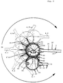
- FIG. 3 shows, enlarged in a horizontal sectional plane, the first wall element 2 and the second wall element 4, which is shown in a position parallel to the outside 24 of the first wall element 2.
- thin lines 4.1 to 4.6 indicate further positions of the second wall element, which can be pivoted through an overall angle 26 of 360 ° to the inside 28. The pivoting takes place here about a vertical, virtual axis of rotation 30, which is located in the center of a vertical profile 32 of the first wall element 2.
- the second wall element 4 also contains a vertical profile 34.
- the two wall elements 2, 4 also contain, in a known manner, plates 36, 38, in particular made of silicate glass, which are connected to the profiles 32, 34 on the vertical longitudinal edges in a manner not to be further explained here are.
- the wall elements are practically frameless, that is to say the plates 36, 38 are not enclosed by a closed frame made of profiles or profile rails.
- the two profiles 32, 34 which are assigned to one another and arranged adjacent to one another, are present, while the other edges of the plates 36, 38 are free of profiles.
- a fastening and / or compensation profile can be provided on the right vertical edge of the first wall element 2 for connection to the room wall, if necessary.
- a sealing profile made of transparent plastic or other sealing means, in particular of silicone is also provided between the room wall and the vertical longitudinal edge of the fixed wall element 2 as shown in the drawing.
- the first vertical profile 32 of the first wall element 2 has, in a particularly expedient manner, a cylindrical outer surface 40 coaxial with the axis of rotation 30. Further is In a gap between the two profiles 32, 34, a seal 42 is provided which bears at least on the outer surface 40 of the first profile 32. When pivoting the second wall element 4, the seal 42 is moved along the substantially cylindrical outer surface 40 of the profile 32 of the first wall element 2, so that a functionally reliable seal against splash water is ensured in every rotational angle position. There are no flexible sealing tapes or the like which are exposed to considerable movements when carrying out the relative movements between the two wall elements 2, 4 and which wear out very quickly in practice. Rather, the seal 42 is only designed to be elastically resilient in such a way that it lies sealingly against the outer surface 40 of the first profile 32 in every rotational angle position.
- the seal 42 has in principle an H-shaped cross section with a central web 44 and four legs 46 to 49, the legs 46, 47 shown above according to the drawing residing elastically resiliently on the outer surface 40.
- the seal 42 expediently consists of plastic, elastomer or rubber, the legs 46 to 49 being designed as lips and partially overlapping the outer surface of the associated profile. The choice of material and shape thus ensure that the ends of the lips or legs 46 to 49 abut against the associated outer surfaces of the profiles 32, 34 in a sufficiently resilient manner.
- the pivot bearings already mentioned are designed in such a way that a predetermined, comparatively small gap is present between the profiles 32, 34, in which the seal 42 is arranged, specifically in the embodiment shown here with the central web 44.
- the second profile 34 also has an essentially cylindrical outer surface 50 which, like the first profile 32, is not cylindrical in the connection area with the associated plate, but instead has fastening webs 52, 54 for the plate 38 there.
- the lower lips or legs 48, 49 of the basically H-shaped seal 42 in turn, resiliently rest with a predeterminable prestress. Since the lips or legs 46 to 49 are arranged practically coaxially to the associated outer surface of the respective profile 32, 34 over a predetermined angular range, a comparatively low elastic preload is sufficient and, even after long use, grinding marks or damage to the outer surfaces 40, 50 are thus reliably avoided .
- the seal 42 surrounds the outer surface 40 of the first profile 32 over a circumferential angle 56, which is preferably greater than 90 °.
- the circumferential angle 56 is also less than 160 ° and is preferably in the range between 110 ° to 140 °. Due to the circumferential angle in which the seal 42 encompasses the cylindrical outer surface 40 or 50, a functionally reliable seal in the manner of a labyrinth seal is ensured.
- the lips or legs 46 to 49 can thus rest practically loosely on the associated outer surfaces 40 and 50, so that damage to the outer surfaces 40, 50 provided with paint, varnish or the like is excluded even after a long period of use.
- the seal 42 is pivoted about the axis of rotation 30 only over an angle of 180 ° along the outer surface 40 of the first profile 2.
- the seal 42 is coupled, preferably via its central web 44, to a connecting body which is only moved by half the pivoting angle of the two wall elements 2, 4 when the wall elements 2, 4 are pivoted relative to one another. This advantageously ensures that the seal properly maintains the desired position in the gap between the two profiles 32, 34.
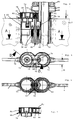
- FIG. 4 shows an enlarged view of the area of the upper pivot bearing 14 with which the first wall element 2 and the second wall element 4 are rotatably coupled to one another.
- the lower pivot bearing is designed accordingly and the explanations for the upper pivot bearing 14 apply accordingly.
- An end body 58, 60 is connected to the upper ends of the two profiles 32, 34, screws 62, 64 being provided for the fixed connection.
- the pivot bearing 14 also contains a common connecting body 66 which overlaps the two end bodies 58, 60 and is connected to them.
- bodies 68, 70 are also provided, which are fixedly connected with the respective end body 58, 60 by means of bolts 72, 74 with the interposition of the connecting body 66.
- the end bodies 58, 60, the common connecting body 66 and the bodies 68, 70 together with the bolts 72, 74 form a prefabricated assembly.
- This assembly or the upper pivot bearing 14 designed in this way can be fastened for assembly only by means of the screws 62, 64 at the upper end of the first and the second profile 32, 34 with extremely little assembly effort.
- the bodies 68, 70 have the associated end bodies 58, 60 corresponding contact surfaces and end surfaces, so that by means of the bolts 72, 74 a fixed, in particular non-rotatable coupling is ensured.
- the bodies 68, 70 each have a toothed ring 76, 78 on their outer surface, which are located within the connecting body 66 designed as a hollow body.
- the bodies 68, 70 with the toothed rings 76, 78 are rotatable with respect to the connecting body 66, the connecting body 66 itself being arranged axially secured in the swivel joint. Furthermore, the connecting body 66 is axially secured with respect to the wall elements 2, 4.
- the bodies 68, 70 are inserted into the cavity of the connecting body 66 from above, so that the toothed rings 76, 78 are not exposed, but are covered on the outside by the outer wall 80 of the connecting body 66.
- a cover 82 is also provided on the top of the connecting body 66, so that the bodies 68, 70 and / or the toothed rings 76, 78 are arranged in the largely closed interior of the connecting body in a manner protected from external influences.
- a tubular ceiling support 84 is partially inserted into the first profile 32, which is designed as a hollow profile.
- This ceiling support 84 can be telescopically pushed up out of the second profile 34 and fastened to the ceiling of the bathroom by means of a connecting element 86. After mounting the ceiling support 84, a cover cap 88 is pushed over the connecting element 86.
- the first fixed wall element 2 can be attached to a wall of the bathroom with a bracket, a bracket or the like.
- the gap 90 already mentioned is present between the two profiles 32.
- the middle web of the seal is arranged in this gap 90, which is not shown here for reasons of clarity.
- the seal extends over the entire vertical height of the gap 90 and expediently extends with its upper end to the connecting body 66 and is locked with respect to this.
- the lower end of the seal is locked in the connecting body of the lower pivot bearing.
- the connecting body is also pivoted synchronously by half the angle, and thus also the seal.
- FIG. 5 shows a top view of the shower partition without a connecting element and cover cap, the cover 82 of the connecting body 86 being clearly visible here.
- two small gears 92, 94 are also rotatably mounted, which both with one another and with the external teeth or Comb tooth rings 76, 78. Via these gears 92, 94 there is thus a gear connection between the profiles 32, 34 of the two wall elements in such a way that a synchronous rotary movement is achieved with simultaneous movement of the connecting body 66.
- the angle of rotation of the connecting body 66 is in each case only half as large as the mutual pivoting angle of the two wall elements 2, 4.
- the rotary movement of the seal is also always only half as large as that of the two wall elements.
- the small gear wheels 92, 94 rotatably mounted in the connecting body 66 are arranged at a predetermined distance 96 between the two vertical wall elements 2, 4. Due to the distance 96, the explained gap between the vertical profiles and / or the diameter of the ring gears 76, 78 can be kept small.
- FIG. 6 shows a section along the section line A according to FIG. 4, the central web 44 of the seal 42 being orthogonal to the common plane 98 of the two vertical wall elements 2, 4.
- the second wall element 4 is pivoted by 180 ° with respect to the first wall element 2, while the seal 42 and / or its central web 44 is only pivoted by 90 ° about the axis of rotation 30.
- FIG. 7 shows a section along section line B according to FIG. 5, the two gear wheels 92, 94 being clearly visible here.
- the gears 92, 94 are supported by means of short bearing journals in corresponding recesses in the connecting body 66 and in the cover 82.
- the gear 92 is in engagement with the ring gear 78 of the body 70 and correspondingly the other gear 94 with the ring gear of the first body, not shown here.
Landscapes
- Health & Medical Sciences (AREA)
- Public Health (AREA)
- Epidemiology (AREA)
- General Health & Medical Sciences (AREA)
- Bathtubs, Showers, And Their Attachments (AREA)
- Percussion Or Vibration Massage (AREA)
- Massaging Devices (AREA)
Applications Claiming Priority (2)
| Application Number | Priority Date | Filing Date | Title |
|---|---|---|---|
| DE29607376U | 1996-04-24 | ||
| DE29607376U DE29607376U1 (de) | 1996-04-24 | 1996-04-24 | Duschabtrennung |
Publications (2)
| Publication Number | Publication Date |
|---|---|
| EP0803222A2 true EP0803222A2 (fr) | 1997-10-29 |
| EP0803222A3 EP0803222A3 (fr) | 1998-03-18 |
Family
ID=8023012
Family Applications (1)
| Application Number | Title | Priority Date | Filing Date |
|---|---|---|---|
| EP97104253A Withdrawn EP0803222A3 (fr) | 1996-04-24 | 1997-03-13 | Paroi de douche |
Country Status (3)
| Country | Link |
|---|---|
| EP (1) | EP0803222A3 (fr) |
| DE (1) | DE29607376U1 (fr) |
| ZA (1) | ZA973398B (fr) |
Cited By (1)
| Publication number | Priority date | Publication date | Assignee | Title |
|---|---|---|---|---|
| EP0997095A3 (fr) * | 1998-10-30 | 2001-05-30 | Jeremy David Lenighan | Ecran de douche |
Families Citing this family (1)
| Publication number | Priority date | Publication date | Assignee | Title |
|---|---|---|---|---|
| WO2020168653A1 (fr) | 2019-02-21 | 2020-08-27 | 福建西河卫浴科技有限公司 | Paravent et cabine de douche |
Family Cites Families (9)
| Publication number | Priority date | Publication date | Assignee | Title |
|---|---|---|---|---|
| BE733576A (fr) * | 1969-05-23 | 1969-11-03 | ||
| CH659682A5 (de) * | 1983-04-05 | 1987-02-13 | Alu System Ag | Faltwand. |
| DE8701832U1 (de) * | 1986-05-23 | 1987-04-23 | Hallengren, Ulf, Onsala | Scharnierelement |
| CH674390A5 (fr) * | 1986-10-14 | 1990-05-31 | Lista Degersheim Ag | |
| DE3644543A1 (de) * | 1986-12-24 | 1988-07-14 | Kermi Gmbh | Faltwand |
| DE8714788U1 (de) * | 1987-02-18 | 1988-01-07 | Schulte Duschkabinenbau Gmbh & Co Kg, 5768 Sundern | Faltwand für Badewannen, Duschwannen o. dgl. |
| EP0450649A1 (fr) * | 1990-04-05 | 1991-10-09 | Hajimu Toma | Porte pliante |
| DE4215526C2 (de) * | 1991-05-13 | 1996-08-14 | Manuela Huber | Horizontal zweigeteilte Dusche mit Abtrennelement(en) und 360 GRD-Schwenkbereich insbesondere für pflegebedürftige Personen |
| DE9304050U1 (de) * | 1993-03-19 | 1994-07-21 | Hoesch Metall + Kunststoffwerk GmbH & Co, 52372 Kreuzau | Duschabtrennung |
-
1996
- 1996-04-24 DE DE29607376U patent/DE29607376U1/de not_active Expired - Lifetime
-
1997
- 1997-03-13 EP EP97104253A patent/EP0803222A3/fr not_active Withdrawn
- 1997-04-21 ZA ZA9703398A patent/ZA973398B/xx unknown
Cited By (1)
| Publication number | Priority date | Publication date | Assignee | Title |
|---|---|---|---|---|
| EP0997095A3 (fr) * | 1998-10-30 | 2001-05-30 | Jeremy David Lenighan | Ecran de douche |
Also Published As
| Publication number | Publication date |
|---|---|
| DE29607376U1 (de) | 1996-07-11 |
| ZA973398B (en) | 1997-11-20 |
| EP0803222A3 (fr) | 1998-03-18 |
Similar Documents
| Publication | Publication Date | Title |
|---|---|---|
| DE69214636T2 (de) | Gleitelementsystem | |
| DE3445642C2 (fr) | ||
| DE69303304T2 (de) | Dichtungsvorrichtung mit rohrförmigem Profilelement, insbesondere für Kraftfahrzeug | |
| DE2514941A1 (de) | Markise | |
| EP0562245A1 (fr) | Marquise | |
| DE69500766T2 (de) | Fliegengitter für ein fenster | |
| WO2008083714A1 (fr) | Filtre pour fluides | |
| DE69606793T2 (de) | Verbesserte Bewegungsvorrichtung zum Öffnen und Schliessen einer Kleiderschranktür | |
| DE3707795A1 (de) | Duschabtrennung | |
| DE4106235C1 (fr) | ||
| EP0803222A2 (fr) | Paroi de douche | |
| EP3581752B1 (fr) | Fenêtre | |
| DE3139330A1 (de) | Faltduschwand | |
| CH639458A5 (de) | Drehfluegeltuer fuer eine duschkabine. | |
| DE3340476A1 (de) | Fahrzeugfenster mit einer verschiebbaren fensterscheibe | |
| DE102018112434A1 (de) | Fenster | |
| DE2258311B1 (de) | Rolladen,insbesondere fuer Feuerloeschfahrzeuge | |
| DE69001043T2 (de) | Faltwand. | |
| EP3680438A1 (fr) | Profilé d'étanchéité pour un profilé de cadre et profilé de cadre | |
| DE3719829A1 (de) | Trennwandeinheit mit einzelnen rand an rand aneinandergefuegten plattenelementen | |
| DE8902207U1 (de) | Duschkabinen-Schiebetür | |
| DE29913356U1 (de) | Stirnwandabdichtung für Schwimmbadüberdachungen | |
| DE2201546A1 (de) | Tuerzarge mit in die zarge eingebauten tuerbaendern | |
| DE29724615U1 (de) | Duschabtrennung | |
| DE1878571U (de) | Schiebefluegelrahmen. |
Legal Events
| Date | Code | Title | Description |
|---|---|---|---|
| PUAI | Public reference made under article 153(3) epc to a published international application that has entered the european phase |
Free format text: ORIGINAL CODE: 0009012 |
|
| AK | Designated contracting states |
Kind code of ref document: A2 Designated state(s): AT CH DE ES FR GB IT LI |
|
| PUAL | Search report despatched |
Free format text: ORIGINAL CODE: 0009013 |
|
| AK | Designated contracting states |
Kind code of ref document: A3 Designated state(s): AT CH DE ES FR GB IT LI |
|
| STAA | Information on the status of an ep patent application or granted ep patent |
Free format text: STATUS: THE APPLICATION IS DEEMED TO BE WITHDRAWN |
|
| 18D | Application deemed to be withdrawn |
Effective date: 19980919 |