EP0802586B1 - Socle, spécialement pour tube fluorescent en forme de tige - Google Patents
Socle, spécialement pour tube fluorescent en forme de tige Download PDFInfo
- Publication number
- EP0802586B1 EP0802586B1 EP97105742A EP97105742A EP0802586B1 EP 0802586 B1 EP0802586 B1 EP 0802586B1 EP 97105742 A EP97105742 A EP 97105742A EP 97105742 A EP97105742 A EP 97105742A EP 0802586 B1 EP0802586 B1 EP 0802586B1
- Authority
- EP
- European Patent Office
- Prior art keywords
- socket
- contact
- socket body
- slot
- contact elements
- Prior art date
- Legal status (The legal status is an assumption and is not a legal conclusion. Google has not performed a legal analysis and makes no representation as to the accuracy of the status listed.)
- Expired - Lifetime
Links
Images


Classifications
-
- H—ELECTRICITY
- H01—ELECTRIC ELEMENTS
- H01R—ELECTRICALLY-CONDUCTIVE CONNECTIONS; STRUCTURAL ASSOCIATIONS OF A PLURALITY OF MUTUALLY-INSULATED ELECTRICAL CONNECTING ELEMENTS; COUPLING DEVICES; CURRENT COLLECTORS
- H01R33/00—Coupling devices specially adapted for supporting apparatus and having one part acting as a holder providing support and electrical connection via a counterpart which is structurally associated with the apparatus, e.g. lamp holders; Separate parts thereof
- H01R33/05—Two-pole devices
- H01R33/06—Two-pole devices with two current-carrying pins, blades or analogous contacts, having their axes parallel to each other
- H01R33/08—Two-pole devices with two current-carrying pins, blades or analogous contacts, having their axes parallel to each other for supporting tubular fluorescent lamp
Definitions
- the invention relates to a version, in particular for rod-shaped fluorescent tubes with two-pin base or for equipment with two contact pins.
- Sockets for fluorescent lamps or tubes that with a 2-pin base according to IEC G5 or G13 are provided, consistently in the form of a multi-part housing designed electrically, insulating Socket body.
- a guide slot accessible from the front trained for the contact pins in which a Insertion slot opens out to one end of the housing leads and it allows the contact pins in the guide slot introduce.
- Patent 3,654,587 described. While with these versions the housing each with a separated, clipped or welded Back wall is provided, which has a longitudinally slotted cylindrical pin that carries the circular Insertion slot on the other part of the housing inside limited, embodiments are also known in practice, where the housing is double-walled and on a narrow side by an insoluble one Cover is closed, which the contact springs in their Installation position holds and the insertion channels for the to the Has contact springs to be connected electrical conductor.
- the object of the invention is therefore a version especially for rod-shaped fluorescent tubes with Two-pin base or for two corresponding contact pins equipment (e.g. capacitors, plugs and the like), which is characterized by a simple, reliable construction distinguished and inexpensive can be produced.
- two corresponding contact pins equipment e.g. capacitors, plugs and the like
- Socket according to the invention characterized in that the Frame body slit-like Wells for the contact-proof reception of the contact elements has, in which the contact elements locked are and to the front and / or back of the socket body are essentially open.
- One-piece socket bodies are very simple Way of plastic, for example. Can be produced by injection molding. By dispensing with lids, caps or other additional parts, as in the known housing designs are required, there is also a very easy installation. You only need the two Contact springs in the intended and their shape adapted slot-like depressions used in which they are automatically held captive are. The dimensions of these slit-like depressions, i.e. in particular the slot depth and the slot width are chosen so that the contact springs, i.e. the contact element, in its respective recess after insertion is kept safe from touch without it additional measures would be required.
- the formation of the one-piece socket body with from one side and / or from the other side into the Sockets protruding from the socket body allow a very simple design of the injection mold and the other one free air circulation, and so is the danger a heat build-up, as with closed housings Occurs occasionally, avoided from the outset.
- the socket body channels and / or through openings can further improve heat dissipation in the socket body channels and / or through openings to enable and / or improve air circulation relief through the socket body be trained.
- the Guide slot from the front to the back of the socket body have continuous areas.
- the circular guide slot for the contact pins is delimited on the inside by a longitudinally slotted pin, one end of this can be in one piece on the socket body trained, web-like or arm-like carrier means sit, which in turn breaks through again, for example with continuous ones Channels can be formed.
- Locking in a secure manner can be particularly useful for Embodiments in which one in the annular Guide slot used rotating body waived is the socket body molded for the Have contact pins that protrude into the guide slot are arranged.
- such Locking means can also be provided on the contact elements, at least in the contact area with advantage a groove-like recess for receiving the contact pins exhibit.
- connection means of the contact means in each case contain an insulation displacement contact that is safe to touch in a slit-like recess in the socket body is received and has an insulation displacement slot, which in a longitudinal extension crossing the slot continuous and to one side along its length open cable reception channel.
- This line intake channel is in its adjoining the insulation displacement slot Areas dimensioned so that one next to the Insulation displacement slot cut cable end without additional measures, safe to touch in the channel is kept.
- the line receiving channel serves to guide the cable laying tool when making contact of the conductor, as for example in EP-A1-0573 791 is described.
- the Arrangement must be made such that the line receiving channels of the two contact elements with their planes of symmetry arranged at such an angle enclosing each other are that their openings in the extension of their The axis direction is essentially unobstructed. This arrangement also allows unhindered starting the contact point with the line laying tool, without that additional line diversions and thus movement steps of the line laying tool required would.
- the contact elements can - if necessary additionally - at least one plug contact each have the touch-proof on the socket body trained cable entry and / or receiving devices assigned. This makes it possible to work on the frame additional electrical equipment or cables to connect, like the other one with plug contacts Equipped socket also for automatic wiring systems Can be used where contacting at the individual contact points via plug connections, i.e. takes place in the so-called plug contact technology.
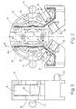
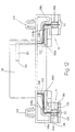
- FIG. 1-6 The version shown in Figures 1-6 has one made of an electrically insulating plastic, massive, essentially disc-shaped Socket body 1, whose substantially flat front is denoted by 2 and parallel to that at 3 indicated, also essentially flat back 3 runs.
- the socket body 1 is over a central angle of approx. 180 ° at 4 circular cylindrical on its circumference shaped; then there are two strip-like ones on it Extensions 5 formed, the flat bottom 6 in one common level.
- annular guide slot 7 is provided in an insertion slot starting from the peripheral region 4 8 opens, the plane of symmetry at right angles the plane containing the surfaces 6 runs.
- the circular one Guide slot 7 is on the inside limited by a coaxial, circular cylindrical pin 9, which by means of the insertion slot 8 aligned and the same width as this one Longitudinal slot 10 is divided into two.
- the pin 9 is on the in Figure 1 facing away from the viewer to a strip-shaped Support part 11 formed on a thin wall (Fig.2), which is made in one piece from the material of the socket body 1 molded, extending across a guide slot 7 outer limiting circular opening 12 in the Socket body 1 extends from the front to goes through the web-shaped support member 11. That symmetrical to the insertion slot 8 arranged support member 11 is with to the rear 3 through channels 13 and with from the Back 3 outgoing, ( Figure 2) approximately part-circular Wells 14 formed, which extend almost to the front 2 extend such that the pin 9 as thin-walled Hollow body is formed.
- each of the two contact springs 15 in designed essentially L-shaped or C-shaped, with their contact area 16 with the recess 18 by a relaxed Condition essentially straight leg 19 formed at an angle of e.g. 120 ° a contact means in the form of an insulation displacement slot 20 containing, second leg. 21 connects.
- Each of the contact springs 15 is in one shape essentially adapted slot-like depression 26 of the socket body 1, which is to the rear 3 of the socket body 1 opens.
- the slit-like Indentation 26 runs through the associated one Extension 5 and extends to the guide slot 7, into which it enters at 27 ( Figure 2).
- the recess 26 is located on the opposite side 26a away, the slot-like recess part 26a from Bottom of a circular cylindrical opening 29, which is also to the rear 3 of the socket body 1 opens and closed Is used for testing purposes.
- the slot-like depression assigned in each case 26, 26a inserted contact spring 15 is in the area the front 2 of the socket body 1 by thin Wall parts 30, 31 and on the back 3 of the socket body 1 by a mounting lug 32 from falling out hindered.
- the two diametrically opposite one another Mounting lugs 32 of the two contact springs 15 protrude into the guide slot 7 and cover at the same time this from the back 3 from touch safe.
- the width and depth of the slit-like depressions 26, 26 a are chosen so that the used therein Contact springs 15 without additional measures, such as own covers and the like, safe to touch are kept.
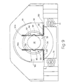
- the contact springs 15 are in the disc-shaped Socket body 1 from the back chamber-like Wells 33, 34 are formed, which extend up to extend a thin bottom wall almost to the front 2 or go through to it; are also through the socket body through channels 35, 36 provided the together with the openings 13 and the chamber-like Wells 33, 34 for a large one, for heat exchange with the area available and a ensure good air circulation through the socket body 1.
- the guide slot 7 is next to it the web-like support part 11 from the front to the back formed continuously, with the slot width on the back is dimensioned so that a perfect Protection against contact for the contact spring used 15 remains.
- each of the two extensions 5 is in the range of second leg 21 of the associated contact spring 15 the corresponding part of the slot-like depression 26 crossing line receiving channel 38 formed, the at 39 indicated plane of symmetry in the middle through the insulation displacement slot 20 of the contact spring 15 extends.
- Everyone who Line receiving channels 38 is essentially in cross section U-shaped (see Figure 7) and of parallel or slightly sloping side walls 40 and a flat bottom wall 41 limited.
- To the Side walls 40 of the back 3 over his The length of the open cable receiving channel 38 are lead-in slopes 42 available for an electrical line.
- On both sides of the leg 21 of the contact spring 15 has each line receiving channel 38 a cross-sectional constriction 43 (FIG. 2) on, which is dimensioned such that one in the cable entry channel 38 inserted electrical line with your Isolation at the side of the cross-sectional constriction 43 limiting ribs can be clamped.
- the dimensions (depth, width and length) of one greater width than the electrical cable to be inserted having the line receiving channel 38 are dimensioned in such a way that one in the line receiving channel 38 next to the Insulation displacement slot 20 cut line end, without further measures, in the corresponding section of the Line receiving channel 38 is kept safe from contact.
- the line receiving channels 38 are for interaction with the cable laying tool of an automatic wiring system suitable, as in EP-A1-0573 791 is described.
- the two line receiving channels 38 arranged at an angle to one another, with their planes of symmetry 39 an angle of enclose more than 90 ° (approx. 115 °).
- the socket body 1 is still open opposite sides of two locking pins or Split pins 44 molded, which allow the frame with which Back 3 of the socket body 1 facing a support, to attach to this.
- the socket body 1 molded locking elements 45 which in Areas of the projections 5 are also used to fix the frame; they can if necessary also used to connect additional parts become.
- the one-piece socket body only recesses has that of the front and / or back starting in the immediate vicinity of the extend opposite side or as a continuous Channels are formed, there is a very simple Design of the for the manufacture of the socket body 1 required injection mold. At the same time it is for the production of necessary plastic to a minimum reduced without sacrificing strength or stability of the socket body having a honeycomb structure 1 would be affected.
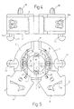
- each contact spring 15 with its legs 21, 25 in the slot-like depression 26 in the longitudinal direction held immovably and at the free end of the first leg 19 is longitudinally displaceable in the slot region 26a is guided, the first contact spring leg 19 when transferring to that shown in Figure 5
- Use position of the respective contact pin 46 um a line about 27 ( Figure 2, 5) elastically outwards bent, the free end from the slit-like Recess area 26a is partially withdrawn. This creates a relatively large radial pressure force exerted on the contact pins 46.
- At the radial after outward movement of the contact spring leg 19 this enters under the assigned mounting lug 32, with the result that the contact spring against axial pushing out secured form-fitting from the socket body 1 is.
- Locking recesses can be arranged, one of which is in figure 5 is indicated by dash-dotted lines at 47 and for recording the contact pins 46 set up in the operating position are. This way, an additional one The fluorescent lamp is secured in the socket become.
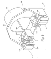
- the socket is set up by means of the locking pins 44 on the inner wall of a light box or the like to be attached is one in Figures 8 to 12 Embodiment illustrated in which the socket body 100 inside a pot or cup-shaped, from Plastic existing housing 50 in the axial direction is integrally molded in an outstanding manner.
- Such a version mounting housings containing are typically found in louvre luminaires and the like, using it arrives, the inner dimensions of the light box in Longitudinal direction of the fluorescent tubes as completely as possible to exploit and therefore one of the versions just outside of the light box. This purpose is For example, explained in DE-U1 29 50 54 51.
- the disc-shaped socket body 100 is on it facing the opening edge 101 of the add-on housing 50 Side with an annular guide slot 70 for the contact pins of the fluorescent lamp to be inserted educated.
- the insertion slot 8 of the embodiment according to Figures 1 to 6 is omitted, as is the Guide slot 70 internally limiting, circular cylindrical Pin 90 executed without the longitudinal slot 10 of Figure 1 is.
- the In this respect, relationships are basically similar to the embodiment described with reference to Figures 1 to 7 and are therefore not explained again.
- connection devices 51 formed for electrical conductors (Fig. 8, 12) in which contact means in the form of Insulation displacement contacts of the contact springs 150 are safe to touch are included. These connection devices have each have an element 52 designed as an insulation displacement terminal on that a line receiving channel 380 U-shaped cross-sectional shape contains the same as the cable entry channel 38 of Figures 2, 6 designed and therefore is not further explained.
- the line receiving channel 380 crosses an L-shaped leg 230c of the associated contact spring 150 in which an insulation displacement slot 200 is formed is.
- the insulation displacement slot 200 is aligned with the Level of symmetry of the assigned line receiving channel 380, which in turn is near the insulation displacement slot 200 again with the cross-sectional constrictions already explained 430 is executed.
- the two line receiving channels 380 are parallel to the containing the opening edge 101 of the attachment housing 50 Level aligned, being in the axial direction or can also be offset from each other in height.
- the part of the leg emerging from the attachment housing 50 230b is like the adjoining leg 230c touch-proof for each of the two contact springs 150 in a slit-like opening open to the top Recess 260c, which corresponds to the shape of the Contact spring leg is adjusted accordingly.
- plug contact points provided in the contact spring legs 230b allow it via assigned cable entry openings 54, additional lines from the outside or Connect equipment to the contact springs 150 (Fig. 9, 12).
Landscapes
- Connecting Device With Holders (AREA)
- Fastening Of Light Sources Or Lamp Holders (AREA)
Claims (19)
- Douille en particulier pour des lampes à fluorescence en forme de tube à culot à deux broches ou des éléments fonctionnels à deux broches, comprenant un corps de douille monobloc, électriquement isolant, dans lequel est aménagée une rainure de guidage pour les broches de contact, accessible à partir d'une face avant du corps de douille, et au moins deux éléments de contact élastiques qui sont logés dans le corps de douille en étant protégés contre les contacts accidentels et comportent chacun une zone de contact pour les broches de contact qui fait saillie dans la rainure de guidage,
caractérisée par le fait que
le corps de douille (1; 100) comporte des cavités (26; 26a; 260; 260a) en forme de rainures destinées à recevoir de manière protégée contre les contacts accidentels les éléments de contact, dans lesquelles les éléments de contact (15; 150) sont encliquetés ou fixés et qui sont essentiellement ouvertes en direction de la face avant et/ou de la face arrière (2; 3) du corps de douille. - Douille selon la revendication 1, caractérisée par le fait que des canaux/cavités (14; 90a) et/ou des ouvertures débouchantes (13; 90c) sont aménagées dans le corps de douille (1; 100) afin de permettre et/ou d'améliorer la circulation de l'air dans le corps de douille (1; 100).
- Douille selon la revendication 1 ou 2, caractérisée par le fait que la fente de guidage (7; 70) présente des zones traversantes qui s'étendent de la face à la face arrière (2; 3) du corps de douille (1).
- Douille selon la revendication 3, caractérisée par le fait que la rainure de guidage en forme d'anneau circulaire (7) est limitée intérieurement par un bossage (9) pourvu d'une fente longitudinale qui est lié par une extrémité à des moyens de support (11) en forme de barrettes ou de bras moulés d'une pièce avec le corps de douille (1).
- Douille selon la revendication 4, caractérisée par le fait que les moyens de support (11) comportent des canaux débouchants (13).
- Douille selon une des revendications précédentes, caractérisée par le fait que le corps de douille (1) comporte des moyens d'encliquetage (47) moulés d'une pièce pour les broches de contact (46), qui font saillie dans la rainure de guidage (7).
- Douille selon une des revendications précédentes, caractérisée par le fait que les éléments de contact, dans la zone de contact ( 16; 160) comportent chacun au moins une cavité (18; 180) en forme de gouttière pour recevoir les broches de contact (46).
- Douille selon une des revendications précédentes, caractérisée par le fait que des moyens de fixation (32) sont prévus sur le corps de douille (1) afin de fixer axialement les éléments de contact (15), qui sont disposés au moins dans la région de la rainure de guidage (7).
- Douille selon une des revendications précédentes, caractérisée par le fait que le corps de douille (1) comporte des moyens de fixation (44; 45) qui sont moulés d'une pièce avec ledit corps.
- Douille selon une des revendications précédentes, caractérisée par le fait que le corps de douille (1; 100) comporte des dispositifs de connexion pour des lignes électriques qui sont moulés d'une pièce avec le corps et contiennent chacun des moyens de contact (20; 200) associés à au moins un élément de contact (15; 150).
- Douille selon la revendication 10, caractérisée par le fait que les dispositifs de connexion comprennent comme moyens de contact (15) chacun un contact autodénudant (20; 21) qui est monté de manière protégée contre les contacts accidentels dans une cavité (26) en forme de fente du corps de douille (1) et comporte une fente de dénudage-serrage (20) qui est située dans un canal de réception de ligne (38) sécant avec la fente, débouchant dans la direction longitudinale et est sur un côté sur toute sa longueur.
- Douille selon la revendication 11, caractérisée par le fait que les canaux de réception de ligne (38) des deux éléments de contact (15) sont disposés de telle sorte que leurs plans de symétrie forment entre eux un angle tel que les ouvertures des canaux, dans le prolongement de leur axe, soient essentiellement dégagées.
- Douille selon une des revendications précédentes, caractérisée par le fait que les éléments de contact (15; 150) comportent chacun au moins un contact enfichable (24; 240), auquel sont associés sur le corps de douille ou sur un élément (51) lié à celui-ci, des dispositifs d'introduction et/ou de réception de ligne protégés contre les contacts accidentels.
- Douille selon une des revendications précédentes, caractérisée par le fait que les éléments de contact sont des ressorts de contact (15) essentiellement en forme de L ou de C, qui portent sur une aile (19) la zone de contact (16) et sur une autre aile (21) des moyens de contact électriques pour au moins un conducteur électrique à connecter, et par le fait que les ressorts de contact (15), au niveau de leur partie située à l'extérieur de la fente d'introduction (20), sont montés essentiellement sur toute leur longueur dans une cavité en forme de fente (26;26a) du corps de douille (1).
- Douille selon une des revendications précédentes, caractérisée par le fait qu'elle est disposée dans un boítier de montage (50) en forme de cuvette et est fixée fermement au fond de celui-ci.
- Douille selon la revendication 15, caractérisée par le fait que le corps de douille (100) est moulé d'une pièce avec le fond du boítier de montage (50).
- Douille selon la revendication 15 ou 16, caractérisée par le fait que les éléments de contact (150) sortent du boítier de montage (50) et sont montés de manière protégée contre les contacts accidentels dans des parties (260b; 260c) du boítier de montage (50).
- Douille selon la revendication 17, caractérisée par le fait que le boítier de montage (50) en forme de cuvette comporte dans la région du bord (110) de son ouverture des dispositifs de connexion (51) pour des conducteurs électriques, dans lesquels des moyens de contact (200; 250c) des éléments de connexion (150) sont montés en étant protégés contre les contacts accidentels.
- Douille selon la revendication 18, caractérisée par le fait que les moyens de connexion comportent des contacts autodénudants dont les fentes de dénudage-serrage (200) sont orientées avec leur axe essentiellement parallèle au plan contenant le bord de l'ouverture (110) du boítier de montage (50).
Applications Claiming Priority (2)
| Application Number | Priority Date | Filing Date | Title |
|---|---|---|---|
| DE19615373A DE19615373C2 (de) | 1996-04-19 | 1996-04-19 | Fassung, insbesondere für stabförmige Leuchtstoffröhren |
| DE19615373 | 1996-04-19 |
Publications (3)
| Publication Number | Publication Date |
|---|---|
| EP0802586A2 EP0802586A2 (fr) | 1997-10-22 |
| EP0802586A3 EP0802586A3 (fr) | 1998-09-02 |
| EP0802586B1 true EP0802586B1 (fr) | 2000-05-17 |
Family
ID=7791671
Family Applications (1)
| Application Number | Title | Priority Date | Filing Date |
|---|---|---|---|
| EP97105742A Expired - Lifetime EP0802586B1 (fr) | 1996-04-19 | 1997-04-08 | Socle, spécialement pour tube fluorescent en forme de tige |
Country Status (4)
| Country | Link |
|---|---|
| EP (1) | EP0802586B1 (fr) |
| AT (1) | ATE193165T1 (fr) |
| DE (2) | DE19615373C2 (fr) |
| ES (1) | ES2146436T3 (fr) |
Families Citing this family (5)
| Publication number | Priority date | Publication date | Assignee | Title |
|---|---|---|---|---|
| DE19738461C2 (de) * | 1997-09-03 | 1999-09-23 | Vossloh Schwabe Gmbh | Federnd gelagerte Lampenfassung |
| FR2806542B1 (fr) * | 2000-03-17 | 2004-03-12 | Sarl C E I T Entpr S | Douille pour lampe du type alimente par des paires de broches de contact, notamment pour lampe fluorescente du type dit a fenetre, et support de lampe comprenant de telles douilles |
| AUPQ906100A0 (en) * | 2000-07-28 | 2000-08-24 | Giannopoulos, Peter | A tube adaptor to allow existing fluorescent light fittings to be converted to utilise new energy efficient light tubes |
| AU2001276181B2 (en) * | 2000-07-28 | 2006-01-19 | Peter Giannopoulos | Fluorescent light tube adaptor |
| US8767996B1 (en) | 2014-01-06 | 2014-07-01 | Alpine Electronics of Silicon Valley, Inc. | Methods and devices for reproducing audio signals with a haptic apparatus on acoustic headphones |
Family Cites Families (9)
| Publication number | Priority date | Publication date | Assignee | Title |
|---|---|---|---|---|
| BE505269A (fr) * | ||||
| US2241065A (en) * | 1939-12-08 | 1941-05-06 | Gen Electric | Lamp socket |
| US2297738A (en) * | 1942-01-28 | 1942-10-06 | Bryant Electric Co | Lamp holder |
| US3654587A (en) * | 1970-01-15 | 1972-04-04 | Westinghouse Electric Corp | Fluorescent lampholder or the like |
| US3975073A (en) * | 1971-12-02 | 1976-08-17 | Westinghouse Electric Corporation | Fluorescent lampholder with means for circuit interruption |
| DE2559818C3 (de) * | 1975-04-15 | 1983-01-05 | Brökelmann, Jaeger & Busse GmbH & Co, 5760 Arnsberg | Fassung für Leuchtstofflampen und Verfahren zu ihrer Herstellung |
| DE4218741C2 (de) * | 1992-06-06 | 1994-10-20 | Vossloh Schwabe Gmbh | Verfahren zum Verdrahten von Anschlußstellen elektrischer Geräte oder Baugruppenelemente |
| DE4312776C2 (de) * | 1993-04-20 | 1995-08-31 | Vossloh Schwabe Gmbh | Fassung für elektrische Betriebsmittel |
| DE29505451U1 (de) * | 1995-03-31 | 1995-06-01 | Broekelmann Jaeger & Busse | Anbaugehäuse für eine Lampenfassung in Leuchtengehäusen |
-
1996
- 1996-04-19 DE DE19615373A patent/DE19615373C2/de not_active Expired - Fee Related
-
1997
- 1997-04-08 DE DE59701691T patent/DE59701691D1/de not_active Expired - Fee Related
- 1997-04-08 EP EP97105742A patent/EP0802586B1/fr not_active Expired - Lifetime
- 1997-04-08 ES ES97105742T patent/ES2146436T3/es not_active Expired - Lifetime
- 1997-04-08 AT AT97105742T patent/ATE193165T1/de not_active IP Right Cessation
Also Published As
| Publication number | Publication date |
|---|---|
| EP0802586A2 (fr) | 1997-10-22 |
| DE19615373A1 (de) | 1997-10-23 |
| DE59701691D1 (de) | 2000-06-21 |
| ATE193165T1 (de) | 2000-06-15 |
| EP0802586A3 (fr) | 1998-09-02 |
| ES2146436T3 (es) | 2000-08-01 |
| DE19615373C2 (de) | 1998-07-02 |
Similar Documents
| Publication | Publication Date | Title |
|---|---|---|
| EP0678932B1 (fr) | Borne de raccordement et de connexion électrique | |
| DE3830134C2 (de) | Einstückige elektrische Steckbuchse und damit ausgerüstete Gehäusebaugruppe | |
| EP0212330B1 (fr) | Borne de jonction ou serre-fil pour appareils électriques | |
| EP2654147B1 (fr) | Adaptateur de barre collectrice | |
| DE3628211C2 (fr) | ||
| DE4128928C2 (de) | Elektrische Verbindungseinheit für eine Hochdruck-Entladungslampe | |
| DE19857087C2 (de) | Elektrischer Verbinder für Kraftfahrzeugleuchte | |
| DE4432509A1 (de) | Elektro-Installationsgerät, insbesondere für Kabelkanäle | |
| DE4312781C2 (de) | Anschlußelement für wenigstens ein elektrisches Betriebsmittel | |
| EP0802586B1 (fr) | Socle, spécialement pour tube fluorescent en forme de tige | |
| DE19521735C2 (de) | Steckelement zum Befestigen und Anschließen einer Lampe | |
| EP0444478A1 (fr) | Porte-contact pour prise de courant ou connecteur pour le raccordement de remorques de véhicules | |
| EP0221201A1 (fr) | Boîtier pour circuits électriques et électroniques | |
| EP0352347A1 (fr) | Connecteur électrique | |
| EP0082469A2 (fr) | Boîtier pour loger les composants électriques nécessaires pour l'activation d'une bobine d'un aimant d'une valve hydraulique ou similaire | |
| DE3841006C2 (de) | Steckdose für eine Steckverbindung für den elektrischen Anschluß von Kraftfahrzeuganhängern | |
| EP0401723A1 (fr) | Prise de courant et connecteur pour réaliser le raccordement électrique de remorques de véhicule | |
| AT504268B1 (de) | Sicherungssockel | |
| DE102017119806B4 (de) | Kabelanschlussgehäuse und Verfahren zum zugentlasteten Anbringen eines elektrischen Kabels an einem Kabelanschlussgehäuse | |
| DE3542349C2 (fr) | ||
| DE10100605B4 (de) | Elektrische Beleuchtungsvorrichtung mit einer punktförmigen Lichtquelle | |
| EP0833547B1 (fr) | Dispositif de signalisation lumineux | |
| EP1257009B1 (fr) | Soulagement de traction pour connecteur enfichable à contact plat unique et connecteur enfichable avec celui-ci | |
| EP1467448B1 (fr) | Adaptateur de connecteur, notament pour connexion de lampes | |
| DE4026124A1 (de) | Anschlussdose fuer elektrische leitungen |
Legal Events
| Date | Code | Title | Description |
|---|---|---|---|
| PUAI | Public reference made under article 153(3) epc to a published international application that has entered the european phase |
Free format text: ORIGINAL CODE: 0009012 |
|
| AK | Designated contracting states |
Kind code of ref document: A2 Designated state(s): AT BE DE ES FR GB IT NL |
|
| PUAL | Search report despatched |
Free format text: ORIGINAL CODE: 0009013 |
|
| AK | Designated contracting states |
Kind code of ref document: A3 Designated state(s): AT BE DE ES FR GB IT NL |
|
| 17P | Request for examination filed |
Effective date: 19981013 |
|
| GRAG | Despatch of communication of intention to grant |
Free format text: ORIGINAL CODE: EPIDOS AGRA |
|
| 17Q | First examination report despatched |
Effective date: 19990506 |
|
| GRAG | Despatch of communication of intention to grant |
Free format text: ORIGINAL CODE: EPIDOS AGRA |
|
| GRAH | Despatch of communication of intention to grant a patent |
Free format text: ORIGINAL CODE: EPIDOS IGRA |
|
| GRAH | Despatch of communication of intention to grant a patent |
Free format text: ORIGINAL CODE: EPIDOS IGRA |
|
| GRAA | (expected) grant |
Free format text: ORIGINAL CODE: 0009210 |
|
| AK | Designated contracting states |
Kind code of ref document: B1 Designated state(s): AT BE DE ES FR GB IT NL |
|
| REF | Corresponds to: |
Ref document number: 193165 Country of ref document: AT Date of ref document: 20000615 Kind code of ref document: T |
|
| ET | Fr: translation filed | ||
| REF | Corresponds to: |
Ref document number: 59701691 Country of ref document: DE Date of ref document: 20000621 |
|
| ITF | It: translation for a ep patent filed |
Owner name: JACOBACCI & PERANI S.P.A. |
|
| RAP2 | Party data changed (patent owner data changed or rights of a patent transferred) |
Owner name: VOSSLOH SCHWABE GMBH |
|
| REG | Reference to a national code |
Ref country code: ES Ref legal event code: FG2A Ref document number: 2146436 Country of ref document: ES Kind code of ref document: T3 |
|
| GBT | Gb: translation of ep patent filed (gb section 77(6)(a)/1977) |
Effective date: 20000728 |
|
| NLT2 | Nl: modifications (of names), taken from the european patent patent bulletin |
Owner name: VOSSLOH SCHWABE GMBH |
|
| PLBE | No opposition filed within time limit |
Free format text: ORIGINAL CODE: 0009261 |
|
| STAA | Information on the status of an ep patent application or granted ep patent |
Free format text: STATUS: NO OPPOSITION FILED WITHIN TIME LIMIT |
|
| 26N | No opposition filed | ||
| REG | Reference to a national code |
Ref country code: GB Ref legal event code: IF02 |
|
| PGFP | Annual fee paid to national office [announced via postgrant information from national office to epo] |
Ref country code: NL Payment date: 20030325 Year of fee payment: 7 |
|
| PGFP | Annual fee paid to national office [announced via postgrant information from national office to epo] |
Ref country code: GB Payment date: 20030326 Year of fee payment: 7 |
|
| PGFP | Annual fee paid to national office [announced via postgrant information from national office to epo] |
Ref country code: AT Payment date: 20030403 Year of fee payment: 7 |
|
| PGFP | Annual fee paid to national office [announced via postgrant information from national office to epo] |
Ref country code: FR Payment date: 20030408 Year of fee payment: 7 |
|
| PGFP | Annual fee paid to national office [announced via postgrant information from national office to epo] |
Ref country code: ES Payment date: 20030422 Year of fee payment: 7 |
|
| PGFP | Annual fee paid to national office [announced via postgrant information from national office to epo] |
Ref country code: BE Payment date: 20030423 Year of fee payment: 7 |
|
| PGFP | Annual fee paid to national office [announced via postgrant information from national office to epo] |
Ref country code: DE Payment date: 20030430 Year of fee payment: 7 |
|
| NLT1 | Nl: modifications of names registered in virtue of documents presented to the patent office pursuant to art. 16 a, paragraph 1 |
Owner name: VOSSLOH-SCHWABE DEUTSCHLAND GMBH |
|
| PG25 | Lapsed in a contracting state [announced via postgrant information from national office to epo] |
Ref country code: GB Free format text: LAPSE BECAUSE OF NON-PAYMENT OF DUE FEES Effective date: 20040408 Ref country code: AT Free format text: LAPSE BECAUSE OF NON-PAYMENT OF DUE FEES Effective date: 20040408 |
|
| PG25 | Lapsed in a contracting state [announced via postgrant information from national office to epo] |
Ref country code: ES Free format text: LAPSE BECAUSE OF NON-PAYMENT OF DUE FEES Effective date: 20040410 |
|
| PG25 | Lapsed in a contracting state [announced via postgrant information from national office to epo] |
Ref country code: BE Free format text: LAPSE BECAUSE OF NON-PAYMENT OF DUE FEES Effective date: 20040430 |
|
| BERE | Be: lapsed |
Owner name: *VOSSLOH-SCHWABE DEUTSCHLAND G.M.B.H. Effective date: 20040430 |
|
| PG25 | Lapsed in a contracting state [announced via postgrant information from national office to epo] |
Ref country code: NL Free format text: LAPSE BECAUSE OF NON-PAYMENT OF DUE FEES Effective date: 20041101 |
|
| PG25 | Lapsed in a contracting state [announced via postgrant information from national office to epo] |
Ref country code: DE Free format text: LAPSE BECAUSE OF NON-PAYMENT OF DUE FEES Effective date: 20041103 |
|
| GBPC | Gb: european patent ceased through non-payment of renewal fee |
Effective date: 20040408 |
|
| PG25 | Lapsed in a contracting state [announced via postgrant information from national office to epo] |
Ref country code: FR Free format text: LAPSE BECAUSE OF NON-PAYMENT OF DUE FEES Effective date: 20041231 |
|
| NLV4 | Nl: lapsed or anulled due to non-payment of the annual fee |
Effective date: 20041101 |
|
| REG | Reference to a national code |
Ref country code: FR Ref legal event code: ST |
|
| PG25 | Lapsed in a contracting state [announced via postgrant information from national office to epo] |
Ref country code: IT Free format text: LAPSE BECAUSE OF NON-PAYMENT OF DUE FEES;WARNING: LAPSES OF ITALIAN PATENTS WITH EFFECTIVE DATE BEFORE 2007 MAY HAVE OCCURRED AT ANY TIME BEFORE 2007. THE CORRECT EFFECTIVE DATE MAY BE DIFFERENT FROM THE ONE RECORDED. Effective date: 20050408 |
|
| REG | Reference to a national code |
Ref country code: ES Ref legal event code: FD2A Effective date: 20040410 |