EP0802586B1 - Socket, especially for rod-shaped fluorescent tubes - Google Patents
Socket, especially for rod-shaped fluorescent tubes Download PDFInfo
- Publication number
- EP0802586B1 EP0802586B1 EP97105742A EP97105742A EP0802586B1 EP 0802586 B1 EP0802586 B1 EP 0802586B1 EP 97105742 A EP97105742 A EP 97105742A EP 97105742 A EP97105742 A EP 97105742A EP 0802586 B1 EP0802586 B1 EP 0802586B1
- Authority
- EP
- European Patent Office
- Prior art keywords
- socket
- contact
- socket body
- slot
- contact elements
- Prior art date
- Legal status (The legal status is an assumption and is not a legal conclusion. Google has not performed a legal analysis and makes no representation as to the accuracy of the status listed.)
- Expired - Lifetime
Links
Images


Classifications
-
- H—ELECTRICITY
- H01—ELECTRIC ELEMENTS
- H01R—ELECTRICALLY-CONDUCTIVE CONNECTIONS; STRUCTURAL ASSOCIATIONS OF A PLURALITY OF MUTUALLY-INSULATED ELECTRICAL CONNECTING ELEMENTS; COUPLING DEVICES; CURRENT COLLECTORS
- H01R33/00—Coupling devices specially adapted for supporting apparatus and having one part acting as a holder providing support and electrical connection via a counterpart which is structurally associated with the apparatus, e.g. lamp holders; Separate parts thereof
- H01R33/05—Two-pole devices
- H01R33/06—Two-pole devices with two current-carrying pins, blades or analogous contacts, having their axes parallel to each other
- H01R33/08—Two-pole devices with two current-carrying pins, blades or analogous contacts, having their axes parallel to each other for supporting tubular fluorescent lamp
Landscapes
- Connecting Device With Holders (AREA)
- Fastening Of Light Sources Or Lamp Holders (AREA)
Abstract
Description
Die Erfindung betrifft eine Fassung, insbesondere für stabförmige Leuchtstoffröhren mit Zweistiftsockel oder für zwei Kontaktstifte aufweisende Betriebsmittel.The invention relates to a version, in particular for rod-shaped fluorescent tubes with two-pin base or for equipment with two contact pins.
Derartige Fassungen sind aus US-A-2 241 065 bereits bekannt.Such sockets are already known from US-A-2 241 065.
Fassungen für Leuchtstofflampen- oder röhren, die mit einem 2-Stiftsockel nach IEC G5 oder G13 (DIN 49653) versehen sind, weisen durchweg einen in Gestalt eines mehrteiligen Gehäuses ausgebildeten elektrisch, isolierenden Fassungskörper auf. In der Vorderwand dieses Gehäuses ist ein von der Vorderseite her zugänglicher Führungsschlitz für die Kontaktstifte ausgebildet, in dem ein Einführschlitz mündet, der zu einer Stirnseite des Gehäuses führt und es erlaubt die Kontaktstifte in den Führungsschlitz einzuführen. In dem Gehäuse sind wenigstens zwei federnde Kontaktelemente berührungssicher untergebracht, von denen jedes einen in den Führungsschlitz ragenden Kontaktbereich für die Kontaktstifte aufweist und die jeweils mit Kontaktmitteln in Gestalt von Steckkontakten oder Schneidklemmkontakten ausgestattet sind, welche den Anschluß von außen kommender elektrischer Leiter erlauben. Beispiele für solche bekannte Fassungen sind in der EP-A2-0 621 661 und in der US-PS 3 654 587 beschrieben. Während bei diesen Fassungen das Gehäuse jeweils mit einer abgetrennten, aufgeklipsten oder aufgeschweißten Rückwand versehen ist, die einen längsgeschlitzten zylindrischen Zapfen trägt, der den kreisringförmigen Einführschlitz am anderen Gehäuseteil innen begrenzt, sind in der Praxis auch Ausführungsformen bekannt, bei denen das Gehäuse doppelwandig ausgebildet und auf einer Schmalseite durch einen unlösbar eingesetzten Deckel verschlossen ist, der die Kontaktfedern in ihrer Einbaulage hält und die Einführkanäle für die an die Kontaktfedern anzuschliessenden elektrischen Leiter aufweist.Sockets for fluorescent lamps or tubes that with a 2-pin base according to IEC G5 or G13 (DIN 49653) are provided, consistently in the form of a multi-part housing designed electrically, insulating Socket body. In the front wall of this case is a guide slot accessible from the front trained for the contact pins in which a Insertion slot opens out to one end of the housing leads and it allows the contact pins in the guide slot introduce. At least there are in the housing two resilient contact elements housed in a touch-safe manner, each one in the guide slot projecting contact area for the contact pins and each with contact means in the form of plug contacts or insulation displacement contacts, which is the connection of external electrical Allow ladder. Examples of such known versions are in EP-A2-0 621 661 and in U.S. Patent 3,654,587 described. While with these versions the housing each with a separated, clipped or welded Back wall is provided, which has a longitudinally slotted cylindrical pin that carries the circular Insertion slot on the other part of the housing inside limited, embodiments are also known in practice, where the housing is double-walled and on a narrow side by an insoluble one Cover is closed, which the contact springs in their Installation position holds and the insertion channels for the to the Has contact springs to be connected electrical conductor.
Wie die beiden vorerwähnten Druckschriften zeigen, ist es bekannt, bei solchen Fassungen in den kreisringförmigen Führungsschlitz für die Kontaktstifte einen aus Isoliermaterial bestehenden Drehkörper drehbar einzusetzen oder wahlweise auf einen solchen Drehkörper zu verzichten. In jedem Falle ist aber Vorsorge getroffen, daß die in den Führungsschlitz ragenden Kontaktbereiche der Kontaktelemente berührungssicher verwahrt sind. Fassungen mit kreisringförmig gestaltetem Einführschlitz für die Kontaktstifte sind in der Praxis weit verbreitet; es gibt aber auch Fassungen mit geradem oder Y-förmigem Einführschlitz, um lediglich zwei Beispiele für eine andere gebräuchliche Schlitzgestaltung zu erwähnen.As the two publications mentioned above show it is known in such versions in the circular Guide slot for the contact pins one out Insulating material to use existing rotating body rotatable or optionally to dispense with such a rotating body. In any case, however, precautions are taken to ensure that those in the Guide slot projecting contact areas of the contact elements are kept safe from touch. Sockets with a circular shape designed insertion slot for the contact pins are widespread in practice; but there is also sockets with straight or Y-shaped insertion slots, just two examples of another common one Slit design to mention.
Die Verwendung eines zwei- oder mehrteiligen Fassungskörpers in Gestalt eines Gehäuses bedingt einen verhältnismäßig hohen Montageaufwand, zu dem bei einigen doppelwandigen Gehäusekonstruktionen noch hinzutritt, daß sie für ihre Herstellung aus Kunststoff komplizierte Spritzgußformen notwendig machen. Außerdem erlauben die geschlossenen Gehäuse erfahrungsgemäß keine wirksame Abfuhr der über den Sockel der Leuchtstofflampe im Betrieb in sie eingeleiteten Wärme, mit der Folge, daß verhältnismäßig hohe Betriebstemperaturen auftreten können. Diese können, wie die praktische Erfahrung gezeigt hat, unter Umständen sogar dazu führen, daß der in dem Führungsschlitz gelagerte Drehkörper mit der ihn umgebenden Gehäusewandung verklebt wird, so daß die Leuchtstofflampe nicht mehr einfach aus der Fassung gelöst werden kann. Um dies zu verhindern, müssen verhältnismäßig hochwertige Kunststoffe eingesetzt werden, die die erforderliche erhöhte Wärmefestigkeit aufweisen.The use of a two-part or multi-part socket body in the form of a housing requires one relatively high assembly costs, to which some double-walled housing constructions still added that complicated for their manufacture from plastic Make injection molds necessary. They also allow experience has shown that closed housings are not effective Removal via the base of the fluorescent lamp during operation heat introduced into it, with the result that proportionate high operating temperatures can occur. This can, as practical experience has shown, under Circumstances may even result in the in the guide slot mounted rotating body with the surrounding housing wall is glued so that the fluorescent lamp is not can be easily removed from the socket. To do this to prevent needing relatively high quality plastics be used, which increases the required Have heat resistance.
Aufgabe der Erfindung ist es deshalb, eine Fassung, insbesondere für stabförmige Leuchtstoffröhren mit Zweistiftsockel oder für zwei entsprechende Kontaktstifte aufweisende Betriebsmittel (bspw. Kondensatoren, Stecker und dergleichen) zu schaffen, die sich durch einen einfachen, betriebssicheren Aufbau auszeichnet und preisgünstig herstellbar ist.The object of the invention is therefore a version especially for rod-shaped fluorescent tubes with Two-pin base or for two corresponding contact pins equipment (e.g. capacitors, plugs and the like), which is characterized by a simple, reliable construction distinguished and inexpensive can be produced.
Zur Lösung dieser Aufgabe ist die eingangs genannte Fassung erfindungsgemäß dadurch gekennzeichnet, daß der Fassungskörper schlitzartige Vertiefungen zur berührungssicheren Aufnahme der Kontaktelemente aufweist, in denen die Kontaktelemente verrastet sind und die zur Vorder- und/oder Rückseite des Fassungskörpers hin im wesentlichen offen sind.To solve this problem, the above is Socket according to the invention characterized in that the Frame body slit-like Wells for the contact-proof reception of the contact elements has, in which the contact elements locked are and to the front and / or back of the socket body are essentially open.
Einteilige Fassungskörper sind in sehr einfacher Weise aus Kunststoff, bspw. im Spritzgußverfahren herstellbar. Durch den Verzicht auf Deckel, Kappen oder andere Zusatzteile, wie sie bei den bekannten Gehäusekonstruktionen erforderlich sind, ergibt sich auch eine sehr einfache Montage. Es brauchen nämlich lediglich die beiden Kontaktfedern in die dafür vorgesehenen und ihrer Gestalt angepassten schlitzartigen Vertiefungen eingesetzt zu werden, in denen sie automatisch unverlierbar gehalten sind. Die Abmessungen dieser schlitzartigen Vertiefungen, d.h. insbesondere die Schlitztiefe und die Schlitzweite sind so gewählt, daß die Kontaktfedern, d,h. das Kontaktelement, in seiner jeweiligen Vertiefung nach dem Einsetzen berührungssicher verwahrt ist, ohne daß es dazu noch zusätzlicher Maßnahmen bedürfte.One-piece socket bodies are very simple Way of plastic, for example. Can be produced by injection molding. By dispensing with lids, caps or other additional parts, as in the known housing designs are required, there is also a very easy installation. You only need the two Contact springs in the intended and their shape adapted slot-like depressions used in which they are automatically held captive are. The dimensions of these slit-like depressions, i.e. in particular the slot depth and the slot width are chosen so that the contact springs, i.e. the contact element, in its respective recess after insertion is kept safe from touch without it additional measures would be required.
Die Ausbildung des einteiligen Fassungskörpers mit von der einen und/oder von der anderen Seite her in den Fassungskörper ragenden Vertiefungen erlaubt eine sehr einfache Gestaltung der Spritzgußform und zum anderen eine freie Luftzirkulation, und auf diese Weise ist die Gefahr eines Wärmestaus, wie sie bei geschlossenen Gehäusen gelegentlich auftritt, von vornherein vermieden. Zusätzlich können zur weiteren Verbesserung der Wärmeabfuhr in dem Fassungskörper Kanäle und/oder durchgehende Öffnungen zur Ermöglichung und/oder Verbesserung einer Luftzirkulation durch den Fassungskörper hindurch Erleichterung ausgebildet sein. Aus ähnlichen Erwägungen kann auch der Führungsschlitz von der Vorder- zur Rückseite des Fassungskörpers durchgehende Bereiche aufweisen. Wenn der kreisringförmige Führungsschlitz für die Kontaktstifte innen durch einen längsgeschlitzten Zapfen begrenzt ist, kann dieser einerends auf einstückig an dem Fassungskörper ausgebildeten, steg- oder armartigen Trägermitteln sitzen, die ihrerseits auch wieder durchbrochen, bspw. mit durchgehenden Kanälen ausgebildet sein können.The formation of the one-piece socket body with from one side and / or from the other side into the Sockets protruding from the socket body allow a very simple design of the injection mold and the other one free air circulation, and so is the danger a heat build-up, as with closed housings Occurs occasionally, avoided from the outset. In addition can further improve heat dissipation in the socket body channels and / or through openings to enable and / or improve air circulation relief through the socket body be trained. For similar considerations, the Guide slot from the front to the back of the socket body have continuous areas. If the circular guide slot for the contact pins is delimited on the inside by a longitudinally slotted pin, one end of this can be in one piece on the socket body trained, web-like or arm-like carrier means sit, which in turn breaks through again, for example with continuous ones Channels can be formed.
Um die Leuchtstofflampe in der Betriebsstellung bestriebssicher zu verriegeln, kann insbesondere bei Ausführungsformen, bei denen auf einen in den kreisringförmigen Führungsschlitz eingesetzten Drehkörper verzichtet ist der Fassungskörper angeformte Rastmittel für die Kontaktstifte aufweisen, die in den Führungsschlitz ragend angeordnet sind. Alternativ oder zusätzlich können solche Rastmittel auch an den Kontaktelementen vorgesehen sein, die mit Vorteil in dem Kontaktbereich jeweils wenigstens eine rinnenartige Vertiefung zur Aufnahme der Kontaktstifte aufweisen. Around the fluorescent lamp in the operating position Locking in a secure manner can be particularly useful for Embodiments in which one in the annular Guide slot used rotating body waived is the socket body molded for the Have contact pins that protrude into the guide slot are arranged. Alternatively or additionally, such Locking means can also be provided on the contact elements, at least in the contact area with advantage a groove-like recess for receiving the contact pins exhibit.
Um sicherzustellen, daß die Kontaktelemente, insbesondere bei einem Einschieben oder Herausziehen der Kontaktstifte aus dem Führungsschlitz, nicht mitgenommen oder durch andere Einflüsse in Achsrichtung der eingesetzten Kontaktstifte verstellt werden, ist es zweckmäßig, daß an dem Fassungskörper Halterungsmittel zur axialen Fixierung der Kontaktelemente ausgebildet sind, die in Bereiche, wenigstens des Führungsschlitzes angeordnet sind.To ensure that the contact elements, in particular when inserting or removing the Contact pins from the guide slot, not taken away or by other influences in the axial direction of the used Contact pins are adjusted, it is appropriate that on the socket body holding means for axial fixation of the contact elements which are formed in areas at least the guide slot are arranged.
Eine weitere Vereinfachung lässt sich dadurch erzielen, daß der Fassungskörper einstückig angeformte Anschlußeinrichtungen für elektrische Leitungen aufweist, in denen jeweils wenigstens einem der Kontaktelemente zugeordnete Kontaktmittel enthalten sind. Damit entfällt die Notwendigkeit für zusätzliche, gegebenenfalls getrennt herzustellende Anschlußeinrichtungen, bspw. Klemmkörper und dergleichen. Insbesondere bei Verwendung der Fassung in automatischen Verdrahtungssystemen, wie sie z.B. bei der weitgehend automatisierten Herstellung von Leuchten neuerdings zunehmend gebräuchlich sind, ist es zweckmäßig, wenn die Anschlußeinrichtungen der Kontaktmittel jeweils einen Schneidklemmkontakt enthalten, der berührungssicher in einer schlitzartigen Vertiefung des Fassungsköpers aufgenommen ist und einen Schneidklemmschlitz aufweist, welcher in einem den Schlitz querenden, in Längserstrekkung durchgehenden und zu einer Seite hin über seine Länge offenen Leitungsaufnahmekanal liegt. Dieser Leitungsaufnahmekanal ist in seinen an den Schneidklemmschlitz anschließenden Bereichen so dimensioniert, daß ein neben dem Schneidklemmschlitz abgeschnittenes Leitungsende ohne zusätzliche Maßnahmen, in dem Kanal berührungssicher verwahrt ist. Gleichzeitig dient der Leitungsaufnahmekanal zur Führung des Leitungsverlegewerkzeugs bei der Kontaktierung des Leiters, wie dies bspw. in der EP-A1-0573 791 beschrieben ist. Um eine automatische Durchverdrahtung der Fassung zu ermöglichen oder zu erleichtern, kann die Anordnung derart getroffen sein, daß die Leitungsaufnahmekanäle der beiden Kontaktelemente mit ihren Symmetrieebenen einen Winkel miteinander einschließend derart angeordnet sind, daß ihre Öffnungen in der Verlängerung ihrer Achsrichtung im wesentlichen unbehindert frei liegen. Diese Anordnung erlaubt auch ein unbehindertes Anfahren der Kontaktstelle mit dem Leitungsverlegewerkzeug, ohne daß dazu zusätzliche Leitungsumlenkungen und damit Bewegungsschritte des Leitungsverlegungswerkzeuges erforderlich würden.A further simplification can be achieved that the socket body integrally molded connection devices for electrical lines, in which each assigned at least one of the contact elements Contact agents are included. This eliminates the Need for additional, if necessary separately Connection devices to be manufactured, for example and the same. Especially when using the frame in automatic wiring systems, e.g. at the largely automated production of lights are becoming increasingly common recently, it is expedient if the connection means of the contact means in each case contain an insulation displacement contact that is safe to touch in a slit-like recess in the socket body is received and has an insulation displacement slot, which in a longitudinal extension crossing the slot continuous and to one side along its length open cable reception channel. This line intake channel is in its adjoining the insulation displacement slot Areas dimensioned so that one next to the Insulation displacement slot cut cable end without additional measures, safe to touch in the channel is kept. At the same time, the line receiving channel serves to guide the cable laying tool when making contact of the conductor, as for example in EP-A1-0573 791 is described. For automatic through wiring of the To enable or facilitate the version, the Arrangement must be made such that the line receiving channels of the two contact elements with their planes of symmetry arranged at such an angle enclosing each other are that their openings in the extension of their The axis direction is essentially unobstructed. This arrangement also allows unhindered starting the contact point with the line laying tool, without that additional line diversions and thus movement steps of the line laying tool required would.
Die Kontaktelemente können im übrigen - gegebenenfalls zusätzlich - jeweils wenigstens einen Steckkontakt aufweisen, dem an dem Fassungskörper berührungssicher ausgebildete Leitungseinführ- und/oder Aufnahmeeinrichtungen zugeordnet sind. Damit ist es möglich, an der Fassung noch zusätzliche elektrische Betriebsmittel oder Leitungen anzuschliessen, wie andererseits eine mit Steckkontakten ausgerüstete Fassung auch bei automatischen Verdrahtungssystemen Verwendung finden kann, bei denen die Kontaktierung an den einzelnen Kontaktstellen über Steckverbindungen, d.h. in der sogenannten Steckkontaktechnik erfolgt.The contact elements can - if necessary additionally - at least one plug contact each have the touch-proof on the socket body trained cable entry and / or receiving devices assigned. This makes it possible to work on the frame additional electrical equipment or cables to connect, like the other one with plug contacts Equipped socket also for automatic wiring systems Can be used where contacting at the individual contact points via plug connections, i.e. takes place in the so-called plug contact technology.
Weitere Ausgestaltungen der Erfindung sind Gegenstand von Unteransprüchen.Further refinements of the invention are the subject of subclaims.
In der Zeichnung sind Ausführungsbeispiele des Gegenstandes
der Erfindung dargestellt. Es zeigen:
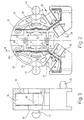
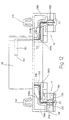
Die in den Figuren 1 - 6 dargestellte Fassung weist
einen aus einem elektrisch isolierenden Kunststoff hergestellten,
massiven, im wesentlichen scheibenförmigen
Fassungskörper 1 auf, dessen im wesentlichen ebene Vorderseite
mit 2 bezeichnet ist und parallel zu der bei 3
angedeuteten, ebenfalls im wesentlichen ebenen Rückseite 3
verläuft. Der Fassungskörper 1 ist über einen Zentriwinkel
von ca. 180° bei 4 an seinem Umfang kreiszylindrisch
geformt; daran anschließend sind an ihm zwei leistenartige
Fortsätze 5 angeformt, deren ebene Unterseite 6 in einer
gemeinsamen Ebene liegt.The version shown in Figures 1-6 has
one made of an electrically insulating plastic,
massive, essentially disc-shaped
Socket body 1, whose substantially flat front
is denoted by 2 and parallel to that at 3
indicated, also essentially flat back 3
runs. The socket body 1 is over a central angle
of approx. 180 ° at 4 circular cylindrical on its circumference
shaped; then there are two strip-like ones on it
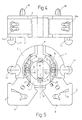
Konzentrisch zu dem kreiszylindrischen Bereich 4 ist
in dem Fassungskörper 1, von der Vorderseite 2 ausgehend,
ein kreisringförmiger Führungsschlitz 7 vorgesehen, in
den, von dem Umfangsbereich 4 ausgehend, ein Einführschlitz
8 mündet, dessen Symmetrieebene rechtwinklig zu
der die Flächen 6 enthaltenden Ebene verläuft. Der kreisringförmige
Führungsschlitz 7 ist auf seiner Innenseite
durch einen koaxialen, kreiszylindrischen Zapfen 9 begrenzt,
welcher durch einen mit dem Einführschlitz 8
fluchtenden und die gleiche Breite wie dieser aufweisenden
Längsschlitz 10 zweigeteilt ist. Der Zapfen 9 ist auf der
in Figur 1 dem Betrachter abgewandten Seite an ein leistenförmiges
Trägerteil 11 geringer Wandstärke angeformt
(Fig.2), das einstückig aus dem Material des Fassungskörpers
1 ausgeformt, sich quer über eine den Führungsschlitz
7 außen begrenzende kreisrunde Öffnung 12 in dem
Fassungskörper 1 erstreckt, die von der Vorderseite bis zu
dem stegförmigen Trägerteil 11 durchgeht. Das symmetrisch
zu dem Einführschlitz 8 angeordnete Trägerteil 11 ist mit
zur Rückseite 3 durchgehenden Kanälen 13 und mit von der
Rückseite 3 ausgehenden, (Figur 2) etwa teilkreisförmigen
Vertiefungen 14 ausgebildet, welche sich fast bis zur Vorderseite
2 erstrecken, derart, daß der Zapfen 9 als dünnwandiger
Hohlkörper ausgebildet ist. Is concentric to the circular cylindrical region 4
in the socket body 1, starting from the
In dem Fassungskörper 1 sind beidseitig des Zapfens 9
zwei Kontaktelemente bildende Kontaktfedern 15 untergebracht,
die jeweils mit einem Kontaktbereich 16 nach Art
von Sekanten den Führungsschlitz 7 beidseitig des Zapfens
9 durchqueren und mittig in dem Kontaktbereich 16 jeweils
mit einer querverlaufenden, rinnenartigen Vertiefung 18
ausgebildet sind. Wie insbesondere aus den Figuren 2 und 6
zu entnehmen ist, ist jede der beiden Kontaktfedern 15 im
wesentlichen L- oder C-förmig gestaltet, wobei ihr Kontaktbereich
16 mit der Vertiefung 18 durch einen im entspannten
Zustand im wesentlichen geraden Schenkel 19
gebildet ist, an den sich unter einem Winkel von z.B.120°
ein Kontaktmittel in Gestalt eines Schneidklemmschlitzes
20 enthaltender, zweiter Schenkel.21 anschliesst. Mit dem
zweiten Schenkel 21 ist einstückig ein etwa rechtwinklig
zu dem ersten Schenkel 15 verlaufender dritter Schenkel 23
verbunden, in dem zwei Steckkontakte 24 vorgesehen sind,
die durch U-förmig ausgeschnittene Lappen gebildet sind.
Auf den dritten Schenkel 23 schliesslich folgt ein rechtwinklig
abgewinkelter vierter Schenkel 25, der etwa parallel
zu dem ersten Schenkel 19 verläuft. Die Leitungseinführkanäle
für die Steckkontakte sind mit 24a bezeichnet
(Figur 4).In the socket body 1 are the
Jede der Kontaktfedern 15 ist in einer ihrer Gestalt
im wesentlichen angepassten, schlitzartigen Vertiefung 26
des Fassungskörpers 1 untergebracht, die sich zur Rückseite
3 des Fassungskörpers 1 hin öffnet. Die schlitzartige
Vertiefung 26 verläuft jeweils durch den zugeordneten
Fortsatz 5 und erstreckt sich bis zu dem Führungsschlitz
7, in den sie bei 27 jeweils eintritt (Figur 2). Auf der
in Figur 2 der Eintrittsstelle 27 in den Führungsschlitz 7
gegenüberliegenden Seite setzt sich die Vertiefung 26 bei
26a fort, wobei der schlitzartige Vertiefungsteil 26a vom
Boden einer kreiszylindrischen Öffnung 29, die sich ebenfalls
zur Rückseite 3 des Fassungskörpers 1 öffnet und zu
Prüfzwecken dient, ausgeht. Each of the contact springs 15 is in one shape
essentially adapted slot-
Die in die jeweils zugeordnete schlitzartige Vertiefung
26, 26a eingesetzte Kontaktfeder 15 ist im Bereiche
der Vorderseite 2 des Fassungskörpers 1 durch dünne
Wandungsteile 30, 31 und auf der Rückseite 3 des Fassungskörpers
1 durch eine Halterungsnase 32 am Herausfallen
gehindert. Die beiden diametral aneinander gegenüberliegenden
Halterungsnasen 32 der beiden Kontaktfedern 15
ragen in den Führungsschlitz 7 und decken gleichzeitig
diesen von der Rückseite 3 her berührungssicher ab.The slot-like depression assigned in each
Die Breite und die Tiefe der schlitzartigen Vertiefungen
26, 26 a sind so gewählt, daß die darin eingesetzten
Kontaktfedern 15, ohne zusätzliche Maßnahmen, wie
eigene Abdeckungen und dergleichen, berührungssicher
verwahrt sind.The width and depth of the slit-
Außer den schlitzartigen Vertiefungen 26, 26a zur
Aufnahme der Kontaktfedern 15, sind in dem scheibenförmigen
Fassungskörper 1 von der Rückseite ausgehende kammerartige
Vertiefungen 33, 34 ausgebildet, die sich bis auf
eine dünne Bodenwand fast bis zur Vorderseite 2 erstrecken
oder zu dieser durchgehen; außerdem sind durch den Fassungskörper
durchgehende Kanäle 35, 36 vorgesehen, die
gemeinsam mit den Durchbrüchen 13 und den kammerartigen
Vertiefungen 33, 34 für eine große, für den Wärmeaustausch
mit der Umgebung zur Verfügung stehende Fläche und eine
gute Luftzirkulation durch den Fassungskörper 1 sorgen.
Aus dem gleichen Grunde ist der Führungsschlitz 7 neben
dem stegartigen Trägerteil 11 von der Vorder- zur Rückseite
durchgehend ausgebildet, wobei die Schlitzweite auf
der Rückseite so bemessen ist, daß eine einwandfreie
Berührungssicherheit für die jeweils eingesetzte Kontaktfeder
15 erhalten bleibt.In addition to the slot-
In jedem der beiden Fortsätze 5 ist im Bereiche des
zweiten Schenkels 21 der zugeordneten Kontaktfeder 15 ein
den entsprechenden Teil der schlitzartigen Vertiefung 26
querender Leitungsaufnahmekanal 38 ausgebildet, dessen bei
39 angedeutete Symmetrieebene mittig durch den Schneidklemmschlitz
20 der Kontaktfeder 15 verläuft. Jeder der
Leitungsaufnahmekanäle 38 ist im Querschnitt im wesentlichen
U-förmig gestaltet (vergleiche Figur 7) und von
parallelen oder leicht zum Boden hin geneigten Seitenwänden
40 und einer ebenen Bodenwand 41 begrenzt. An den
Seitenwänden 40 des zu der Rückseite 3 hin über seine
Länge offenen Leitungsaufnahmekanals 38 sind Einführschrägen
42 für eine elektrische Leitung vorhanden. Beidseitig
des Schenkels 21 der Kontaktfeder 15 weist jeder Leitungsaufnahmekanal
38 eine Querschnittsverengung 43 (Fig. 2)
auf, die derart bemessen ist, daß eine in den Leitungseinführungskanal
38 eingelegte elektrische Leitung mit ihrer
Isolation an den die Querschnittsverengung 43 seitlich
begrenzenden Rippen festklemmbar ist.In each of the two
Die Abmessungen (Tiefe, Weite und Länge) des eine
größere Weite als die einzulegende elektrische Leitung
aufweisenden Leitungsaufnahmekanals 38 sind derart bemessen,
daß ein in dem Leitungsaufnahmekanal 38 neben dem
Schneidklemmschlitz 20 abgeschnittenes Leitungsende, ohne
weitere Maßnahmen, in dem entsprechenden Abschnitt des
Leitungsaufnahmekanals 38 berührungssicher verwahrt ist.The dimensions (depth, width and length) of one
greater width than the electrical cable to be inserted
having the
Die Leitungsaufnahmekanäle 38 sind zum Zusammenwirken
mit dem Leitungsverlegewerkzeug eines automatischen Verdrahtungssystems
geeignet, wie es in der EP-A1-0573 791
beschrieben ist. Wie aus Figur 2 zu entnehmen, sind die
beiden Leitungsaufnahmekanäle 38 winklig zueinander angeordnet,
wobei ihre Symmetrieebenen 39 einen Winkel von
mehr als 90° (ca. 115°) einschliessen. Durch diese Anordnung
wird erreicht, daß jeder der beiden Leitungsaufnahmekanäle
38 in der Verlängerung seiner Symmetrieebene 39
völlig unbehindert ist, so daß eine eingelegte Leitung
frei zugeführt werden kann und insbesondere ein Leitungsverlegewerkzeug
bei der Kontaktierung die von dem Schneidklemmschlitz
20 gebildete Kontaktierungsstelle frei anfahren
und von dieser frei wegfahren kann. The
An dem Fassungskörper 1 sind schliesslich noch auf
einander gegenüberliegenden Seiten zwei Raststifte oder
Splinte 44 angeformt, die es erlauben die Fassung, mit der
Rückseite 3 des Fassungskörpers 1 zu einem Träger weisend,
an diesem zu befestigen. Im Bereiche der Vorderseite 2 an
dem Fassungskörper 1 angeformte Rastelemente 45, die im
Bereiche der Vorsprünge 5 vorgesehen sind, dienen ebenfalls
zur Fixierung der Fassung; sie können erforderlichenfalls
auch zum Anschluß von Zusatzteilen verwendet
werden.Finally, the socket body 1 is still open
opposite sides of two locking pins or
Dadurch daß der einstückige Fassungskörper nur Vertiefungen aufweist, die von der Vorder- und/oder Rückseite ausgehend sich jeweils bis in die unmittelbare Nähe der gegenüberliegenden Seite erstrecken oder als durchgehende Kanäle ausgebildet sind, ergibt sich eine sehr einfache Gestaltung der für die Herstellung des Fassungskörpers 1 erforderlichen Spritzgussform. Gleichzeitig ist der für die Herstellung erforderliche Kunststoff auf ein Minimum reduziert, ohne daß dadurch die Festigkeit oder Stabilität des einen wabenförmigen Aufbau aufweisenden Fassungskörpers 1 beeinträchtigt wäre.Because the one-piece socket body only recesses has that of the front and / or back starting in the immediate vicinity of the extend opposite side or as a continuous Channels are formed, there is a very simple Design of the for the manufacture of the socket body 1 required injection mold. At the same time it is for the production of necessary plastic to a minimum reduced without sacrificing strength or stability of the socket body having a honeycomb structure 1 would be affected.
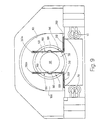
Bei der Benutzung werden die beiden Kontaktstifte der
in die Fassung einzusetzenden Leuchtstofflampe in der bei
solchen Fassungen gebräuchlichen Weise zunächst durch den
Einführschlitz 8 und den mit diesen fluchtenden Schlitz 10
(Figur 1) in Vertikalrichtung in den Führungsschlitz 7
eingeführt. Anschliessend wird die Leuchtstofflampe um
ihre Achse um 90° gedreht, bis die beiden in Figur 5 bei
46 angedeuteten Kontaktstifte die horizontale Gebrauchslage
einnehmen, in der sie drehfest elastisch verriegelt
sind. Bei dieser Verdrehung der Leuchtstofflampe schleifen
die beiden Kontaktstifte 46 über eine beträchtliche Länge
des Kontaktbereichs 16 des ersten Schenkels 19 der beiden
Kontaktfedern 15 bis sie in die rinnenförmigen Vertiefungen
18 finden, in denen sie lagefest lösbar verrastet
sind. Da jede Kontaktfeder 15 mit ihren Schenkeln 21, 25
in der schlitzartigen Vertiefung 26 in Längsrichtung
unverschieblich gehaltert und an dem freien Ende des
ersten Schenkels 19 in dem Schlitzbereich 26a längsverschieblich
geführt ist, wird der erste Kontaktfederschenkel
19 beim Überführen in die in Figur 5 dargestellte
Gebrauchsstellung von dem jeweiligen Kontaktstift 46 um
eine Linie etwa bei 27 (Figur 2, 5) elastisch nach außen
gebogen, wobei das freie Ende aus dem schlitzartigen
Vertiefungsbereich 26a teilweise zurückgezogen wird.
Dadurch wird eine verhältnismäßig große radiale Druckkraft
auf die Kontaktstifte 46 ausgeübt. Bei der radial nach
außen gerichteten Bewegung des Kontaktfederschenkels 19
tritt dieser unter die zugeordnete Halterungsnase 32 ein,
mit der Folge, daß die Kontaktfeder gegen axiales Herausschieben
aus dem Fassungskörper 1 formschlüssig gesichert
ist.When using the two contact pins
in the socket to be used in the fluorescent lamp
such versions, initially by the
Alternativ oder zusätzlich könnten in Bereiche der
Berandung der Öffnung 12 an dem Fassungskörper 1 auch
Rastvertiefungen angeordnet sein, von denen eine in Figur
5 bei 47 strichpunktiert angedeutet ist und die zur Aufnahme
der Kontaktstifte 46 in der Betriebsstellung eingerichtet
sind. Auf diese Weise kann noch eine zusätzliche
Sicherung der Leuchtstofflampe in der Fassung erzielt
werden.Alternatively or additionally, could be in areas of
Edging of the
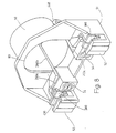
Während die vorstehend beschriebene Ausführungsform
der Fassung dazu eingerichtet ist, mittels der Raststifte
44 an der Innenwand eines Leuchtenkastens oder dergleichen
befestigt zu werden, ist in den Figuren 8 bis 12 eine
Ausführungsform veranschaulicht, bei der der Fassungskörper
100 im Inneren eines topf- oder becherförmigen, aus
Kunststoff bestehenden Anbaugehäuses 50 in Axialrichtung
vorragend einstückig angeformt ist. Solche, eine Fassung
enthaltende Anbaugehäuse finden typischerweise bei Rasterleuchten
und dergleichen Verwendung, bei denen es darauf
ankommt, die Innenabmessungen des Leuchtenkastens in
Längsrichtung der Leuchtröhren möglichst vollständig
auszunutzen und deshalb eine der Fassungen etwas außerhalb
des Leuchtenkastens zu verlegen. Dieser Einsatzzweck ist
bspw. in dem DE-U1 29 50 54 51 erläutert.During the embodiment described above
the socket is set up by means of the locking pins
44 on the inner wall of a light box or the like
to be attached is one in Figures 8 to 12
Embodiment illustrated in which the
Der scheibenförmige Fassungskörper 100 ist auf seiner
der Öffnungsberandung 101 des Anbaugehäuses 50 zugewandten
Seite mit einem kreisringförmigen Führungsschlitz 70 für
die Kontaktstifte der einzusteckenden Leuchtstofflampe
ausgebildet. Der Einführschlitz 8 der Ausführungsform,
nach den Figuren 1 bis 6 ist weggelassen, wie auch der den
Führungsschlitz 70 innen begrenzende, kreiszylindrische
Zapfen 90 ohne den Längsschlitz 10 nach Figur 1 ausgeführt
ist. Die den Führungsschlitz 70 sekantenartig beidseitig
des Zapfens 90 durchquerenden Kontaktfedern 150 weisen
einen sich durch den Führungsschlitz 70 erstreckenden
Kontaktbereich 160 auf, in dem eine rillenförmige Vertiefung
180 ausgebildet ist. Beide Kontaktfedern 150 sind
mit ihren den Kontaktbereich 160 tragenden Schenkeln 190
und den daran anschliessenden, abgewinkelten Schenkeln 210
in schlitzartigen Vertiefungen 260, 260a in dem Fassungskörper
100 bzw. in dem Boden des Anbaugehäuses 50, d.h. in
dem Fassungskörper 100 berührungssicher aufgenommen. Die
Verhältnisse sind insoweit grundsätzlich ähnlich wie bei
der anhand der Figuren 1 bis 7 geschilderten Ausführungsform
und werden deshalb nicht nochmal erläutert.The disc-shaped
Im Bereich seiner einander gegenüberliegenden Seitenwandungen
sind an dem Anbaugehäuse 50 zwei bis zur Öffnungsberandung
101 führende, durchgehende und im Querschnitt,
rechteckige Kanäle oder (im Behälterinneren)
schlitzartige Vertiefungen 260 b (Figur 8, 11) ausgebildet,
durch die die beiden Kontaktfedern 150 mit sich
jeweils an ihre Schenkeln 210 anschliessenden Schenkeln
230 berührungssicher nach außen geführt sind. Im Bereiche
seiner Öffnungsberandung 101 sind an das Anbaugehäuse 50
Anschlußeinrichtungen 51 für elektrische Leiter angeformt
(Fig. 8, 12), in denen Kontaktmittel in Gestalt von
Schneidklemmkontakten der Kontaktfedern 150 berührungssicher
enthalten sind. Diese Anschlußeinrichtungen weisen
jeweils ein als Schneidklemme ausgebildetes Element 52
auf, das einen Leitungsaufnahmekanal 380 U-förmiger Querschnittsgestalt
enthält, der gleich wie der Leitungseinführungskanal
38 der Figuren 2, 6 gestaltet und deshalb
nicht weiter erläutert ist. Den Leitungsaufnahmekanal 380
quert ein L-förmiger Schenkel 230c der zugeordneten Kontaktfeder
150 in dem ein Schneidklemmschlitz 200 ausgebildet
ist. Der Schneidklemmschlitz 200 fluchtet mit der
Symmetrieebene des zugeordneten Leitungsaufnahmekanals
380, der seinerseits in der Nähe des Schneidklemmschlitzes
200 wiederum mit den bereits erläuterten Querschnittsverengungen
430 ausgeführt ist. Mit ihren Symmetrieebenen 390
sind die beiden Leitungsaufnahmekanäle 380 parallel zu der
die Öffnungsberandung 101 des Anbaugehäuses 50 enthaltenden
Ebene ausgerichtet, wobei sie in Achsrichtung oder
auch der Höhe nach gegeneinander versetzt sein können. Der
aus dem Anbaugehäuse 50 austretende Teil des Schenkels
230b, ist ebenso wie der sich daran anschliessende Schenkel
230c bei jeder der beiden Kontaktfedern 150 berührungssicher
in einer zur Oberseite hin offenen schlitzartigen
Vertiefung 260c, aufgenommen, die der Gestalt der
Kontaktfederschenkel entsprechend angepasst ist. Bei 240
in den Kontaktfederschenkeln 230b vorgesehene Steckkontaktstellen,
erlauben es über zugeordnete Leitungseinführöffnungen
54, von außen her zusätzliche Leitungen oder
Betriebsmittel an die Kontaktfedern 150 anzuschliessen
(Fig. 9, 12).In the area of its opposite side walls
are on the
Zur Befestigung des Anbaugehäuses an der Wand des
Leuchtenkastens dienen neben dem Anbaugehäuse an die
Anschlußeinrichtungen 51 rückseitig angeformte Befestigungskrallen
440.To attach the extension housing to the wall of the
Luminaire boxes serve next to the add-on
Schliesslich ist aus der Ansicht von hinten (Figur
11) des Anbaugehäuses zu entnehmen, daß dessen Boden im
Bereiche des Fassungskörpers 100 mit Teilen des Fassungsköpers
100 und dessen Zapfens 90 entsprechenden topfartigen
Vertiefungen 90a, 90b und Durchbrüchen 90c versehen
ist, die für eine gute Wärmeabfuhr aus dem Anbaugehäuse 50
und für eine wirksame Luftzirkulation sorgen.Finally, from the rear view (figure
11) of the attachment housing that the bottom in
Areas of the
Claims (19)
- Socket, especially for rod-shaped fluorescent tubes with a two-pin base or for operating means having two contact pins, with an electrically insulating socket body constructed in one piece in which a guide slot for the contact pins is constructed which is accessible from a front face of the socket body, and with at least two resilient contact elements which are accommodated in a shockproof manner in the socket body and of which each has a contact region for the contact pins protruding into the guide slot, characterised in that the socket body (1; 100) has slot-like depressions (26; 26a; 260; 260a) to receive the contact elements in a shockproof manner, the contact elements (15; 150) being latched or retained in these depressions which are substantially open towards the front and/or rear face (2, 3) of the socket body.
- Socket as claimed in Claim 1, characterised in that channels/depressions (14; 90a) and/or through openings (13; 90c) are constructed in the socket body (1; 100) in order to facilitate and/or improve circulation of air through the socket body (1; 100).
- Socket as claimed in Claim 1 or 2, characterised in that the guide slot (7; 70) has regions which pass through from the front face to the rear face (2; 3) of the socket body (1).
- Socket as claimed in Claim 3, characterised in that the annular guide slot (7) is delimited internally by a longitudinally split lug (9) which at one end sits on web-like or arm-like support means (11) constructed integrally on the socket body (1).
- Socket as claimed in Claim 4, characterised in that the support means (11) have through channels (13).
- Socket as claimed in one of the preceding claims, characterised in that the socket body (1) has moulded-on latching means (47) for the contact pins (46) which are disposed so as to protrude into the guide slot (7).
- Socket as claimed in one of the preceding claims, characterised in that the contact elements each have in the contact region (16; 160) at least one trough-like depression (18; 180) to receive the contact pins (46).
- Socket as claimed in one of the preceding claims, characterised in that retaining means (32) which are disposed in the region at least of the guide slot (7) are constructed on the socket body (1) for axial fixing of the contact elements (15).
- Socket as claimed in one of the preceding claims, characterised in that the socket body (1) has fixing means (44; 45) moulded on integrally.
- Socket as claimed in one of the preceding claims, characterised in that the socket body (1; 100) has integrally moulded-on connection arrangements for electrical cables, in each of which are contained contact means (20; 200) associated with at least one of the contact elements (15; 150).
- Socket as claimed in Claim 10, characterised in that the connection arrangements each contain as contact means (15) a cutting and clamping contact (20; 21) which is received in a shockproof manner in a slot-like depression (26) of the socket body (1) and has a cutting and clamping slot (20) which lies in a cable-receiving channel (38) which crosses the slot, is continuous in its longitudinal extent and is open to one side over its length.
- Socket as claimed in Claim 11, characterised in that the cable-receiving channels (38) of the two contact elements (15) are disposed with their planes of symmetry (39) enclosing an angle with one another in such a way that their openings are exposed substantially unimpeded in the extension of their axial direction.
- Socket as claimed in one of the preceding claims, characterised in that the contact elements (15; 150) each have at least one plug contact (24; 240) with which are associated cable lead-in and/or receiving means which are constructed in a shockproof manner on the socket body or on a part (51) connected thereto.
- Socket as claimed in one of the preceding claims, characterised in that the contact elements are substantially L-shaped or C-shaped contact springs (15) which each bear the contact zone (16) on one arm (19) and on another arm (21) have electrical contact means for at least one electrical cable to be connected, and that over their length lying outside the lead-in slot (20) the contact springs (15) are received in a slot-like depression (26; 26a) of the socket body (1) and substantially pass through it.
- Socket as claimed in one of the preceding claims, characterised in that it is disposed in a cup-like mounted housing (50) and is firmly connected to the base thereof.
- Socket as claimed in Claim 15, characterised in that the socket body (100) is moulded on integrally onto the base of the mounted housing (50).
- Socket as claimed in Claim 15 or 16, characterised in that the contact elements (150) are guided out of the mounted housing (50) and are accommodated in a shockproof manner in parts (260b; 260c) of the mounted housing (50).
- Socket as claimed in Claim 17, characterised in that the cup-like mounted housing (50) has moulded-on connection arrangements (51) for electrical cables in the region of the rim (110) of its opening, and contact means (200; 250c) of the connection elements (150) are contained in a shockproof manner in these connection arrangements.
- Socket as claimed in Claim 18, characterised in that the connection arrangements contain cutting and clamping contacts of which the cutting and clamping slots (200) are aligned with their axes substantially parallel to the plane containing the rim (110) of the opening of the mounted housing (50).
Applications Claiming Priority (2)
| Application Number | Priority Date | Filing Date | Title |
|---|---|---|---|
| DE19615373 | 1996-04-19 | ||
| DE19615373A DE19615373C2 (en) | 1996-04-19 | 1996-04-19 | Socket, in particular for rod-shaped fluorescent tubes |
Publications (3)
| Publication Number | Publication Date |
|---|---|
| EP0802586A2 EP0802586A2 (en) | 1997-10-22 |
| EP0802586A3 EP0802586A3 (en) | 1998-09-02 |
| EP0802586B1 true EP0802586B1 (en) | 2000-05-17 |
Family
ID=7791671
Family Applications (1)
| Application Number | Title | Priority Date | Filing Date |
|---|---|---|---|
| EP97105742A Expired - Lifetime EP0802586B1 (en) | 1996-04-19 | 1997-04-08 | Socket, especially for rod-shaped fluorescent tubes |
Country Status (4)
| Country | Link |
|---|---|
| EP (1) | EP0802586B1 (en) |
| AT (1) | ATE193165T1 (en) |
| DE (2) | DE19615373C2 (en) |
| ES (1) | ES2146436T3 (en) |
Families Citing this family (5)
| Publication number | Priority date | Publication date | Assignee | Title |
|---|---|---|---|---|
| DE19738461C2 (en) * | 1997-09-03 | 1999-09-23 | Vossloh Schwabe Gmbh | Spring-mounted lamp holder |
| FR2806542B1 (en) * | 2000-03-17 | 2004-03-12 | Sarl C E I T Entpr S | SOCKET FOR LAMP OF THE TYPE SUPPLIED BY PAIRS OF CONTACT PINS, ESPECIALLY FOR A FLUORESCENT LAMP OF THE TYPE SAID WITH WINDOW, AND LAMP HOLDER COMPRISING SUCH SOCKETS |
| AUPQ906100A0 (en) | 2000-07-28 | 2000-08-24 | Giannopoulos, Peter | A tube adaptor to allow existing fluorescent light fittings to be converted to utilise new energy efficient light tubes |
| AU2001276181B2 (en) * | 2000-07-28 | 2006-01-19 | Peter Giannopoulos | Fluorescent light tube adaptor |
| US8767996B1 (en) | 2014-01-06 | 2014-07-01 | Alpine Electronics of Silicon Valley, Inc. | Methods and devices for reproducing audio signals with a haptic apparatus on acoustic headphones |
Family Cites Families (9)
| Publication number | Priority date | Publication date | Assignee | Title |
|---|---|---|---|---|
| BE505269A (en) * | ||||
| US2241065A (en) * | 1939-12-08 | 1941-05-06 | Gen Electric | Lamp socket |
| US2297738A (en) * | 1942-01-28 | 1942-10-06 | Bryant Electric Co | Lamp holder |
| US3654587A (en) * | 1970-01-15 | 1972-04-04 | Westinghouse Electric Corp | Fluorescent lampholder or the like |
| US3975073A (en) * | 1971-12-02 | 1976-08-17 | Westinghouse Electric Corporation | Fluorescent lampholder with means for circuit interruption |
| DE2559818C3 (en) * | 1975-04-15 | 1983-01-05 | Brökelmann, Jaeger & Busse GmbH & Co, 5760 Arnsberg | Socket for fluorescent lamps and process for their manufacture |
| DE4218741C2 (en) * | 1992-06-06 | 1994-10-20 | Vossloh Schwabe Gmbh | Method for wiring connection points of electrical devices or assembly elements |
| DE4312776C2 (en) * | 1993-04-20 | 1995-08-31 | Vossloh Schwabe Gmbh | Socket for electrical equipment |
| DE29505451U1 (en) * | 1995-03-31 | 1995-06-01 | Broekelmann Jaeger & Busse | Attachment housing for a lamp holder in luminaire housings |
-
1996
- 1996-04-19 DE DE19615373A patent/DE19615373C2/en not_active Expired - Fee Related
-
1997
- 1997-04-08 DE DE59701691T patent/DE59701691D1/en not_active Expired - Fee Related
- 1997-04-08 AT AT97105742T patent/ATE193165T1/en not_active IP Right Cessation
- 1997-04-08 EP EP97105742A patent/EP0802586B1/en not_active Expired - Lifetime
- 1997-04-08 ES ES97105742T patent/ES2146436T3/en not_active Expired - Lifetime
Also Published As
| Publication number | Publication date |
|---|---|
| EP0802586A3 (en) | 1998-09-02 |
| DE19615373C2 (en) | 1998-07-02 |
| ATE193165T1 (en) | 2000-06-15 |
| EP0802586A2 (en) | 1997-10-22 |
| DE19615373A1 (en) | 1997-10-23 |
| DE59701691D1 (en) | 2000-06-21 |
| ES2146436T3 (en) | 2000-08-01 |
Similar Documents
| Publication | Publication Date | Title |
|---|---|---|
| EP0678932B1 (en) | Electrical junction and connection terminal | |
| DE3830134C2 (en) | One-piece electrical socket and housing assembly equipped with it | |
| EP0212330B1 (en) | Terminal clamp or splicing ear for electrical apparatus | |
| EP2654147B1 (en) | Busbar adapter | |
| DE3628211C2 (en) | ||
| DE4128928C2 (en) | Electrical connection unit for a high-pressure discharge lamp | |
| DE19857087C2 (en) | Electrical connector for automotive lamp | |
| DE4432509A1 (en) | Electrical installation device, especially for cable ducts | |
| DE4312781C2 (en) | Connection element for at least one electrical equipment | |
| EP0802586B1 (en) | Socket, especially for rod-shaped fluorescent tubes | |
| DE19521735C2 (en) | Plug element for attaching and connecting a lamp | |
| EP0444478A1 (en) | Contact carrier for plug or socket connector for electrical connection of vehicles trailers | |
| EP0221201A1 (en) | Case for electric and electronic circuits | |
| EP0352347A1 (en) | Electrical connector | |
| EP0082469A2 (en) | Housing for receiving the electrical components required for switching a coil of a magnet of a hydraulic valve or the like | |
| DE3841006C2 (en) | Socket for a plug connection for the electrical connection of motor vehicle trailers | |
| EP0401723A1 (en) | Plug and socket connectors for realising electrical connection of vehicle trailers | |
| AT504268B1 (en) | FUSE BASE | |
| DE102017119806B4 (en) | Cable junction box and method of attaching an electrical cable to a cable junction box in a strain-relieved manner | |
| DE3542349C2 (en) | ||
| DE10100605B4 (en) | Electric lighting device with a point light source | |
| EP0833547B1 (en) | Light signalling device | |
| EP1257009B1 (en) | Strain relief for a single pole flat contact plug connector and a plug connector therewith | |
| EP1467448B1 (en) | Plug adapter, especially for lamp connection | |
| DE4026124A1 (en) | CONNECTING SOCKET FOR ELECTRICAL CABLES |
Legal Events
| Date | Code | Title | Description |
|---|---|---|---|
| PUAI | Public reference made under article 153(3) epc to a published international application that has entered the european phase |
Free format text: ORIGINAL CODE: 0009012 |
|
| AK | Designated contracting states |
Kind code of ref document: A2 Designated state(s): AT BE DE ES FR GB IT NL |
|
| PUAL | Search report despatched |
Free format text: ORIGINAL CODE: 0009013 |
|
| AK | Designated contracting states |
Kind code of ref document: A3 Designated state(s): AT BE DE ES FR GB IT NL |
|
| 17P | Request for examination filed |
Effective date: 19981013 |
|
| GRAG | Despatch of communication of intention to grant |
Free format text: ORIGINAL CODE: EPIDOS AGRA |
|
| 17Q | First examination report despatched |
Effective date: 19990506 |
|
| GRAG | Despatch of communication of intention to grant |
Free format text: ORIGINAL CODE: EPIDOS AGRA |
|
| GRAH | Despatch of communication of intention to grant a patent |
Free format text: ORIGINAL CODE: EPIDOS IGRA |
|
| GRAH | Despatch of communication of intention to grant a patent |
Free format text: ORIGINAL CODE: EPIDOS IGRA |
|
| GRAA | (expected) grant |
Free format text: ORIGINAL CODE: 0009210 |
|
| AK | Designated contracting states |
Kind code of ref document: B1 Designated state(s): AT BE DE ES FR GB IT NL |
|
| REF | Corresponds to: |
Ref document number: 193165 Country of ref document: AT Date of ref document: 20000615 Kind code of ref document: T |
|
| ET | Fr: translation filed | ||
| REF | Corresponds to: |
Ref document number: 59701691 Country of ref document: DE Date of ref document: 20000621 |
|
| ITF | It: translation for a ep patent filed |
Owner name: JACOBACCI & PERANI S.P.A. |
|
| RAP2 | Party data changed (patent owner data changed or rights of a patent transferred) |
Owner name: VOSSLOH SCHWABE GMBH |
|
| REG | Reference to a national code |
Ref country code: ES Ref legal event code: FG2A Ref document number: 2146436 Country of ref document: ES Kind code of ref document: T3 |
|
| GBT | Gb: translation of ep patent filed (gb section 77(6)(a)/1977) |
Effective date: 20000728 |
|
| NLT2 | Nl: modifications (of names), taken from the european patent patent bulletin |
Owner name: VOSSLOH SCHWABE GMBH |
|
| PLBE | No opposition filed within time limit |
Free format text: ORIGINAL CODE: 0009261 |
|
| STAA | Information on the status of an ep patent application or granted ep patent |
Free format text: STATUS: NO OPPOSITION FILED WITHIN TIME LIMIT |
|
| 26N | No opposition filed | ||
| REG | Reference to a national code |
Ref country code: GB Ref legal event code: IF02 |
|
| PGFP | Annual fee paid to national office [announced via postgrant information from national office to epo] |
Ref country code: NL Payment date: 20030325 Year of fee payment: 7 |
|
| PGFP | Annual fee paid to national office [announced via postgrant information from national office to epo] |
Ref country code: GB Payment date: 20030326 Year of fee payment: 7 |
|
| PGFP | Annual fee paid to national office [announced via postgrant information from national office to epo] |
Ref country code: AT Payment date: 20030403 Year of fee payment: 7 |
|
| PGFP | Annual fee paid to national office [announced via postgrant information from national office to epo] |
Ref country code: FR Payment date: 20030408 Year of fee payment: 7 |
|
| PGFP | Annual fee paid to national office [announced via postgrant information from national office to epo] |
Ref country code: ES Payment date: 20030422 Year of fee payment: 7 |
|
| PGFP | Annual fee paid to national office [announced via postgrant information from national office to epo] |
Ref country code: BE Payment date: 20030423 Year of fee payment: 7 |
|
| PGFP | Annual fee paid to national office [announced via postgrant information from national office to epo] |
Ref country code: DE Payment date: 20030430 Year of fee payment: 7 |
|
| NLT1 | Nl: modifications of names registered in virtue of documents presented to the patent office pursuant to art. 16 a, paragraph 1 |
Owner name: VOSSLOH-SCHWABE DEUTSCHLAND GMBH |
|
| PG25 | Lapsed in a contracting state [announced via postgrant information from national office to epo] |
Ref country code: GB Free format text: LAPSE BECAUSE OF NON-PAYMENT OF DUE FEES Effective date: 20040408 Ref country code: AT Free format text: LAPSE BECAUSE OF NON-PAYMENT OF DUE FEES Effective date: 20040408 |
|
| PG25 | Lapsed in a contracting state [announced via postgrant information from national office to epo] |
Ref country code: ES Free format text: LAPSE BECAUSE OF NON-PAYMENT OF DUE FEES Effective date: 20040410 |
|
| PG25 | Lapsed in a contracting state [announced via postgrant information from national office to epo] |
Ref country code: BE Free format text: LAPSE BECAUSE OF NON-PAYMENT OF DUE FEES Effective date: 20040430 |
|
| BERE | Be: lapsed |
Owner name: *VOSSLOH-SCHWABE DEUTSCHLAND G.M.B.H. Effective date: 20040430 |
|
| PG25 | Lapsed in a contracting state [announced via postgrant information from national office to epo] |
Ref country code: NL Free format text: LAPSE BECAUSE OF NON-PAYMENT OF DUE FEES Effective date: 20041101 |
|
| PG25 | Lapsed in a contracting state [announced via postgrant information from national office to epo] |
Ref country code: DE Free format text: LAPSE BECAUSE OF NON-PAYMENT OF DUE FEES Effective date: 20041103 |
|
| GBPC | Gb: european patent ceased through non-payment of renewal fee |
Effective date: 20040408 |
|
| PG25 | Lapsed in a contracting state [announced via postgrant information from national office to epo] |
Ref country code: FR Free format text: LAPSE BECAUSE OF NON-PAYMENT OF DUE FEES Effective date: 20041231 |
|
| NLV4 | Nl: lapsed or anulled due to non-payment of the annual fee |
Effective date: 20041101 |
|
| REG | Reference to a national code |
Ref country code: FR Ref legal event code: ST |
|
| PG25 | Lapsed in a contracting state [announced via postgrant information from national office to epo] |
Ref country code: IT Free format text: LAPSE BECAUSE OF NON-PAYMENT OF DUE FEES;WARNING: LAPSES OF ITALIAN PATENTS WITH EFFECTIVE DATE BEFORE 2007 MAY HAVE OCCURRED AT ANY TIME BEFORE 2007. THE CORRECT EFFECTIVE DATE MAY BE DIFFERENT FROM THE ONE RECORDED. Effective date: 20050408 |
|
| REG | Reference to a national code |
Ref country code: ES Ref legal event code: FD2A Effective date: 20040410 |