EP0802551B1 - Verriegelungseinrichtung für Sicherungseinsätze in einem Trennschalter - Google Patents
Verriegelungseinrichtung für Sicherungseinsätze in einem Trennschalter Download PDFInfo
- Publication number
- EP0802551B1 EP0802551B1 EP97102389A EP97102389A EP0802551B1 EP 0802551 B1 EP0802551 B1 EP 0802551B1 EP 97102389 A EP97102389 A EP 97102389A EP 97102389 A EP97102389 A EP 97102389A EP 0802551 B1 EP0802551 B1 EP 0802551B1
- Authority
- EP
- European Patent Office
- Prior art keywords
- locking
- slider
- low
- cover
- break switch
- Prior art date
- Legal status (The legal status is an assumption and is not a legal conclusion. Google has not performed a legal analysis and makes no representation as to the accuracy of the status listed.)
- Expired - Lifetime
Links
Images


Classifications
-
- H—ELECTRICITY
- H01—ELECTRIC ELEMENTS
- H01H—ELECTRIC SWITCHES; RELAYS; SELECTORS; EMERGENCY PROTECTIVE DEVICES
- H01H85/00—Protective devices in which the current flows through a part of fusible material and this current is interrupted by displacement of the fusible material when this current becomes excessive
- H01H85/02—Details
- H01H85/0208—Tools for inserting and removing fuses
-
- H—ELECTRICITY
- H01—ELECTRIC ELEMENTS
- H01H—ELECTRIC SWITCHES; RELAYS; SELECTORS; EMERGENCY PROTECTIVE DEVICES
- H01H31/00—Air-break switches for high tension without arc-extinguishing or arc-preventing means
- H01H31/02—Details
- H01H31/12—Adaptation for built-in fuse
- H01H31/122—Fuses mounted on, or constituting the movable contact parts of, the switch
Definitions
- the invention relates to a NH fuse switch disconnector with switch frame and with respect to this Movable cover, in which the fuse links next to each other transversely to their longitudinal direction arranged, separated from each other by at least one phase partition and by means of their Handle straps are held by suspension parts, with a device for releasable locking of fuse links is provided, in each of which a spring-loaded bolt with the respective grip tab can be brought into locking engagement, with at least two bolts on a common slide are attached, which counter to the biasing force of a spring is displaceable and brings the latches from the handle tabs out of locking engagement.
- DE 74 17 818 U1 shows a tool designed as a handle insert with which several Fuse links can be pulled out of their circuits or inserted into them.
- the tool has T-shaped recesses into which the tabs of the fuse links are inserted can be used.
- a locking bar can be moved lengthways using a handle the fuse links are moved so that part of the T-shaped recesses is blocked and the grip tabs are held securely in the tool.
- the object of the invention is therefore to provide a NH fuse switch disconnector of the type mentioned to create, in which the removal of the fuse links easily, with great reliability and can be done at any time without touching personnel.
- this object is achieved in that the slide crosswise in the transverse direction is displaceable to the longitudinal direction of the fuse links arranged in the disconnector and that it extends through a side wall of the lid to form a button.
- the Slider thus extends at least over one, preferably over two or three side by side arranged fuse links in this cross direction, because the fuse links sit crosswise so that their longitudinal directions are parallel.
- the preload the spring naturally also acts in this transverse direction, because it presses the Slider in locking engagement. Without touching a fuse link by the hand of a Users can remove one or even three fuse links from the cover at the same time of a switch disconnector. So even with very warm fuse links a removal possible immediately after switching off the consumer.
- the lid is on one embodiment pivotable relative to the switch frame. It is also particularly advantageous the possibility to make the cover removable from the switch frame. The unlocking is evident and removing the fuse links easily and without problems and risk of injury possible.
- the button extending through the side wall of the cover in the said transverse direction protrudes half a finger width laterally out of the side wall. This is the key easily accessible for every user. But it can also be useful at the point of passage a small recess in the side wall of the button so that the button accessible and to be operated by the user in the same way from the outside, nevertheless the outer contour of the entire lid is not exceeded. This allows compact Mount the switch disconnectors close together so that they do little Need space.
- the bolt is as a web with the Slider connected hook formed, which engages around the grip tab.
- This structure advantageously allows the arrangement of the plate-shaped or substantially flat Handle tab between the slide on the one hand and the hook or bolt on the other.
- the rest- or locking surface of the hook encompasses the grip tab in this way.
- the unwanted pressing out of the grip tab in the longitudinal direction of the fuse link avoid upwards by the hook that grips the handle tab from above, while below, i.e. with regard to the tab on the side opposite the hook of the slider is arranged.
- the slide has an elongated box profile and at the end opposite the key receives a compression spring.
- the slide can be for example, from solid, electrically insulating and durable plastic or injection molding.
- the mentioned one can Compression spring can be received and locked in the cavity of this slide. It supports itself against the side wall of the cover or an intermediate web in the cover, which is opposite the side wall with the recessed grip through which the button protrudes.
- the slide can also be fastened between one on the cover Arrange the guide bracket and a preferably removable cover front wall in a sliding manner.
- This configuration significantly improves the installation of the slide with or without its hook.
- the slider is elongated and arranged side by side over all three Fuse links, he can from, i.e. simple from the front wall of the lid be used without unscrewing other parts on the cover beforehand.
- a part of the front cover as a window or is even designed as a sliding window. You can do this with the right construction for the Assemble the slider, then snap the slider in the shape of the elongated one Insert the box profile against the compression spring and then the window again snap in.
- the guide angle mentioned which in cross section is L-shaped in one embodiment is, can have legs so long that the leg heights the cross-sectional dimensions of the Slide. Then the tab can like the L-shaped guide bracket up complete the second free leg of a U.
- the slidable reciprocating slider is then enclosed between the handle tab and the guide bracket as in a cage. According to either the front wall of the cover or its sliding window can close the guide bracket close a closed box housing. Tilting and jamming of the slide before and while pressing the button is then excluded.
- a sliding window With a test hole for voltage measurement, the hole can be pushed through the slide be covered. After pushing up this window, the hole of the covering walls (e.g. the slide) vertically in the longitudinal direction of the fuse link away and clears the space behind to the grip tab for voltage measurement.
- the slide and the latches are in one plane the hanging parts leaving an insertion slot and behind the front cover wall are movable.
- the elongated slide can be thought of as being placed in a vertical plane, which is parallel to the front wall of the lid. The normal direction of view is then perpendicular to this Level.
- this is the one considered here preferred embodiment opposite to the viewing direction close (1- 5 mm) in front, or that The window or the sliding window is there. Between this front cover or the The window or the sliding window is there.
- an inlet slope is formed similar to other spring-loaded bolts can also be the plate to be locked here considered embodiment namely the grip tab, when pushing in against the Run in chamfer and thus counter the spring pressure in the longitudinal direction of the Push the slide away so that the locking surface or locking surface when inserting the grip tab is pushed to its end position to the side after positioning the Snap the grip tab back into locking engagement.
- the inlet slope should be on the restricted area of the Riegel's opposite side or next to it. You then need to insert the Locking tabs are not a special tool to slide the slide in with its bolts to bring the unlocking position.
- Another advantageous embodiment of the invention is characterized in that Slider approximately perpendicular to its longitudinal and sliding direction at a distance from each other protrude arranged blocking webs. Similar to the first considered embodiment with the hook-shaped bolt, which is also connected to the slider via a web, the bars themselves are designed as such bridges. The hook at the end is missing this Embodiment does not encompass the grip tabs to be locked but lies down on one side in front of this, so that the tabs on this side are not without deliberate unlocking can be taken out or fall out.
- the number of blocking bars corresponds to Number of fuse links to be locked in the switch disconnector.
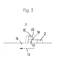
- the fuse link generally designated 1 in the embodiments shown here is attached via its grip tab 2 in the suspension parts 4 forming an insertion slot 3
- the suspension parts 4 are in the cover 6.
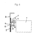
- the front cover of the cover 8 is closed at the front by a sliding window 9, in the test holes above and below 10 are provided for the voltage test.
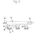
- the switch frame 5 has phase partitions 24, which are between the fuse inserts 1 not shown up to the position of the Slider 14 extend.
- Cover 6 can be pivoted about pivot point 25 using bearing guide 26 can be pivoted up into the open position (not shown) by pulling the handle 7 in Figure 1 moves to the left and in Figure 2 to the left.
- the switch frame 5 is on the mounting holes 27 for mounting on a base plate, for example on the plate of a closet.
- the upper part of the cover front wall 8 is perpendicular in one plane cut to the paper plane of Figure 1 and through the longitudinal direction 11.
- the cover is also stiffened by this guide bracket 29 The place within this guide angle 29 behind the sliding window 9 is just enough for Recording of the hollow, cross-sectionally U-shaped box profile of the slide 14 on the outside at the free end of the upper leg of the U, the bars 15 are formed vertically upright.
- the cross-sectional design of the slide 14 of the other embodiment shown in FIG. 5 is structured similarly.
- the user can push the slide by pressing in the transverse direction 12 14 push against the force of the compression spring 16 out of the position shown in FIG.
Landscapes
- Fuses (AREA)
- Switch Cases, Indication, And Locking (AREA)
- Push-Button Switches (AREA)
- Keying Circuit Devices (AREA)
Applications Claiming Priority (2)
| Application Number | Priority Date | Filing Date | Title |
|---|---|---|---|
| DE19615444A DE19615444A1 (de) | 1996-04-19 | 1996-04-19 | Verriegelungseinrichtung für Sicherungseinsätze in einem Trennschalter |
| DE19615444 | 1996-04-19 |
Publications (3)
| Publication Number | Publication Date |
|---|---|
| EP0802551A2 EP0802551A2 (de) | 1997-10-22 |
| EP0802551A3 EP0802551A3 (de) | 1998-01-28 |
| EP0802551B1 true EP0802551B1 (de) | 2001-12-05 |
Family
ID=7791710
Family Applications (1)
| Application Number | Title | Priority Date | Filing Date |
|---|---|---|---|
| EP97102389A Expired - Lifetime EP0802551B1 (de) | 1996-04-19 | 1997-02-14 | Verriegelungseinrichtung für Sicherungseinsätze in einem Trennschalter |
Country Status (4)
| Country | Link |
|---|---|
| EP (1) | EP0802551B1 (pl) |
| AT (1) | ATE210335T1 (pl) |
| DE (2) | DE19615444A1 (pl) |
| PL (1) | PL182231B1 (pl) |
Families Citing this family (3)
| Publication number | Priority date | Publication date | Assignee | Title |
|---|---|---|---|---|
| DE19849875C1 (de) * | 1998-10-29 | 2000-02-17 | Geyer Ag | Verriegelungseinrichtung für einen zwei- oder vierpoligen, aus einzeln betätigbaren Polen zusammengesetzten NH-Sicherungstrenner oder NH-Sicherungslasttrenner |
| DE102006049812A1 (de) * | 2006-10-17 | 2008-04-24 | Siemens Ag | Sicherungslasttrennschalter und Verriegelungseinrichtung für einen Sicherungslasttrennschalter |
| PL220874B1 (pl) * | 2010-09-10 | 2016-01-29 | APATOR Spółka Akcyjna | Łącznik elektryczny z blokadą wyjęcia pokrywy |
Family Cites Families (9)
| Publication number | Priority date | Publication date | Assignee | Title |
|---|---|---|---|---|
| DE1106836B (de) * | 1956-03-15 | 1961-05-18 | Pfisterer Elektrotech Karl | Mehrpoliger Sicherungstrennschalter mit von aussen einzeln loesbaren Sicherungen |
| DE2254847B2 (de) * | 1972-11-09 | 1978-11-30 | Licentia Patent-Verwaltungs-Gmbh, 6000 Frankfurt | Einfahr-Anordnung |
| DE7417818U (de) * | 1974-05-22 | 1974-09-19 | Siemens Ag | Griffeinsatz zur Aufnahme von mehreren, auswechselbaren Schmelzsicherungseinsätzen |
| DE7503203U (de) * | 1975-02-04 | 1975-06-05 | Driescher F Spezialfabrik Fuer Elek | Haltevorrichtung tür Sicherungseinsätze |
| DE2551422C3 (de) * | 1975-11-15 | 1979-05-03 | Christian Geyer Gmbh & Co, 8500 Nuernberg | Niederspannungs-Hochleistungs-Lastschaltsicherung |
| CH619320A5 (en) * | 1977-10-03 | 1980-09-15 | Weber Ag Fab Elektro | Operating handle for a low-voltage, high-rupture-capacity (NH) fuse |
| NL9100415A (nl) * | 1991-03-07 | 1992-10-01 | Tech Handelsmaatschappij Distr | Samenstel van een elektrische schakelaar en een zekeringhouder. |
| DE9305969U1 (de) * | 1993-04-20 | 1993-07-01 | Christian Geyer GmbH & Co, 8500 Nürnberg | NH-Sicherung |
| DE9403039U1 (de) * | 1994-02-24 | 1994-07-28 | Peterreins Schalttechnik GmbH, 91126 Schwabach | Mit Sicherungen versehene Schaltanordnung |
-
1996
- 1996-04-19 DE DE19615444A patent/DE19615444A1/de not_active Withdrawn
-
1997
- 1997-02-14 EP EP97102389A patent/EP0802551B1/de not_active Expired - Lifetime
- 1997-02-14 AT AT97102389T patent/ATE210335T1/de active
- 1997-02-14 DE DE59705613T patent/DE59705613D1/de not_active Expired - Lifetime
- 1997-04-17 PL PL97319530A patent/PL182231B1/pl unknown
Also Published As
| Publication number | Publication date |
|---|---|
| ATE210335T1 (de) | 2001-12-15 |
| PL182231B1 (pl) | 2001-11-30 |
| PL319530A1 (en) | 1997-10-27 |
| EP0802551A3 (de) | 1998-01-28 |
| DE19615444A1 (de) | 1997-10-23 |
| DE59705613D1 (de) | 2002-01-17 |
| EP0802551A2 (de) | 1997-10-22 |
Similar Documents
| Publication | Publication Date | Title |
|---|---|---|
| EP1993116B1 (de) | Sicherungslastschaltleiste | |
| DE4210953C2 (de) | Lastschaltleiste | |
| EP0802551B1 (de) | Verriegelungseinrichtung für Sicherungseinsätze in einem Trennschalter | |
| DE69523579T2 (de) | Gehäuse für ein elektrisches Gerät | |
| EP1246213B1 (de) | Lastschaltleiste für die Grösse 00 | |
| EP0711004A2 (de) | Vorrichtung zum Montieren schwerer elektrischer Steckverbindereinsätze auf Tragschienen | |
| DE2819812A1 (de) | Zubehoer fuer gehaeuseprofile | |
| DE202006016486U1 (de) | Elektronikgehäuse | |
| EP1430579A1 (de) | Sockel für einen schaltschrank | |
| CH615292A5 (pl) | ||
| DE3437585C2 (pl) | ||
| DE3602730C1 (en) | Distribution box for telecommunications cables | |
| DE29807106U1 (de) | Elektrisches Installationsgerät, insbesondere zur Aufputz-Montage | |
| DE10054168A1 (de) | Sicherungleiste | |
| DE3922882C2 (de) | Verriegelbare Steckverbindung | |
| DE69500153T2 (de) | Strukturelement für einen Gestellrahmen eines Schaltschranks | |
| DE2102385C3 (de) | Tastenschalter-Tableau-Mechanik | |
| WO2008071424A2 (de) | Montagesystem für schienenmontable gehäuse | |
| DE8900097U1 (de) | Duschabtrennung | |
| DE2651589A1 (de) | Klemmengehaeuse fuer elektrische reihenklemmen | |
| EP0348790B1 (de) | Schublade od. dgl. mit mindestens einem verstellbaren Trennschied | |
| DE29605800U1 (de) | Lastschaltleiste mit einem Gehäuse und mit einem Deckel | |
| EP0424747B1 (de) | Verbindung zweier Gehäuseteile insbesondere des Sockels eines Kabelverteilerschrankes mit dessen Aufbau | |
| DE29714134U1 (de) | Verriegelungsschieber für Sicherung | |
| DE29610554U1 (de) | Elektrisches Installationsgerät insbesondere zur Aufputz-Montage |
Legal Events
| Date | Code | Title | Description |
|---|---|---|---|
| PUAI | Public reference made under article 153(3) epc to a published international application that has entered the european phase |
Free format text: ORIGINAL CODE: 0009012 |
|
| AK | Designated contracting states |
Kind code of ref document: A2 Designated state(s): AT BE CH DE LI |
|
| AX | Request for extension of the european patent |
Free format text: SI PAYMENT 970225 |
|
| PUAL | Search report despatched |
Free format text: ORIGINAL CODE: 0009013 |
|
| AK | Designated contracting states |
Kind code of ref document: A3 Designated state(s): AT BE CH DE LI |
|
| AX | Request for extension of the european patent |
Free format text: SI PAYMENT 970225 |
|
| 17P | Request for examination filed |
Effective date: 19980218 |
|
| 17Q | First examination report despatched |
Effective date: 20000201 |
|
| GRAG | Despatch of communication of intention to grant |
Free format text: ORIGINAL CODE: EPIDOS AGRA |
|
| GRAG | Despatch of communication of intention to grant |
Free format text: ORIGINAL CODE: EPIDOS AGRA |
|
| GRAH | Despatch of communication of intention to grant a patent |
Free format text: ORIGINAL CODE: EPIDOS IGRA |
|
| GRAH | Despatch of communication of intention to grant a patent |
Free format text: ORIGINAL CODE: EPIDOS IGRA |
|
| GRAA | (expected) grant |
Free format text: ORIGINAL CODE: 0009210 |
|
| AK | Designated contracting states |
Kind code of ref document: B1 Designated state(s): AT BE CH DE LI |
|
| AX | Request for extension of the european patent |
Free format text: SI PAYMENT 19970225 |
|
| PG25 | Lapsed in a contracting state [announced via postgrant information from national office to epo] |
Ref country code: BE Free format text: LAPSE BECAUSE OF FAILURE TO SUBMIT A TRANSLATION OF THE DESCRIPTION OR TO PAY THE FEE WITHIN THE PRESCRIBED TIME-LIMIT Effective date: 20011205 |
|
| REF | Corresponds to: |
Ref document number: 210335 Country of ref document: AT Date of ref document: 20011215 Kind code of ref document: T |
|
| REG | Reference to a national code |
Ref country code: CH Ref legal event code: EP |
|
| RAP2 | Party data changed (patent owner data changed or rights of a patent transferred) |
Owner name: EFEN GMBH |
|
| REF | Corresponds to: |
Ref document number: 59705613 Country of ref document: DE Date of ref document: 20020117 |
|
| REG | Reference to a national code |
Ref country code: CH Ref legal event code: NV Representative=s name: ISLER & PEDRAZZINI AG |
|
| PLBE | No opposition filed within time limit |
Free format text: ORIGINAL CODE: 0009261 |
|
| STAA | Information on the status of an ep patent application or granted ep patent |
Free format text: STATUS: NO OPPOSITION FILED WITHIN TIME LIMIT |
|
| 26N | No opposition filed | ||
| PGFP | Annual fee paid to national office [announced via postgrant information from national office to epo] |
Ref country code: CH Payment date: 20070214 Year of fee payment: 11 |
|
| REG | Reference to a national code |
Ref country code: CH Ref legal event code: PCAR Free format text: ISLER & PEDRAZZINI AG;POSTFACH 1772;8027 ZUERICH (CH) |
|
| REG | Reference to a national code |
Ref country code: CH Ref legal event code: PL |
|
| PG25 | Lapsed in a contracting state [announced via postgrant information from national office to epo] |
Ref country code: LI Free format text: LAPSE BECAUSE OF NON-PAYMENT OF DUE FEES Effective date: 20080229 Ref country code: CH Free format text: LAPSE BECAUSE OF NON-PAYMENT OF DUE FEES Effective date: 20080229 |
|
| PGFP | Annual fee paid to national office [announced via postgrant information from national office to epo] |
Ref country code: AT Payment date: 20160218 Year of fee payment: 20 |
|
| PGFP | Annual fee paid to national office [announced via postgrant information from national office to epo] |
Ref country code: DE Payment date: 20160429 Year of fee payment: 20 |
|
| REG | Reference to a national code |
Ref country code: DE Ref legal event code: R071 Ref document number: 59705613 Country of ref document: DE |
|
| REG | Reference to a national code |
Ref country code: AT Ref legal event code: MK07 Ref document number: 210335 Country of ref document: AT Kind code of ref document: T Effective date: 20170214 |