EP0802551B1 - Locking device for cartridge fuses in an isolating switch - Google Patents
Locking device for cartridge fuses in an isolating switch Download PDFInfo
- Publication number
- EP0802551B1 EP0802551B1 EP97102389A EP97102389A EP0802551B1 EP 0802551 B1 EP0802551 B1 EP 0802551B1 EP 97102389 A EP97102389 A EP 97102389A EP 97102389 A EP97102389 A EP 97102389A EP 0802551 B1 EP0802551 B1 EP 0802551B1
- Authority
- EP
- European Patent Office
- Prior art keywords
- locking
- slider
- low
- cover
- break switch
- Prior art date
- Legal status (The legal status is an assumption and is not a legal conclusion. Google has not performed a legal analysis and makes no representation as to the accuracy of the status listed.)
- Expired - Lifetime
Links
Images


Classifications
-
- H—ELECTRICITY
- H01—ELECTRIC ELEMENTS
- H01H—ELECTRIC SWITCHES; RELAYS; SELECTORS; EMERGENCY PROTECTIVE DEVICES
- H01H85/00—Protective devices in which the current flows through a part of fusible material and this current is interrupted by displacement of the fusible material when this current becomes excessive
- H01H85/02—Details
- H01H85/0208—Tools for inserting and removing fuses
-
- H—ELECTRICITY
- H01—ELECTRIC ELEMENTS
- H01H—ELECTRIC SWITCHES; RELAYS; SELECTORS; EMERGENCY PROTECTIVE DEVICES
- H01H31/00—Air-break switches for high tension without arc-extinguishing or arc-preventing means
- H01H31/02—Details
- H01H31/12—Adaptation for built-in fuse
- H01H31/122—Fuses mounted on, or constituting the movable contact parts of, the switch
Definitions
- the invention relates to a NH fuse switch disconnector with switch frame and with respect to this Movable cover, in which the fuse links next to each other transversely to their longitudinal direction arranged, separated from each other by at least one phase partition and by means of their Handle straps are held by suspension parts, with a device for releasable locking of fuse links is provided, in each of which a spring-loaded bolt with the respective grip tab can be brought into locking engagement, with at least two bolts on a common slide are attached, which counter to the biasing force of a spring is displaceable and brings the latches from the handle tabs out of locking engagement.
- DE 74 17 818 U1 shows a tool designed as a handle insert with which several Fuse links can be pulled out of their circuits or inserted into them.
- the tool has T-shaped recesses into which the tabs of the fuse links are inserted can be used.
- a locking bar can be moved lengthways using a handle the fuse links are moved so that part of the T-shaped recesses is blocked and the grip tabs are held securely in the tool.
- the object of the invention is therefore to provide a NH fuse switch disconnector of the type mentioned to create, in which the removal of the fuse links easily, with great reliability and can be done at any time without touching personnel.
- this object is achieved in that the slide crosswise in the transverse direction is displaceable to the longitudinal direction of the fuse links arranged in the disconnector and that it extends through a side wall of the lid to form a button.
- the Slider thus extends at least over one, preferably over two or three side by side arranged fuse links in this cross direction, because the fuse links sit crosswise so that their longitudinal directions are parallel.
- the preload the spring naturally also acts in this transverse direction, because it presses the Slider in locking engagement. Without touching a fuse link by the hand of a Users can remove one or even three fuse links from the cover at the same time of a switch disconnector. So even with very warm fuse links a removal possible immediately after switching off the consumer.
- the lid is on one embodiment pivotable relative to the switch frame. It is also particularly advantageous the possibility to make the cover removable from the switch frame. The unlocking is evident and removing the fuse links easily and without problems and risk of injury possible.
- the button extending through the side wall of the cover in the said transverse direction protrudes half a finger width laterally out of the side wall. This is the key easily accessible for every user. But it can also be useful at the point of passage a small recess in the side wall of the button so that the button accessible and to be operated by the user in the same way from the outside, nevertheless the outer contour of the entire lid is not exceeded. This allows compact Mount the switch disconnectors close together so that they do little Need space.
- the bolt is as a web with the Slider connected hook formed, which engages around the grip tab.
- This structure advantageously allows the arrangement of the plate-shaped or substantially flat Handle tab between the slide on the one hand and the hook or bolt on the other.
- the rest- or locking surface of the hook encompasses the grip tab in this way.
- the unwanted pressing out of the grip tab in the longitudinal direction of the fuse link avoid upwards by the hook that grips the handle tab from above, while below, i.e. with regard to the tab on the side opposite the hook of the slider is arranged.
- the slide has an elongated box profile and at the end opposite the key receives a compression spring.
- the slide can be for example, from solid, electrically insulating and durable plastic or injection molding.
- the mentioned one can Compression spring can be received and locked in the cavity of this slide. It supports itself against the side wall of the cover or an intermediate web in the cover, which is opposite the side wall with the recessed grip through which the button protrudes.
- the slide can also be fastened between one on the cover Arrange the guide bracket and a preferably removable cover front wall in a sliding manner.
- This configuration significantly improves the installation of the slide with or without its hook.
- the slider is elongated and arranged side by side over all three Fuse links, he can from, i.e. simple from the front wall of the lid be used without unscrewing other parts on the cover beforehand.
- a part of the front cover as a window or is even designed as a sliding window. You can do this with the right construction for the Assemble the slider, then snap the slider in the shape of the elongated one Insert the box profile against the compression spring and then the window again snap in.
- the guide angle mentioned which in cross section is L-shaped in one embodiment is, can have legs so long that the leg heights the cross-sectional dimensions of the Slide. Then the tab can like the L-shaped guide bracket up complete the second free leg of a U.
- the slidable reciprocating slider is then enclosed between the handle tab and the guide bracket as in a cage. According to either the front wall of the cover or its sliding window can close the guide bracket close a closed box housing. Tilting and jamming of the slide before and while pressing the button is then excluded.
- a sliding window With a test hole for voltage measurement, the hole can be pushed through the slide be covered. After pushing up this window, the hole of the covering walls (e.g. the slide) vertically in the longitudinal direction of the fuse link away and clears the space behind to the grip tab for voltage measurement.
- the slide and the latches are in one plane the hanging parts leaving an insertion slot and behind the front cover wall are movable.
- the elongated slide can be thought of as being placed in a vertical plane, which is parallel to the front wall of the lid. The normal direction of view is then perpendicular to this Level.
- this is the one considered here preferred embodiment opposite to the viewing direction close (1- 5 mm) in front, or that The window or the sliding window is there. Between this front cover or the The window or the sliding window is there.
- an inlet slope is formed similar to other spring-loaded bolts can also be the plate to be locked here considered embodiment namely the grip tab, when pushing in against the Run in chamfer and thus counter the spring pressure in the longitudinal direction of the Push the slide away so that the locking surface or locking surface when inserting the grip tab is pushed to its end position to the side after positioning the Snap the grip tab back into locking engagement.
- the inlet slope should be on the restricted area of the Riegel's opposite side or next to it. You then need to insert the Locking tabs are not a special tool to slide the slide in with its bolts to bring the unlocking position.
- Another advantageous embodiment of the invention is characterized in that Slider approximately perpendicular to its longitudinal and sliding direction at a distance from each other protrude arranged blocking webs. Similar to the first considered embodiment with the hook-shaped bolt, which is also connected to the slider via a web, the bars themselves are designed as such bridges. The hook at the end is missing this Embodiment does not encompass the grip tabs to be locked but lies down on one side in front of this, so that the tabs on this side are not without deliberate unlocking can be taken out or fall out.
- the number of blocking bars corresponds to Number of fuse links to be locked in the switch disconnector.
- the fuse link generally designated 1 in the embodiments shown here is attached via its grip tab 2 in the suspension parts 4 forming an insertion slot 3
- the suspension parts 4 are in the cover 6.
- the front cover of the cover 8 is closed at the front by a sliding window 9, in the test holes above and below 10 are provided for the voltage test.
- the switch frame 5 has phase partitions 24, which are between the fuse inserts 1 not shown up to the position of the Slider 14 extend.
- Cover 6 can be pivoted about pivot point 25 using bearing guide 26 can be pivoted up into the open position (not shown) by pulling the handle 7 in Figure 1 moves to the left and in Figure 2 to the left.
- the switch frame 5 is on the mounting holes 27 for mounting on a base plate, for example on the plate of a closet.
- the upper part of the cover front wall 8 is perpendicular in one plane cut to the paper plane of Figure 1 and through the longitudinal direction 11.
- the cover is also stiffened by this guide bracket 29 The place within this guide angle 29 behind the sliding window 9 is just enough for Recording of the hollow, cross-sectionally U-shaped box profile of the slide 14 on the outside at the free end of the upper leg of the U, the bars 15 are formed vertically upright.
- the cross-sectional design of the slide 14 of the other embodiment shown in FIG. 5 is structured similarly.
- the user can push the slide by pressing in the transverse direction 12 14 push against the force of the compression spring 16 out of the position shown in FIG.
Abstract
Description
Die Erfindung betrifft einen NH-Sicherungslasttrenner mit Schaltergestell und bezüglich diesem bewegbaren Deckel, bei dem die Sicherungseinsätze quer zu ihrer Längsrichtung nebeneinander angeordnet, durch wenigstens eine Phasentrennwand voneinander getrennt und mittels ihrer Grifflaschen von Aufhängeteilen gehalten sind, wobei eine Einrichtung zum lösbaren Verriegeln von Sicherungseinsätzen vorgesehen ist, bei der jeweils ein federnd vorgespannter Riegel mit der jeweiligen Grifflasche in Verriegelungseingriff bringbar ist, wobei mindestens zwei Riegel an einem gemeinsamen Schieber angebracht sind, der entgegen der Vorspannkraft einer Feder verschiebbar ist und dabei die Riegel von den Grifflaschen außer Verriegelungseingriff bringt.The invention relates to a NH fuse switch disconnector with switch frame and with respect to this Movable cover, in which the fuse links next to each other transversely to their longitudinal direction arranged, separated from each other by at least one phase partition and by means of their Handle straps are held by suspension parts, with a device for releasable locking of fuse links is provided, in each of which a spring-loaded bolt with the respective grip tab can be brought into locking engagement, with at least two bolts on a common slide are attached, which counter to the biasing force of a spring is displaceable and brings the latches from the handle tabs out of locking engagement.
Es ist bekannt, Sicherungseinsätze in NH-Sicherungslasttrennschaltern oder -leisten herausnehmbar anzubringen, um Verbraucher mit diesen Schaltern ein- oder auszuschalten. Der relativ zum Schaltergestell herausschwenkbare und wieder an diesen heranschwenkbare Deckel trägt bei diesen Schaltern die Sicherungseinsätze, die bei einem aus dem Betrieb bekannten Lasttrennschalter zu dritt nebeneinander angeordnet sind, jeweils ein Einsatz für eine Phase (RST). Deshalb sind an den Deckeln der bekannten Schalter Aufhängeteile für die Aufnahme von Grifflaschen angebracht. Durch das Herausschwenken und auch Hineindrücken der Deckel auf die Schaltergestelle treten Fliehkräfte auf, welche nicht gesicherte Sicherungseinsätze von den Aufhängeteilen außer Eingriff drücken würden. Bei manchen Schaltern werden die Sicherungseinsätze so befestigt, daß man zuerst eine untere Kontaktfeder in Eingriff bringt, danach über das Zuschwenken die obere Kontaktfeder, wodurch auch axiale Kraftkomponenten auftreten, die ein Herausschieben des betreffenden Sicherungseinsatzes aus seiner Verankerung im Deckel bewirken können.It is known to remove fuse links in NH fuse switch disconnectors or strips attached to switch consumers on or off with these switches. The relative to The switch frame can be swung out and swung back onto the cover Switches the fuse links that are used in a switch disconnector known from operation three of them are arranged side by side, one insert for each phase (RST). Therefore are on the lids of the known switch hanging parts for receiving handle straps attached. Step out of the switch frames by swiveling them out and pushing them in Centrifugal forces on which unsecured fuse links disengage from the suspension parts would push. With some switches, the fuse links are attached so that first engages a lower contact spring, then swivels the upper contact spring, whereby also axial force components occur that push the relevant one out Can cause fuse insert from its anchoring in the lid.
Aus diesem Grund hat man die jeweilige Grifflasche in den Aufhängeteilen verriegelt. Bei einer bekannten Lösung ist in Längsrichtung des Sicherungseinsatzes außerhalb der ersten Grifflasche ein Riegel aus Kunststoff federnd so vorgespannt angeordnet, daß die Grifflasche beim Einsetzen den Riegel in Längsrichtung des Sicherungseinsatzes durch manuelle Kraft nach vom drückt, so daß der Benutzer danach die hintere Grifflasche in die Aufhängeteile herunterdrücken und einsetzen kann. Die Feder hinter dem Riegel drückt den Sicherungseinsatz über die Grifflasche so weit nach hinten, daß auch die hintere Grifflasche in die dortigen Ausnehmungen eingreift und der Sicherungseinsatz fest verriegelt ist. Bei dieser bekannten Lösung handelt es sich um eine form- und kraftschlüssige Verriegelung, die man dadurch wieder auflöst, daß man mit der Hand eine derart große Kraft aufbringt, daß die vordere Grifflasche den Riegel zurückschieben kann.For this reason, the respective handle tab has been locked in the hanging parts. At a known solution is in the longitudinal direction of the fuse link outside the first tab a plastic latch arranged resiliently biased so that the handle tab when inserted pushes the bolt in the longitudinal direction of the fuse link by manual force, so that the user then push the rear grip tab down into the hanging parts and insert it can. The spring behind the bolt pushes the fuse link over the handle tab so far to the rear, that the rear grip tab also engages in the recesses there and the fuse link is firmly locked. This known solution is a form and non-positive locking, which can be released by having such a hand exerts great force so that the front grip tab can push the bolt back.
Es hat sich gezeigt, daß bei dieser wie auch bei anderen aus der Praxis bekannten Verriegelungen von Sicherungseinsätzen das Personal jeden einzelnen Sicherungseinsatz anfassen und entgegen dem Sperrdruck des Riegels drücken muß und dann erst herausnehmen kann. Häufig erfolgt eine solche Entnahme nach dem Betrieb. Durch den Betrieb erwärmt sich der Sicherungseinsatz zum Teil nicht unerheblich, so daß sich die Bedienungsperson verbrennen und verletzen kann.It has been shown that with this as well as with other interlocks known from practice of security interventions, the staff should touch and counter each individual security interlock must press the locking pressure of the bolt and only then can it be removed. One often occurs such removal after operation. The fuse link heats up during operation Part not insignificant, so that the operator can burn and injure himself.
Es gibt auch Geräte in der Praxis, bei denen die betreffende Bedienungsperson außer dem Anfassen des Sicherungseinsatzes den Riegel mit einem besonderen Werkzeug zusätzlich entsperren muß, und solche Zugriffe sind wegen der engen Platzverhältnisse schwierig.There are also devices in practice in which the operator concerned besides touching unlock the bolt with a special tool must, and such accesses are difficult because of the limited space.
Die DE 74 17 818 U1 zeigt ein als Griffeinsatz ausgebildetes Werkzeug, mit dem mehrere Schmelzsicherungseinsätze aus ihren Stromkreisen gezogen bzw. in diese eingesetzt werden können. Dazu weist das Werkzeug T-förmige Ausnehmungen auf, in die die Grifflaschen der Sicherungseinsätze eingesetzt werden können. Ein Riegelglied kann mit Hilfe einer Handhabe in Längsrichtung der Sicherungseinsätze bewegt werden, so daß ein Teil der T-förmigen Ausnehmungen blockiert wird und die Grifflaschen in dem Werkzeug sicher gehalten werden. DE 74 17 818 U1 shows a tool designed as a handle insert with which several Fuse links can be pulled out of their circuits or inserted into them. For this purpose, the tool has T-shaped recesses into which the tabs of the fuse links are inserted can be used. A locking bar can be moved lengthways using a handle the fuse links are moved so that part of the T-shaped recesses is blocked and the grip tabs are held securely in the tool.
Die DE 94 03 039 U1 zeigt einen NH-Sicherungslasttrenner der gattungsbildenden Art. Hierbei sind die Riegel mit den Aufhängeteilen identisch, so daß die Sicherungseinsätze lediglich im Verriegelungszustand mittels ihrer Grifflaschen gehalten werden. Auch hier können die Riegel in Längsrichtung der im Trennschalter angeordneten Sicherungseinsätze verschoben werden. Diese Ausführungsform hat jedoch den Nachteil, daß die Verriegelungseinrichtung eine große räumliche Ausdehnung hat und die Schaltkräfte über die Riegel auf die Grifflaschen der Sicherungen übertragen werden.DE 94 03 039 U1 shows an NH fuse-switch disconnector of the generic type the bolts are identical to the suspension parts, so that the fuse links only in the locked state are held by means of their tabs. Here, too, the bolts can be moved lengthways the fuse links arranged in the disconnector are moved. This embodiment has the disadvantage, however, that the locking device has a large spatial extent and transmits the switching forces via the bolts to the tabs on the fuses become.
Aufgabe der Erfindung ist es daher, einen NH-Sicherungslasttrenner der eingangs genannten Art zu schaffen, bei welchem die Entnahme der Sicherungseinsätze einfach, mit großer Zuverlässigkeit und ohne Berührung durch Personal jederzeit vorgenommen werden kann.The object of the invention is therefore to provide a NH fuse switch disconnector of the type mentioned to create, in which the removal of the fuse links easily, with great reliability and can be done at any time without touching personnel.
Gemäß der Erfindung wird diese Aufgabe dadurch gelöst, daß der Schieber in Querrichtung quer zur Längsrichtung der im Trennschalter angeordneten Sicherungseinsätze verschiebbar ist und daß er sich unter Bildung einer Taste durch eine Seitenwand des Deckels erstreckt.According to the invention, this object is achieved in that the slide crosswise in the transverse direction is displaceable to the longitudinal direction of the fuse links arranged in the disconnector and that it extends through a side wall of the lid to form a button.
Die Entnahme der Sicherungseinsätze vor oder nach dem Betrieb, d. h. nach dem Abschalten der Energie, wird bei einer Einrichtung mit den vorstehend genannten Maßnahmen erheblich vereinfacht. Die Bedienungsperson braucht nur auf die aus der einen Seitenwand hervorstehende Taste zu drücken und kann damit gleichzeitig wenigstens zwei Sicherungseinsätze derart entriegeln, daß beide Einsätze beim Umkippen des Deckels oder Schräghalten fast gleichzeitig herausfallen. Kein Sicherungseinsatz braucht mehr von Hand angefaßt oder gar gedrückt zu werden. Wenn die Taste von der gegenüberliegenden Seitenwand nicht weniger als eine Handbreite entfernt ist, wie dies bei kleineren Trennschaltern der Fall ist, zum Beispiel der Größe 00, dann kann der Benutzer mit einer Hand entriegeln. Der Daumen greift dabei auf die eine Seitenwand und einer der Finger auf die gegenüberliegend herausstehende Taste. Die Taste wird in die erwähnte Querrichtung gedrückt, d. h. quer zur Längsrichtung der Sicherungseinsätze. Deren Längsrichtung ist in Richtung der beiden entgegengesetzten Kontaktmesser bzw. der Verbindungslinie zwischen diesen angenommen. Der Schieber erstreckt sich also wenigstens über einen, vorzugsweise über zwei oder drei nebeneinander angeordnete Sicherungseinsätze in dieser erwähnten Querrichtung, denn die Sicherungseinsätze sitzen quer so nebeneinander, daß ihre Längsrichtungen jeweils parallel liegen. Die Vorspannkraft der Feder wirkt selbstverständlich ebenfalls in dieser Querrichtung, denn sie drückt den Schieber in Verriegelungseingriff. Ohne Berührung eines Sicherungseinsatzes durch die Hand eines Benutzers kann der eine oder können sogar drei Sicherungseinsätze gleichzeitig vom Deckel eines Lasttrennschalters gelöst werden. Auch bei stark erwärmten Sicherungseinsätzen ist also eine Entnahme unmittelbar nach dem Abschalten des Verbrauchers möglich. Der Deckel ist bei einer Ausführungsform gegenüber dem Schaltergestell schwenkbar. Besonders vorteilhaft ist auch die Möglichkeit, den Deckel vom Schaltergestell entnehmbar zu gestalten. Ersichtlich ist das Entriegeln und Entnehmen der Sicherungseinsätze einfach und ohne Probleme und Verletzungsgefahr möglich.The removal of the fuse links before or after operation, d. H. after switching off the Energy is significantly simplified in a facility with the measures mentioned above. The operator only needs to press the button protruding from one side wall to press and can thus simultaneously unlock at least two fuse links such that both inserts fall out almost simultaneously when the lid is tipped over or held at an angle. No The fuse link needs to be handled more by hand or even pressed. If the button is no less than a hand's width from the opposite side wall, as in smaller disconnectors is the case, for example size 00, then the user can use a Unlock hand. The thumb grips one side wall and one of the fingers on the key protruding opposite. The key is pressed in the mentioned transverse direction, i. H. transverse to the longitudinal direction of the fuse links. Their longitudinal direction is in the direction of the two opposite contact knife or the connecting line between them assumed. The Slider thus extends at least over one, preferably over two or three side by side arranged fuse links in this cross direction, because the fuse links sit crosswise so that their longitudinal directions are parallel. The preload the spring naturally also acts in this transverse direction, because it presses the Slider in locking engagement. Without touching a fuse link by the hand of a Users can remove one or even three fuse links from the cover at the same time of a switch disconnector. So even with very warm fuse links a removal possible immediately after switching off the consumer. The lid is on one embodiment pivotable relative to the switch frame. It is also particularly advantageous the possibility to make the cover removable from the switch frame. The unlocking is evident and removing the fuse links easily and without problems and risk of injury possible.
Die sich durch die Seitenwand des Deckels in der genannten Querrichtung erstreckende Taste ragt einen halben Fingerbreit in Querrichtung seitlich aus der Seitenwand heraus. Dadurch ist die Taste für jeden Benutzer gut zugänglich. Es kann aber auch zweckmäßig sein, an der Stelle des Durchtritts der Taste nach außen in der Seitenwand eine kleine Mulde anzubringen, so daß die Taste zwar von dem Benutzer außen in gleicher Funktionsweise zugänglich und zu betätigen ist, gleichwohl die Außenkontur des gesamten Deckels nicht überschritten wird. Dadurch können bei kompakten Montagen die Lasttrennschalter dicht nebeneinander angeordnet werden, so daß sie wenig Platz benötigen. The button extending through the side wall of the cover in the said transverse direction protrudes half a finger width laterally out of the side wall. This is the key easily accessible for every user. But it can also be useful at the point of passage a small recess in the side wall of the button so that the button accessible and to be operated by the user in the same way from the outside, nevertheless the outer contour of the entire lid is not exceeded. This allows compact Mount the switch disconnectors close together so that they do little Need space.
Für eine wirkungsvolle Verriegelung versteht es sich, daß für einen Sicherungseinsatz ein Schieber mit Riegel nur im Bereich einer der zwei Grifflaschen vorgesehen sein muß. Die gegenüberliegende Seite ist durch die starre Verbindung der anderen Grifflasche mit dem Sicherungseinsatz gleichermaßen verriegelt.For effective locking, it goes without saying that for a fuse link Slider with latch must only be provided in the area of one of the two tabs. The opposite side is through the rigid connection of the other handle tab with the Fuse insert locked equally.
Bei weiterer vorteilhafter Ausgestaltung der Erfindung ist der Riegel als über einen Steg mit dem Schieber verbundener Haken ausgebildet, welcher die Grifflasche umgreift. Dieser Aufbau ermöglicht in vorteilhafter Weise die Anordnung der plattenförmigen bzw. im wesentlichen flachen Grifflasche zwischen dem Schieber einerseits und dem Haken bzw. Riegel andererseits. Die Rast- oder Sperrfläche des Hakens umgreift die Grifflasche auf diese Weise. Dadurch ergeben sich gute Möglichkeiten, den im Trennschalter vorhandenen Platz optimal zu nutzen. Zum Beispiel kann man das unerwünschte Herausdrücken der Grifflasche in Längsrichtung des Sicherungseinsatzes nach oben durch den Haken vermeiden, der von oben auf die Grifflasche greift, während unten, d.h. bezüglich der Grifflasche auf der dem Haken gegenüberliegenden Seite der Schieber angeordnet ist. Dieser benötigt für seine Erstreckung in der erwähnten Querrichtung einen Mindestraum, auch in der Höhe, die in Längsrichtung der Sicherungseinsätze zu sehen istIn a further advantageous embodiment of the invention, the bolt is as a web with the Slider connected hook formed, which engages around the grip tab. This structure advantageously allows the arrangement of the plate-shaped or substantially flat Handle tab between the slide on the one hand and the hook or bolt on the other. The rest- or locking surface of the hook encompasses the grip tab in this way. This results in good ones Possibilities to optimally use the space available in the disconnector. For example the unwanted pressing out of the grip tab in the longitudinal direction of the fuse link avoid upwards by the hook that grips the handle tab from above, while below, i.e. with regard to the tab on the side opposite the hook of the slider is arranged. This requires one for its extension in the transverse direction mentioned Minimum space, including the height that can be seen in the longitudinal direction of the fuse links
Es gibt Ausführungsformen, bei denen die Frontwand des Deckels durch ein Fenster oder gar durch ein Schiebefenster verschlossen ist, in welchem Prüflöcher für die Spannungsprüfung angeordnet sind. Durch das Schieben dieses Fensters kann das betreffende Loch entweder abgedeckt oder freigelegt werden. Ein Spannungsmeßwerkzeug wird durch dieses Loch bis zur Grifflasche oder Kontaktmesser hindurchgesteckt. Für dieses richtige Applizieren des Werkzeuges am Sicherungsteil ist ein Mindestplatz erforderlich. Es gibt Ausführungsformen von Lasttrennschaltern, bei welchen dieser Platz in Bezug auf die Lage der Grifflasche beschränkt ist Für eine solche Ausführungsform ist die Ausgestaltung des Riegels als Haken sehr günstig, weil der verhältnismäßig große Schieber dann auf der unteren Seite der Grifflasche und der Haken mit seiner Rast- bzw. Sperrfläche auf der Oberseite der Grifflasche anzuordnen sind.There are embodiments in which the front wall of the lid through a window or even is closed by a sliding window, in which test holes for the voltage test are arranged. By sliding this window, the hole in question can either be covered or exposed. A voltage measuring tool is through this hole to Handle tab or contact knife inserted through it. For this correct application of the tool a minimum space is required on the securing part. There are embodiments of switch disconnectors, where this space is limited in relation to the position of the grip tab For one such embodiment, the design of the bolt as a hook is very cheap because of relatively large slide then on the lower side of the handle tab and the hook with its locking or blocking surface are to be arranged on the top of the grip tab.
Günstig ist es gemäß der Erfindung ferner, wenn der Schieber ein längliches Kastenprofil hat und an dem der Taste gegenüberliegenden Ende eine Druckfeder aufnimmt. Den Schieber kann man beispielsweise aus festem, elektrisch isolierendem und haltbarem Kunststoff formen oder auch spritzgießen. Eine günstige Gestaltung für einen länglichen Schieber, der sich vorzugsweise über zwei oder drei nebeneinander angeordnete Sicherungseinsätze in der genannten Querrichtung erstreckt, ist das erwähnte Kastenprofil. Dessen Querschnitt ist U-förmig, wobei der die beiden freien Schenkel des U verbindende Mittelsteg nach vorn zur Frontwand des Deckels hin angeordnet wird. Der hohle Kasten dieses Schieberprofiles befindet sich dann hinter diesem Steg. It is also advantageous according to the invention if the slide has an elongated box profile and at the end opposite the key receives a compression spring. The slide can be for example, from solid, electrically insulating and durable plastic or injection molding. An inexpensive design for an elongated slide that preferably extends over two or three fuse links arranged side by side in the mentioned transverse direction extends, is the box profile mentioned. Its cross-section is U-shaped, with the two free leg of the U connecting middle web towards the front wall of the cover is arranged. The hollow box of this slide profile is then behind this web.
Auf der der Taste gegenüberliegenden Seite dieses länglichen Schiebers kann die erwähnte Druckfeder in dem Hohlraum dieses Schiebers aufgenommen und arretiert werden. Sie stützt sich gegen diejenige Seitenwand des Deckels oder einen zwischengeschalteten Steg im Deckel ab, welche der Seitenwand mit der Griffmulde, durch welche die Taste vorsteht, gegenüberliegt.On the side of this elongated slider opposite the button, the mentioned one can Compression spring can be received and locked in the cavity of this slide. It supports itself against the side wall of the cover or an intermediate web in the cover, which is opposite the side wall with the recessed grip through which the button protrudes.
Erfindungsgemäß kann man den Schieber auch zwischen einem am Deckel befestigten Führungswinkel und einer vorzugsweise abnehmbaren Deckelvorderwand gleitend anordnen. Diese Ausgestaltung verbessert den Einbau des Schiebers mit oder ohne seine Haken erheblich. Selbst wenn der Schieber länglich ist und sich über alle drei nebeneinander angeordnete Sicherungseinsätze erstreckt, kann er von vom, d.h. von der Deckelvorderwand her einfach eingesetzt werden, ohne etwa andere Teile am Deckel zuvor abzuschrauben. Es gibt die zuvor schon erwähnte Ausführungsform, bei welcher ein Teil der Deckelvorderwand als Fenster oder sogar als Schlebefenster ausgebildet ist. Man kann dieses bei der richtigen Konstruktion für die Montage des Schiebers herausschnappen, dann den Schieber in Form des länglichen Kastenprofils unter Vorspannen gegen die Druckfeder einsetzen und danach das Fenster wieder einschnappen.According to the invention, the slide can also be fastened between one on the cover Arrange the guide bracket and a preferably removable cover front wall in a sliding manner. This configuration significantly improves the installation of the slide with or without its hook. Even if the slider is elongated and arranged side by side over all three Fuse links, he can from, i.e. simple from the front wall of the lid be used without unscrewing other parts on the cover beforehand. There are those before already mentioned embodiment, in which a part of the front cover as a window or is even designed as a sliding window. You can do this with the right construction for the Assemble the slider, then snap the slider in the shape of the elongated one Insert the box profile against the compression spring and then the window again snap in.
Den erwähnten Führungswinkel, der im Querschnitt L-förmig bei einer Ausführungsform zu denken ist, kann derart lange Schenkel haben, daß die Schenkelhöhen den Querschnittsmaßen des Schiebers entsprechen. Dann kann die Grifflasche den L-förmigen Führungswinkel nach oben wie der zweite freie Schenkel eines U abschließen. Der gleitend hin- und herbewegbare Schieber ist dann zwischen der Grifflasche und dem Führungswinkel wie in einem Käfig eingefaßt. Nach vom hin kann entweder die Vorderwand des Deckels oder sein Schiebefenster den Führungswinkel zu einem geschlossenen Kastengehäuse abschließen. Ein Verkanten und Verklemmen des Schiebers vor und während der Betätigung der Taste ist dann ausgeschlossen. Im Falle eines Schiebefensters mit einem Prüfloch für die Spannungsmessung kann das Loch durch den Schieber abgedeckt werden. Nach Hochschieben dieses Fensters gelangt dann das Loch von den abdeckenden Wandungen (z.B. des Schiebers) vertikal in Längsrichtung des Sicherungseinsatzes weg und gibt den Raum dahinter zur Grifflasche für die Spannungsmessung frei.The guide angle mentioned, which in cross section is L-shaped in one embodiment is, can have legs so long that the leg heights the cross-sectional dimensions of the Slide. Then the tab can like the L-shaped guide bracket up complete the second free leg of a U. The slidable reciprocating slider is then enclosed between the handle tab and the guide bracket as in a cage. According to either the front wall of the cover or its sliding window can close the guide bracket close a closed box housing. Tilting and jamming of the slide before and while pressing the button is then excluded. In the case of a sliding window With a test hole for voltage measurement, the hole can be pushed through the slide be covered. After pushing up this window, the hole of the covering walls (e.g. the slide) vertically in the longitudinal direction of the fuse link away and clears the space behind to the grip tab for voltage measurement.
Es ist ferner zweckmäßig, wenn erfindungsgemäß der Schieber und die Riegel in einer Ebene vor den einen Einsteckschlitz belassenden Aufhängeteilen und hinter der Deckelvorderwand verschiebbar sind. Den länglichen Schieber kann man sich in eine vertikale Ebene gelegt denken, welche parallel zur Deckelvorderwand liegt Die normale Blickrichtung ist dann senkrecht auf diese Ebene. Bei ebener Deckelvorderwand befindet sich diese bei der hier in Betracht gezogenen bevorzugten Ausführugnsform entgegen der Blickrichtung dicht ( 1- 5 mm) davor, bzw. das Fenster oder das Schiebefenster befindet sich dort. Zwischen dieser Deckelvorderwand oder dem Fenster oder das Schiebefenster befindet sich dort. Zwischen dieser Deckelvorderwand oder dem Fenster einerseits und den Aufhängteilen am Deckel für die Grifflasche des Sicherungseinsatzes andererseits ist konstruktionsbedingt ein gewisser Platz, und genau hier wird der Schieber mit den Riegeln angeordnet, welcher durch seine Anordnung den kompakten Aufbau des gesamten Trennschalters nicht beeinträchtigt. Auch vertikal darüber außerhalb des Schiebers wird durch den Raum zwischen den Riegeln ausreichend Platz belassen, um Werkzeuge für die Spannungsprüfung gegebenenfalls bis zu den Kontaktmessern hin zu führen.It is also expedient if, according to the invention, the slide and the latches are in one plane the hanging parts leaving an insertion slot and behind the front cover wall are movable. The elongated slide can be thought of as being placed in a vertical plane, which is parallel to the front wall of the lid. The normal direction of view is then perpendicular to this Level. In the case of a flat cover front wall, this is the one considered here preferred embodiment opposite to the viewing direction close (1- 5 mm) in front, or that The window or the sliding window is there. Between this front cover or the The window or the sliding window is there. Between this front cover or the Windows on the one hand and the hanging parts on the lid for the grip tab of the fuse link on the other hand, there is a certain amount of space due to the design, and this is exactly where the slide with the Bars arranged, which by its arrangement the compact structure of the whole Disconnector not affected. Also vertically above the slide is the Leave enough space between the bars to hold tools for tension testing if necessary, lead to the contact blades.
Es ist weiterhin vorteilhaft, wenn erfindungsgemäß auf der der Sperrfläche des Riegels abgewandten Seite und/oder zwischen diesen eine Einlaufschräge ausgebildet ist Ähnlich wie bei anderen federnd vorgespannten Riegeln kann auch hier die zu verriegelnde Platte, bei der hier betrachteten Ausführungsform nämlich die Grifflasche, beim Hereindrücken gegen die Einlaufschräge anlaufen und diese damit entgegen dem Federdruck in Längsrichtung des Schiebers so wegdrücken, daß die Sperrfläche bzw. Rastfläche beim Einsetzen der Grifflasche in ihre Endposition zunächst zur Seite gedrückt wird, um nach fertiger Positionierung der Grifflasche über diese in Verriegelungseingriff zurückzuschnappen. Es sind hier unterschiedliche Hakenformen möglich. Im wesentlichen soll sich die Einlaufschräge auf der der Sperrfläche des Riegels abgewandten Seite bzw. neben dieser befinden. Man braucht dann zum Einsetzen der zu verriegelnden Grifflaschen nicht extra ein Werkzeug, um den Schieber mit seinen Riegeln in die Entriegelungsposition zu bringen.It is also advantageous if, according to the invention, on the locking surface of the bolt opposite side and / or between these an inlet slope is formed similar to other spring-loaded bolts can also be the plate to be locked here considered embodiment namely the grip tab, when pushing in against the Run in chamfer and thus counter the spring pressure in the longitudinal direction of the Push the slide away so that the locking surface or locking surface when inserting the grip tab is pushed to its end position to the side after positioning the Snap the grip tab back into locking engagement. There are different ones here Hook shapes possible. In essence, the inlet slope should be on the restricted area of the Riegel's opposite side or next to it. You then need to insert the Locking tabs are not a special tool to slide the slide in with its bolts to bring the unlocking position.
Eine andere vorteilhafte Ausgestaltung der Erfindung ist dadurch gekennzeichnet, daß von dem Schieber etwa senkrecht zu dessen Längs- und Schieberichtung im Abstand voneinander angeordnete Blockierstege vorstehen. Ähnlich wie bei der zuerst betrachteten Ausführungsform mit dem hakenförmigen Riegel, der ebenfalls über einen Steg mit dem Schieber verbunden ist, sind die Riegel hier selbst als solche Stege ausgestaltet. Der Haken an ihrem Ende fehlt Diese Ausführungsform umgreift die zu verriegelnden Grifflaschen nicht sondern legt sich von einer Seite vor diese, damit die Grifflaschen zu dieser besagten Seite nicht ohne bewußte Entriegelung herausgenommen werden oder herausfallen können. Die Anzahl der Blockierstege entspricht der Anzahl der in dem Lasttrennschalter zu verriegelnden Sicherungseinsätze.Another advantageous embodiment of the invention is characterized in that Slider approximately perpendicular to its longitudinal and sliding direction at a distance from each other protrude arranged blocking webs. Similar to the first considered embodiment with the hook-shaped bolt, which is also connected to the slider via a web, the bars themselves are designed as such bridges. The hook at the end is missing this Embodiment does not encompass the grip tabs to be locked but lies down on one side in front of this, so that the tabs on this side are not without deliberate unlocking can be taken out or fall out. The number of blocking bars corresponds to Number of fuse links to be locked in the switch disconnector.
Weitere Vorteile, Merkmale und Anwendungsmöglichkeiten der vorliegenden Erfindung ergeben sich aus der folgenden Beschreibung bevorzugter Ausführungsbeispiele in Verbindung mit den anliegenden Zeichnungen. Es zeigen:
- Figur 1
- die Draufsicht auf einen NH-Sicherungslasttrennschalter für drei nebeneinander angeordnete Sicherungseinsätze, die hier aber nicht gezeigt sind,
Figur 2- eine Seitenansicht auf den Trennschalter der Figur 1, wenn man in Figur 1 von rechts nach links blickt,
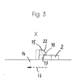
Figur 3- schematisch und abgebrochen eine Einzelheit entsprechend dem Kreis X in Figur 1,
Figur 4- eine Draufsicht auf einen abgebrochen dargestellten Sicherungseinsatz mit Grifflasche mit den Aufhängeteilen und dem gemäß Pfeil verschiebbaren hakenförmigen Riegel,
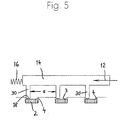
Figur 5- eine andere Ausführungsform des Riegels am Schieber in Form von Blockierstegen, und
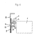
Figur 6- eine vergrößerte Querschnittsansicht eines abgebrochenen Sicherungseinsatzes mit links daneben angeordnetem Deckel und dazwischen befindlichem Schieber
- Figure 1
- the top view of a NH fuse switch disconnector for three fuse inserts arranged side by side, but which are not shown here,
- Figure 2
- 2 shows a side view of the isolating switch of FIG. 1 when looking from right to left in FIG. 1,
- Figure 3
- schematically and broken a detail corresponding to the circle X in Figure 1,
- Figure 4
- 2 shows a plan view of a safety insert, shown broken off, with a grip tab with the hanging parts and the hook-shaped bolt which can be moved according to the arrow,
- Figure 5
- another embodiment of the bolt on the slide in the form of blocking webs, and
- Figure 6
- an enlarged cross-sectional view of a broken fuse link with the lid arranged to the left and a slide located between them
Der bei den hier gezeigten Ausführungsformen allgemein mit 1 bezeichnete Sicherungseinsatz
ist über seine Grifflasche 2 in den einen Einsteckschlitz 3 bildenden Aufhängeteilen 4 befestigtThe fuse link generally designated 1 in the embodiments shown here
is attached via its
In dem in den Figuren 1 und 2 gezeigten Sicherungslasttrennschalter, der aus Schaltergestell 5
und Deckel 6 mit Griff 7 besteht, befinden sich die Aufhängeteile 4 im Deckel 6. Die Deckelvorderwand
8 ist vorn durch ein Schiebefenster 9 verschlossen, in dem oben und unten Prüflöcher
10 für die Spannungsprüfung vorgesehen sind.In the fuse switch disconnector shown in FIGS. 1 and 2, which consists of
Der Begriff "oben" und "unten" ist aus der Betrachtung der Figuren 1 und 2 genommen. Nach
oben bzw. unten erstrecken sich die strichpunktierten Linien 11 in Figur 1, welche die
Längsrichtung der in Figur 1 nicht gezeigten, aber im Trennschalter angeordneten Sicherungseinsätze
1 darstellen. Spannt man ein gedachtes Koordinatensystem auf, dann verlaufen diese die
Längsrichtung 11 veranschaulichenden Geraden in der Y-Richtung. Quer dazu, d.h. in X-Richtung
verläuft die horizontale, in Figur 1 gezeigte strichpunktierte Linie 12, welche die Querrichtung
darstellt, während in Figur 2 die horizontale strichpunktierte Linie 13 in der Z-Richtung verläuft,
welche beim Blick auf Figur 1 in Blickrichtung liegt. Entsprechend befinden sich die oberen Teile
des Trennschalters in Längsrichtung 11 in Richtung des Pfeiles +Y. Der Schieber 14 mit dem
Riegel 15 ist entgegen der X-Richtung (horizontale Linie 12) entgegen der Wirkung einer
Druckfeder 16 verschieblich.The terms “above” and “below” are taken from the consideration of FIGS. 1 and 2. To
The dash-dotted
In der hier gezeigten Ausführungsform liegen drei Sicherungseinsätze 1 In der Querrichtung 12
nebeneinander, weshalb an dem Schieber 14 auch drei Riegel 15 angeformt sind. Über den
jeweiligen Steg 17 sind bei den Ausführungsformen nach den Figuren 1 - 4 und 6 die Riegel 15
in Hakenform am Schieber 14 verbunden. Diese hakenförmigen Riegel 15 umgreifen ersichtlich
die Grifflasche 2. Mit anderen Worten befindet sich auf der einen Seite der Grifflasche 2 (unten)
der Schieber 14, und auf der gegenüberliegenden Seite greift der Riegel 15 hakenförmig so über
die Grifflasche 2, daß die in Figur 3 gezeigte Sperrfläche 18 über der Grifflasche 2 liegt mit dem
Ergebnis, daß diese sich nicht aus dem Einsteckschlitz 3 zwischen den Aufhängeteilen 4 nach
oben in Längsrichtung 11 in Richtung +Y herausbewegen können.In the embodiment shown here there are three fuse links 1 in the
Will man aber die Sicherungseinsätze 3 herausnehmen, dann drückt man auf die in Querrichtung
12 in die Mulde 19 der rechten Seitenwand 20 des Trennschalters und genauer seines Deckels
6 ragende Taste 21. Damit drückt man den Schieber 14 entgegen der Kraft der Druckfeder 16 in
Richtung -X der Querrichtung 12, d.h. in Figur 1 nach links und in Figur 2 in Blickrichtung. Auf
diese Weise bewegt sich der in den Figuren 3 und 4 vergrößert dargestellte Riegel 15 in
Querrichtung 12 aus der in Figur 3 mit ausgezogenen Linien dargestellten Verriegelungsposition
in die mit gestrichelten Linien gezeigte Entriegelungsposition. Danach schiebt die Druckfeder 16
den Schieber 14 von selbst wieder in Querrichtung 12 in die mit ausgezogenen Linien gezeigte
Positon. Zum Wiedereinsetzen wird die Grifflasche nach den Figuren 1, 3 und 6 in Längsrichtung
11 vertikal von oben nach unten gedrückt, wobei die Grifflasche 2 auf die Einlaufschräge 22 des
hakenförmigen Riegels 15 drückt und diesen ebenfalls wieder in Querrichtung 12 in die gestrichelt
gezeichnete Stellung drückt, bis die Grifflasche 2 die in Figur 3 gezeigte Position hat, so daß der
Riegel 15 wieder in Verriegelungsposition zurückgestoßen werden kann. Diese Einlaufschräge 22
ist bei der hier gezeigten Auführungsform nach den Figuren 1 und 3 auf der der Sperrfläche 18
des Riegels 15 abgewandten Seite, d.h. oben angebracht.But if you want to remove the
In Figur 1 sieht man, wie die Aufhängeteile 4 integrales Teil des Deckels 6 sind und daß der
Deckel Phasentrennwände 23 hat. Auch das Schaltergestell 5 hat Phasentrennwände 24, die sich
zwischen den nicht gezeigten Sicherungseinsätzen 1 bis nach oben über die Position des
Schiebers 14 erstrecken. Um den Drehpunkt 25 kann der Deckel 6 mit Hilfe der Lagerführung 26
in die nicht gezeigte, geöffnete Stellung heraugeschwenkt werden, indem man an dem Griff 7 in
Figur 1 nach vom und in Figur 2 nach links zieht. Das Schaltergestell 5 wird über die Befestigungsbohrungen
27 für die Grundplattenmontage an einer Grundplatte befestigt, zum Beispiel an
der Platte eines Schrankes.In Figure 1 you can see how the
In der Darstellung der Figur 6 ist der obere Teil der Deckelvorderwand 8 in einer Ebene senkrecht
zur Papierebene der Figur 1 und durch die Längsrichtung 11 gehend geschnitten. Man sieht hinter
der Deckelvorderwand 8 einen Verbindungssteg 28, der Teil eines L-förmigen Führungswinkels
29 ist, auf dessen horizontal liegendem Verbindungssteg 28 wird der Schieber 14 geführt.
Außerdem wird der Deckel zugleich durch diesen Führungswinkel 29 auch versteift Der Platz
innerhalb dieses Führungswinkels 29 hinter dem verschieblichen Fenster 9 reicht gerade für die
Aufnahme des hohlen, im Querschnitt U-förmigen Kastenprofils des Schiebers 14, an dem außen
am freien Ende des oberen Schenkels des U die Riegel 15 vertikal hochstehend angeformt sind.In the illustration in FIG. 6, the upper part of the cover
Die Querschnittsgestaltung des Schiebers 14 der anderen, in Figur 5 gezeigten Ausführungsform
ist ähnlich aufgebaut. Auch hier kann der Benutzer durch Druck in Querrichtung 12 den Schieber
14 entgegen der Kraft der Druckfeder 16 aus der in Figur 5 gezeigten Position herausschieben.The cross-sectional design of the
Etwa senkrecht zur Schieberichtung 12, die für das gesamte Gerät hier die Querrichtung genannt
ist, stehen drei Blockierstege 30 in Längsrichtung 11 der Sicherungseinsätze 1 nach unten vor.
Sie befinden sich gegenseitig in einem Abstand a voneinander. Ihre Sperrfläche 18 ist ihre
Endfläche, wenn man ihre Erstreckungsrichtung vom Schieber 14 fort betrachtet Diese
Sperrfläche 18 liegt in der Verriegelungsposition, die in Figur 5 gezeigt ist, über der Grifflasche
2 und verhindert auch hier das Herausheben derselben nach oben aus den Aufhängeteilen 4. Man
wird je nach den Platzverhältnissen im Lasttrennschalter den Schieber 14 entweder unterhalb der
Grifflaschen 2 oder im Erstreckungsabstand der Blockierstege 30 oberhalb derselben (Figur 5)
anordnen. Die Vorteile der Erfindung ergeben sich bei beiden Ausführungsformen.Approximately perpendicular to the sliding
Claims (7)
- A low-voltage HRC safety load-break switch with a switch frame (5) and a cover (6) which is movable with respect thereto, in which the safety inserts (1) are arranged in mutually juxtaposed relationship transversely with respect to their longitudinal direction (11), are separated from each other by at least one phase separating wall (23, 24) and are held by means of their gripping bars (2) by suspension members (4), wherein there is provided a device for releasably locking safety inserts (1), in which a respective resiliently biased locking bar (15) can be brought into locking engagement with the respective gripping bar (2), wherein at least two locking bars (15) are mounted on a common slider (14) which is displaceable in opposition to the biasing force of a spring (16) and in so doing takes the locking bars (15) out of locking engagement with the gripping bars (2), characterised in that the slider (14) is displaceable in the transverse direction (12) transversely with respect to the longitudinal direction (11) of the safety inserts (1) arranged in the disconnect switch and that it extends through a side wall (20) of the cover (6) forming a button (21).
- A low-voltage HRC safety load-break switch according to claim 1 characterised in that the locking bar (15) is in the form of a hook which is connected by way of a leg (17) to the slider (14) and which embraces the gripping bar (2).
- A low-voltage HRC safety load-break switch according to claim 1 or claim 2 characterised in that the slider (14) is of an elongate box-shaped profile and accommodates a compression spring (16) at the end in opposite relationship to the button (21).
- A low-voltage HRC safety load-break switch according to one of claims 1 to 3 characterised in that the slider (14) is arranged slidably between an angle guide member (29) secured to the cover (6) and a preferably removable cover front wall (8).
- A low-voltage HRC safety load-break switch according to one of claims 1 to 4 characterised in that the slider (14) and the locking bars (15) are displaceable in a plane in front of the suspension members (4) leaving an insertion slot (3) and behind the cover front wall (8).
- A low-voltage HRC safety load-break switch according to one of claims 1 to 5 characterised in that an inclined entry surface (22) is provided on the side remote from the locking surface (18) of the locking bar (15) and/or between them.
- A low-voltage HRC safety load-break switch according to one of claims 1 to 6 characterised in that blocking legs (30) arranged at a spacing from each other project from the slider (5) approximately perpendicularly to the sliding direction (12) thereof (Figure 5).
Applications Claiming Priority (2)
| Application Number | Priority Date | Filing Date | Title |
|---|---|---|---|
| DE19615444A DE19615444A1 (en) | 1996-04-19 | 1996-04-19 | Locking device for fuse links in a disconnector |
| DE19615444 | 1996-04-19 |
Publications (3)
| Publication Number | Publication Date |
|---|---|
| EP0802551A2 EP0802551A2 (en) | 1997-10-22 |
| EP0802551A3 EP0802551A3 (en) | 1998-01-28 |
| EP0802551B1 true EP0802551B1 (en) | 2001-12-05 |
Family
ID=7791710
Family Applications (1)
| Application Number | Title | Priority Date | Filing Date |
|---|---|---|---|
| EP97102389A Expired - Lifetime EP0802551B1 (en) | 1996-04-19 | 1997-02-14 | Locking device for cartridge fuses in an isolating switch |
Country Status (4)
| Country | Link |
|---|---|
| EP (1) | EP0802551B1 (en) |
| AT (1) | ATE210335T1 (en) |
| DE (2) | DE19615444A1 (en) |
| PL (1) | PL182231B1 (en) |
Families Citing this family (3)
| Publication number | Priority date | Publication date | Assignee | Title |
|---|---|---|---|---|
| DE19849875C1 (en) * | 1998-10-29 | 2000-02-17 | Geyer Ag | Locking device for 2-pole or 4-pole fused breaker switch only allows insertion of outer line fuse inserts or separation blades after insertion of fuse insert or separation blade for neutral line |
| DE102006049812A1 (en) * | 2006-10-17 | 2008-04-24 | Siemens Ag | Fuse switch disconnector and interlocking device for a fuse switch disconnector |
| PL220874B1 (en) * | 2010-09-10 | 2016-01-29 | APATOR Spółka Akcyjna | Electrical connector with cover plate lock |
Family Cites Families (9)
| Publication number | Priority date | Publication date | Assignee | Title |
|---|---|---|---|---|
| DE1106836B (en) * | 1956-03-15 | 1961-05-18 | Pfisterer Elektrotech Karl | Multipole fuse disconnector with fuses that can be released individually from the outside |
| DE2254847B2 (en) * | 1972-11-09 | 1978-11-30 | Licentia Patent-Verwaltungs-Gmbh, 6000 Frankfurt | Entry arrangement |
| DE7417818U (en) * | 1974-05-22 | 1974-09-19 | Siemens Ag | Handle insert for holding several, exchangeable fuse inserts |
| DE7503203U (en) * | 1975-02-04 | 1975-06-05 | Driescher F Spezialfabrik Fuer Elek | Holding device for fuse links |
| DE2551422C3 (en) * | 1975-11-15 | 1979-05-03 | Christian Geyer Gmbh & Co, 8500 Nuernberg | Low-voltage, high-performance load switching fuse |
| CH619320A5 (en) * | 1977-10-03 | 1980-09-15 | Weber Ag Fab Elektro | Operating handle for a low-voltage, high-rupture-capacity (NH) fuse |
| NL9100415A (en) * | 1991-03-07 | 1992-10-01 | Tech Handelsmaatschappij Distr | ASSEMBLY OF AN ELECTRIC SWITCH AND A FUSE HOLDER. |
| DE9305969U1 (en) * | 1993-04-20 | 1993-07-01 | Christian Geyer Gmbh & Co, 8500 Nuernberg, De | |
| DE9403039U1 (en) * | 1994-02-24 | 1994-07-28 | Peterreins Schalttechnik Gmbh | Circuit arrangement provided with fuses |
-
1996
- 1996-04-19 DE DE19615444A patent/DE19615444A1/en not_active Withdrawn
-
1997
- 1997-02-14 AT AT97102389T patent/ATE210335T1/en active
- 1997-02-14 EP EP97102389A patent/EP0802551B1/en not_active Expired - Lifetime
- 1997-02-14 DE DE59705613T patent/DE59705613D1/en not_active Expired - Lifetime
- 1997-04-17 PL PL97319530A patent/PL182231B1/en unknown
Also Published As
| Publication number | Publication date |
|---|---|
| ATE210335T1 (en) | 2001-12-15 |
| DE19615444A1 (en) | 1997-10-23 |
| EP0802551A2 (en) | 1997-10-22 |
| PL319530A1 (en) | 1997-10-27 |
| DE59705613D1 (en) | 2002-01-17 |
| EP0802551A3 (en) | 1998-01-28 |
| PL182231B1 (en) | 2001-11-30 |
Similar Documents
| Publication | Publication Date | Title |
|---|---|---|
| DE4210953C2 (en) | A load switching block | |
| EP1993116B1 (en) | Power switch block with fuses | |
| DE202006016486U1 (en) | Electronics housing, includes safety lock with pulling eye-bolt accessible by work-piece | |
| EP0802551B1 (en) | Locking device for cartridge fuses in an isolating switch | |
| DE2819812A1 (en) | ACCESSORIES FOR HOUSING PROFILES | |
| EP1246213B1 (en) | Power switch block of size 00 | |
| DE3437585C2 (en) | ||
| DE19734235A1 (en) | Fuse with manual switch and removable fuse holder | |
| CH672880A5 (en) | Drawer partitions for filling cabinet - with indexing bolt, detent bolt for engaging in holes of drawer wall, bolts being part of spring element, etc. | |
| EP0773615A1 (en) | Switchgear cabinet for electrical installations | |
| EP0711004A2 (en) | Mounting device for mounting heavy electrical connector insertions on supporting rails | |
| DE10054168A1 (en) | Fuse rail for busbar system, has fuse reception compartments moved individually into fuse insert replacement position | |
| DE3922882C2 (en) | Lockable plug connection | |
| DE3602730C1 (en) | Distribution box for telecommunications cables | |
| WO2008071424A2 (en) | Mounting system for rail-mounted housings | |
| WO2003030322A1 (en) | Base for a control box | |
| DE2102385C3 (en) | Key switch panel mechanism | |
| EP1174892A2 (en) | Mechanical locking device for on- and off-position of an electrical push switch | |
| EP0802554A2 (en) | Device for locking a cover to a switch framework | |
| EP0348790B1 (en) | Drawer or the like with at least one adjustable partition | |
| AT1162U1 (en) | POWER SWITCHGEAR WITH A HOUSING AND WITH A LID | |
| DE2651589A1 (en) | TERMINAL HOUSING FOR ELECTRIC TERMINALS | |
| EP0424747B1 (en) | Joining device for two cabinet parts in particular for base of cable distribution cabinet with the same | |
| DE202005017650U1 (en) | Security fastening for housing assembly for electronic and electrical equipment has releasable bolts holding housing onto base with catch release system protected by security seal | |
| AT335546B (en) | POWER DISTRIBUTION SYSTEM |
Legal Events
| Date | Code | Title | Description |
|---|---|---|---|
| PUAI | Public reference made under article 153(3) epc to a published international application that has entered the european phase |
Free format text: ORIGINAL CODE: 0009012 |
|
| AK | Designated contracting states |
Kind code of ref document: A2 Designated state(s): AT BE CH DE LI |
|
| AX | Request for extension of the european patent |
Free format text: SI PAYMENT 970225 |
|
| PUAL | Search report despatched |
Free format text: ORIGINAL CODE: 0009013 |
|
| AK | Designated contracting states |
Kind code of ref document: A3 Designated state(s): AT BE CH DE LI |
|
| AX | Request for extension of the european patent |
Free format text: SI PAYMENT 970225 |
|
| 17P | Request for examination filed |
Effective date: 19980218 |
|
| 17Q | First examination report despatched |
Effective date: 20000201 |
|
| GRAG | Despatch of communication of intention to grant |
Free format text: ORIGINAL CODE: EPIDOS AGRA |
|
| GRAG | Despatch of communication of intention to grant |
Free format text: ORIGINAL CODE: EPIDOS AGRA |
|
| GRAH | Despatch of communication of intention to grant a patent |
Free format text: ORIGINAL CODE: EPIDOS IGRA |
|
| GRAH | Despatch of communication of intention to grant a patent |
Free format text: ORIGINAL CODE: EPIDOS IGRA |
|
| GRAA | (expected) grant |
Free format text: ORIGINAL CODE: 0009210 |
|
| AK | Designated contracting states |
Kind code of ref document: B1 Designated state(s): AT BE CH DE LI |
|
| AX | Request for extension of the european patent |
Free format text: SI PAYMENT 19970225 |
|
| PG25 | Lapsed in a contracting state [announced via postgrant information from national office to epo] |
Ref country code: BE Free format text: LAPSE BECAUSE OF FAILURE TO SUBMIT A TRANSLATION OF THE DESCRIPTION OR TO PAY THE FEE WITHIN THE PRESCRIBED TIME-LIMIT Effective date: 20011205 |
|
| REF | Corresponds to: |
Ref document number: 210335 Country of ref document: AT Date of ref document: 20011215 Kind code of ref document: T |
|
| REG | Reference to a national code |
Ref country code: CH Ref legal event code: EP |
|
| RAP2 | Party data changed (patent owner data changed or rights of a patent transferred) |
Owner name: EFEN GMBH |
|
| REF | Corresponds to: |
Ref document number: 59705613 Country of ref document: DE Date of ref document: 20020117 |
|
| REG | Reference to a national code |
Ref country code: CH Ref legal event code: NV Representative=s name: ISLER & PEDRAZZINI AG |
|
| PLBE | No opposition filed within time limit |
Free format text: ORIGINAL CODE: 0009261 |
|
| STAA | Information on the status of an ep patent application or granted ep patent |
Free format text: STATUS: NO OPPOSITION FILED WITHIN TIME LIMIT |
|
| 26N | No opposition filed | ||
| PGFP | Annual fee paid to national office [announced via postgrant information from national office to epo] |
Ref country code: CH Payment date: 20070214 Year of fee payment: 11 |
|
| REG | Reference to a national code |
Ref country code: CH Ref legal event code: PCAR Free format text: ISLER & PEDRAZZINI AG;POSTFACH 1772;8027 ZUERICH (CH) |
|
| REG | Reference to a national code |
Ref country code: CH Ref legal event code: PL |
|
| PG25 | Lapsed in a contracting state [announced via postgrant information from national office to epo] |
Ref country code: LI Free format text: LAPSE BECAUSE OF NON-PAYMENT OF DUE FEES Effective date: 20080229 Ref country code: CH Free format text: LAPSE BECAUSE OF NON-PAYMENT OF DUE FEES Effective date: 20080229 |
|
| PGFP | Annual fee paid to national office [announced via postgrant information from national office to epo] |
Ref country code: AT Payment date: 20160218 Year of fee payment: 20 |
|
| PGFP | Annual fee paid to national office [announced via postgrant information from national office to epo] |
Ref country code: DE Payment date: 20160429 Year of fee payment: 20 |
|
| REG | Reference to a national code |
Ref country code: DE Ref legal event code: R071 Ref document number: 59705613 Country of ref document: DE |
|
| REG | Reference to a national code |
Ref country code: AT Ref legal event code: MK07 Ref document number: 210335 Country of ref document: AT Kind code of ref document: T Effective date: 20170214 |