EP0802393A2 - Dispositif de mesure pour arpenter des pièces à usiner - Google Patents
Dispositif de mesure pour arpenter des pièces à usiner Download PDFInfo
- Publication number
- EP0802393A2 EP0802393A2 EP97105826A EP97105826A EP0802393A2 EP 0802393 A2 EP0802393 A2 EP 0802393A2 EP 97105826 A EP97105826 A EP 97105826A EP 97105826 A EP97105826 A EP 97105826A EP 0802393 A2 EP0802393 A2 EP 0802393A2
- Authority
- EP
- European Patent Office
- Prior art keywords
- measuring
- measuring device
- measuring unit
- workpiece
- base frame
- Prior art date
- Legal status (The legal status is an assumption and is not a legal conclusion. Google has not performed a legal analysis and makes no representation as to the accuracy of the status listed.)
- Granted
Links
Images


Classifications
-
- G—PHYSICS
- G01—MEASURING; TESTING
- G01B—MEASURING LENGTH, THICKNESS OR SIMILAR LINEAR DIMENSIONS; MEASURING ANGLES; MEASURING AREAS; MEASURING IRREGULARITIES OF SURFACES OR CONTOURS
- G01B5/00—Measuring arrangements characterised by the use of mechanical techniques
- G01B5/004—Measuring arrangements characterised by the use of mechanical techniques for measuring coordinates of points
Definitions
- the invention relates to a measuring device for measuring workpieces, comprising a base frame with a workpiece holder for receiving a workpiece to be measured and at least one measuring unit for measuring the workpiece.
- portal measuring devices that are usually constructed as follows. They comprise a base frame in the form of a base plate on which a workpiece holder is attached. A workpiece to be measured can be attached to the base plate via this. A portal measuring unit is attached to the base plate to measure the workpiece.
- This comprises two guides fastened to the side of the base plate, on which a portal is guided that completely spans the base plate. The portal can be moved along the base plate via the guides. The spanning part of the portal in turn has guides on which a slide can be moved across the base plate.
- guides are provided in the carriage, via which a measuring arm with an attached probe can be moved up and down. The probe can thus be moved in three mutually perpendicular directions using the described mechanism of the portal measuring unit.
- a workpiece to be measured can be measured in the x, y and z directions via the position of the probe.
- stand measuring devices are also known from the prior art.
- the stand measuring devices differ from the portal measuring devices essentially only in the design of the measuring unit.
- the measuring unit here has a stand which is on one side of the base frame attached guide runs so that the stand can be moved along the base plate.
- the stand itself is provided with guides so that a carriage can be moved up and down.
- the carriage in turn has guides by means of which a horizontally lying measuring arm with a probe attached to it can be moved transversely to the base plate. Workpieces can also be measured in three mutually perpendicular directions x, y and z using said stand measuring device.
- the object of the present invention is therefore to further develop the known measuring devices in such a way that the measurement of different workpieces with different geometries is simplified with one and the same measuring device.
- the measuring unit for measuring a workpiece can be brought into at least two different positions. This results in the particular advantages that the measuring unit can be arranged in accordance with the workpiece to be measured so that the points to be measured on the workpiece are as possible are easy to reach with the probe.
- two or more measuring units can be fitted in the measuring device as required, so that on the one hand each of the measuring units can optimally measure certain areas of the workpiece to be measured and on the other hand the total time for measuring the workpiece is reduced, since two or more measuring units measure simultaneously.
- the measuring unit can be rigidly attached to the base frame in at least two different positions. To change the position, the rigid connection has to be loosened and the measuring unit has to be rigidly fastened in another position.
- the rigid connection between the measuring units and the base frame can be established by fastening the measuring unit to at least a part of the base frame which fixes the measuring unit in position.
- the part fixing the measuring unit can have a wide variety of embodiments and can be provided, for example, in the form of side parts which are arranged on the side of the measuring unit.
- the measuring unit can be rigidly connected to the side parts via fastening means, such as screws.
- the side parts can also be provided in the form of narrow contact surfaces running at the edge of the measuring units, on which the measuring units rest and with which the measuring units are screwed.
- the measuring unit is movably attached to the base frame of the measuring device.
- the base frame here has special devices by means of which the measuring units can be moved into at least two different positions. These devices can, for example, be guides along which the measuring unit can be moved.
- the guides can either be straight or have a curved shape.
- a hydraulic lifting device can also be used, for example, which raises or lowers the measuring unit and which advantageously also has a hydraulically controlled mechanism for tilting the measuring unit in at least one direction.
- FIGS. 1-3 are merely schematic diagrams which are not to scale and in which details which are largely insignificant to the invention have been omitted.
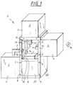
- the measuring device shown in Figure 1 is designed such that the measuring units (2, 3) in at least two different positions can be rigidly attached to a base frame (side parts 15, cover plates 23, base plate 8) of the measuring device.
- the base frame of the measuring device has, inter alia, two essentially opposite side parts (15) with a rectangular shape, to which the measuring units (2, 3) are rigidly attached.
- a plurality of holes (14) only partially shown here are provided in the side parts, through which the measuring units (2, 3) can be rigidly connected to the side parts (15) by means of screws (6).
- the holes of this special embodiment are each provided in the side parts (15) in such a way that they are equally spaced in pairs exhibit. Holes are also correspondingly provided in the side walls of the containers (4) of the measuring units (2, 3), so that the containers can be fastened in their optimal position using screws and nuts on the side parts (15).
- one of the two measuring units (2) or an additional measuring unit (2) can, for example, be mounted in the still free holes (14) in the side part (15).
- the base frame of the measuring device also has the cover plates (23) which are fastened to the side parts (15) by means of fastening devices (not shown here), such as screws.
- a base plate (8) which is designed here as a block on which a workpiece holder (1) is attached. This is used to hold the workpiece to be measured.
- the workpiece holder is designed as a flat plate on which the workpiece to be measured can be arranged.
- the workpiece holder (1) can also be designed differently.
- a clamping device can also be provided on the plate shown here, by means of which, for example, the workpiece to be measured can be clamped.
- the measuring units (2, 3) are also only shown schematically for the sake of simplicity. They comprise containers (4) which serve to encapsulate the measuring units (2, 3) and measuring arms (7), at the tip of which there is a probe (17) with which a workpiece to be measured can be measured.
- the measuring arms (7) are connected in the containers (4) with a corresponding mechanism so that the measuring arms (7) can be moved in three mutually perpendicular directions x, y and z (see arrow 16).
- the construction of such a mechanism can be carried out as described above in connection with the portal measuring devices or the stator measuring devices.
- the workpiece to be measured can be measured by placing the tips of the probes (17) at the corresponding points on the probe the workpiece to be measured and for this purpose the deflection in the different axes x, y and z is measured with respect to a reference point.
- Measuring units of the type mentioned have been known for some time and are manufactured, for example, by the Carl Zeiss company, so that a more detailed description of the measuring units (2, 3) with the associated mechanics and electronics is dispensed with.
- FIG. 2 shows a development of the measuring device according to FIG. 1, which represents a particularly advantageous embodiment of the invention.
- a base frame is also provided, in which measuring units (2) can be attached to at least two positions on two essentially opposite side parts (18) which have a curved shape.
- the side parts (18) are designed in the form of a ring for the exemplary embodiment shown here and are provided with a multiplicity of holes (14) which are all at the same distance from one another.
- the measuring units (2) which are constructed analogously to the measuring units (2) of FIG. 1, are rigidly fastened to the side parts (18) by means of screws (6) and associated nuts (not shown in more detail here) .
- a base plate (8) which is also rigidly connected to the side parts (18) by means of screws (6).
- a workpiece carrier (1) On the base plate (8) there is a workpiece carrier (1), which is not described here in greater detail and on which there is, for example, an engine block (9) with V-shaped cylinders.
- an engine block (9) with V-shaped cylinders For better understanding, two of the cylinders are drawn in elevation to show how the tips of the probes scan the holes in the cylinders.
- the measuring device shown in FIG. 2 has the advantage over the measuring device shown in FIG. 1 that the measuring arms (7) and thus the probe heads (17) can not only be arranged perpendicularly or parallel to the base plate (8), but also in Areas between these two Positions. As can be seen in FIG. 2, this makes it easy to measure, for example, bores with simple probes, for which special, complex probes would be required with a measuring arm (7) lying perpendicular or parallel to the base plate (8).
- the setting of the angle at which the measuring arm (7) is relative to the base plate (8) can be set even more finely if additional pairs of holes are provided in the side parts (18) with the defined distance. For small areas, the said angle can be adjusted particularly finely if the corresponding bores (14) are provided in the form of elongated holes, so that the measuring units (2) can be finely adjusted in these elongated holes.
- Figure 3 shows a second embodiment of a measuring device according to the invention.
- the measuring unit (19) shown here is movably attached to the base frame (base plate 8, side parts 20) via guides (13a, 13b, 13c) of the side parts (20).
- the guides (13b, 13c) have a curved shape so that when the container (12) is moved along the guides (13b, 13c) the angle of the measuring arm (7) and the probe (17) relative to the base plate (8 ) changes continuously.
- the container (12) In order to be able to move the container (12) of the measuring unit (19) over the guides (13a, 13b, 13c), the container (12) has rubber-coated rollers, not shown here, which run on the guides (13a, 13b) and to move the measuring unit (19) via a correspondingly provided in the measuring unit (19) stepper motor. In order to ensure a secure hold of the container (12), free-running rollers are additionally provided on the guides (13c), which are pressed against the guides (13c) and thus ensure the adhesion of the rubber-coated rollers on the guides (13b).
- a clamping device is provided in the measuring unit (19) with which the measuring unit (19) can be temporarily rigidly connected to the guides (13c) and thus of course also to the base frame (base plate 8, side parts 20).
- a clamping device is here in the form of two rubber blocks (22) provided, which are each pressed electronically controlled on the guides (13c) of the side parts (20), so that the measuring unit (19) due to the adhesive force rigid with the guides (13c) and thus with the base frame (base plate 8, side parts 20) connected is.
- the measuring device shown in FIG. 3 is relatively expensive compared to the measuring devices according to FIGS. 1 and 2, it nevertheless has the particular advantage that the angle of the measuring arm (7) and the probe (17) relative to the base plate (8) is very fine and can also be set very quickly via an appropriate electronic control system, so that the measuring device shown in FIG. 3 is flexible with regard to the measurement of different workpieces with different geometries. As a result, the measuring device shown is particularly suitable for use in test lanes in which the geometry of the workpieces to be measured frequently changes.
- the measuring unit can also be movably attached to the base frame by being attached to a lifting device that can lift the measuring unit.
- the lifting device should additionally have a tilting device with which the measuring unit can be tilted in at least one direction.
- it can be provided in the form of a hydraulically controlled lifting platform, a tilting plate being additionally provided on the lifting platform, which is also tilted by means of a hydraulic system.
- the measuring unit is mounted on the tiltable plate.
- the measuring unit does not have to be designed such that the measuring arm can be moved with the probe in three perpendicular directions x, y and z, as described above, but it is also possible, for example, to provide measuring units in which the probe is only in one or two directions is movable.
- the tool carriers shown can of course also be designed according to the requirements, and for example in the form of a turntable or in the form of a pallet system.
- the base frame does not have to consist of a base plate with side parts, as shown throughout, but can of course also be constructed differently.
- the probes do not have to be designed as touching probes as shown, but can also be provided as optical probes, for example.
- the measuring devices (2) and (3) can be brought into different positions such that the angle between the longitudinal axis of the relevant measuring arms (7) and a horizontal plane, the orientation of which is defined by the surface on which the base frame is placed is different in the different positions.
Landscapes
- Physics & Mathematics (AREA)
- General Physics & Mathematics (AREA)
- Length Measuring Devices With Unspecified Measuring Means (AREA)
- A Measuring Device Byusing Mechanical Method (AREA)
Applications Claiming Priority (2)
| Application Number | Priority Date | Filing Date | Title |
|---|---|---|---|
| DE19614747 | 1996-04-15 | ||
| DE19614747 | 1996-04-15 |
Publications (3)
| Publication Number | Publication Date |
|---|---|
| EP0802393A2 true EP0802393A2 (fr) | 1997-10-22 |
| EP0802393A3 EP0802393A3 (fr) | 1998-04-15 |
| EP0802393B1 EP0802393B1 (fr) | 2002-06-19 |
Family
ID=7791264
Family Applications (1)
| Application Number | Title | Priority Date | Filing Date |
|---|---|---|---|
| EP97105826A Expired - Lifetime EP0802393B1 (fr) | 1996-04-15 | 1997-04-09 | Dispositif de mesure pour arpenter des pièces à usiner |
Country Status (3)
| Country | Link |
|---|---|
| US (2) | US5901455A (fr) |
| EP (1) | EP0802393B1 (fr) |
| DE (2) | DE19703690A1 (fr) |
Cited By (1)
| Publication number | Priority date | Publication date | Assignee | Title |
|---|---|---|---|---|
| EP2434253B1 (fr) | 2010-09-27 | 2018-01-24 | Mitutoyo Corporation | Tête de mesure de coordonnées et machine de mesure de coordonnées |
Families Citing this family (16)
| Publication number | Priority date | Publication date | Assignee | Title |
|---|---|---|---|---|
| KR100355558B1 (ko) * | 1997-06-16 | 2002-12-26 | 한국전기초자 주식회사 | 음극선관용펀넬결합체의검사장치및검사방법 |
| DE29907056U1 (de) | 1999-04-21 | 1999-07-15 | Gebrüder Demes GmbH, 48703 Stadtlohn | Palettenmeßvorrichtung |
| US6298572B1 (en) | 2000-01-10 | 2001-10-09 | Mcauley Brian | Universal holding device for effectuating three dimensional measurement of a part and method of constructing such a holding device |
| JP3647378B2 (ja) * | 2001-03-02 | 2005-05-11 | キヤノン株式会社 | マルチプローブを用いた形状測定装置及び測定方法 |
| DE10200776A1 (de) * | 2002-01-10 | 2003-07-24 | Zf Lemfoerder Metallwaren Ag | Rissprüfanlage zum Überprüfen von Teilen |
| EP1443301B1 (fr) * | 2003-01-29 | 2010-02-10 | Tesa SA | Palpeur orientable |
| EP1443300B1 (fr) * | 2003-01-29 | 2010-02-24 | Tesa SA | Palpeur orientable |
| DE102004020996A1 (de) * | 2004-04-19 | 2005-11-03 | Carl Zeiss Industrielle Messtechnik Gmbh | Koordinatenmessgerät zum messtechnischen Bestimmen einer Koordinate an einem Messobjekt |
| US8448346B2 (en) * | 2010-10-06 | 2013-05-28 | United Fastener & Supply LLC | Trigger assembly for parts checking jigs and the like |
| DE102013204333A1 (de) * | 2013-03-13 | 2014-09-18 | Krones Ag | Vorrichtung und Verfahren zum Überprüfen der Etikettiergenauigkeit an Behältern |
| DE102013205889B3 (de) | 2013-04-03 | 2014-05-28 | Kennametal Inc. | Kupplungsteil, insbesondere Schneidkopf für ein Rotationswerkzeug sowie ein derartiges Rotationswerkzeug |
| WO2015147910A1 (fr) * | 2014-03-24 | 2015-10-01 | Marposs Corporation | Appareil d'inspection d'alésages usinés |
| US9581424B2 (en) * | 2014-12-09 | 2017-02-28 | Tokyo Seimitsu Co., Ltd. | Roundness measuring apparatus |
| CN112077370B (zh) | 2019-06-13 | 2024-10-01 | 肯纳金属印度有限公司 | 可转位钻头刀片 |
| CN110388866A (zh) * | 2019-08-02 | 2019-10-29 | 云南华联锌铟股份有限公司 | 一种破碎机排矿口测量装置 |
| CN115703157A (zh) | 2021-08-17 | 2023-02-17 | 肯纳金属印度有限公司 | 具有冷却剂系统的可转位钻头组件 |
Family Cites Families (10)
| Publication number | Priority date | Publication date | Assignee | Title |
|---|---|---|---|---|
| DE2952497C2 (de) * | 1979-08-13 | 1982-08-26 | Maag-Zahnräder & -Maschinen AG, 8023 Zürich | Zahnflankenprüfgerät |
| IT1190574B (it) * | 1986-05-27 | 1988-02-16 | Dea Spa | Macchina di misura a coordinate |
| DE3714862A1 (de) * | 1987-05-05 | 1988-11-17 | Mauser Werke Oberndorf | Flexible cnc-vielstellenmesseinrichtung |
| FR2617600B1 (fr) * | 1987-06-30 | 1989-12-08 | Inst Francais Du Petrole | Dispositif et methode de mesure des deformations d'un echantillon |
| JPH0683957B2 (ja) * | 1988-11-10 | 1994-10-26 | 信越半導体株式会社 | 円筒研磨装置 |
| IT1232879B (it) * | 1989-07-21 | 1992-03-05 | Prima Ind Spa | Dispositivo e metodo per la misurazione automatica delle dimensioni di solidi di rivoluzione |
| JP2945090B2 (ja) * | 1990-07-09 | 1999-09-06 | キヤノン株式会社 | エンコーダ |
| JP2743212B2 (ja) * | 1990-07-23 | 1998-04-22 | 株式会社山形信越石英 | 石英治具の測定装置 |
| US5337485A (en) * | 1992-01-28 | 1994-08-16 | Chien An Y | Roundness error and crown electronic measuring system |
| JPH07112366A (ja) * | 1993-10-15 | 1995-05-02 | Koyo Seiko Co Ltd | 工作機械 |
-
1997
- 1997-01-31 DE DE19703690A patent/DE19703690A1/de not_active Withdrawn
- 1997-04-09 EP EP97105826A patent/EP0802393B1/fr not_active Expired - Lifetime
- 1997-04-09 DE DE59707541T patent/DE59707541D1/de not_active Expired - Lifetime
- 1997-04-11 US US08/833,989 patent/US5901455A/en not_active Ceased
-
2000
- 2000-01-25 US US09/496,033 patent/USRE37695E1/en not_active Expired - Lifetime
Cited By (1)
| Publication number | Priority date | Publication date | Assignee | Title |
|---|---|---|---|---|
| EP2434253B1 (fr) | 2010-09-27 | 2018-01-24 | Mitutoyo Corporation | Tête de mesure de coordonnées et machine de mesure de coordonnées |
Also Published As
| Publication number | Publication date |
|---|---|
| DE59707541D1 (de) | 2002-07-25 |
| US5901455A (en) | 1999-05-11 |
| DE19703690A1 (de) | 1997-10-16 |
| EP0802393A3 (fr) | 1998-04-15 |
| USRE37695E1 (en) | 2002-05-14 |
| EP0802393B1 (fr) | 2002-06-19 |
Similar Documents
| Publication | Publication Date | Title |
|---|---|---|
| EP0802393A2 (fr) | Dispositif de mesure pour arpenter des pièces à usiner | |
| DE69306088T2 (de) | Portale Fräs- und Bohrmaschine | |
| DE3878225T2 (de) | Geraet zum nachpruefen von werkstueckabmessungen. | |
| DE4109866A1 (de) | Reparaturstand mit richtrahmen | |
| EP0499943A2 (fr) | Dispositif pour la mise en oeuvre d'éssais par contraintes en flexion alternées à 4 points d'appui | |
| DE102013102564A1 (de) | Traverseneinheit für eine Prüfvorrichtung für Leiterplatten, sowie Prüfvorrichtung damit | |
| DE3243275C2 (de) | Meßgerät | |
| EP1955009B1 (fr) | Dispositif de détermination d'une grandeur de mesure sur un objet à mesurer | |
| EP1108974B1 (fr) | Appareil de mesure de coordonnées | |
| DE2239553B2 (de) | Zug- und/oder druckpruefmaschine | |
| DE2726867C2 (de) | Halterung für ein Meß- und/oder Prüfgerät | |
| DE2132021B2 (de) | Vorrichtung, vorzugsweise Richtvorrichtung zum Ausführen der Operationen für das Ausbessern und Zurückverformen bzw. Zurückführen auf die ursprüngliche Form von z.B. verbeulten oder beschädigten Blechen von Karosserien, insbesondere von Kraftfahrzeugen | |
| DE2530644C2 (de) | Gleitführung für Teile eines Teleskop-Kranauslegers | |
| WO2024068449A1 (fr) | Dispositif de mesure ou de traitement d'objets, procédé de fonctionnement | |
| DE69408371T2 (de) | Vorrichtung zum Heben von Fässern oder gleichartigen Gegenständen | |
| EP1521054B1 (fr) | Dispositif pour maintenir une pièce de carrosserie dans une position de mesure | |
| EP3500398B1 (fr) | Dispositif d'accueil destiné à accueillir un objet de forme quelconque | |
| DE102020007732A1 (de) | Befestigungsvorrichtung zur Befestigung eines elektrischen Energiespeichers für ein Fahrzeug an einem Trägerschlitten | |
| DE29904767U1 (de) | Koordinatenmeßgerät mit einem biegesteifen Meßtisch | |
| DE20204832U1 (de) | Einrichtung zur Messung der Grob- und/oder Feinstruktur einer Oberfläche eines Werkstücks | |
| EP2006634B1 (fr) | Dispositif de fixation pour composants de mesure, en particulier composants en tôle d'une carrosserie de véhicule, dans une position de référence | |
| DE20008723U1 (de) | Vorrichtung zum Führen eines Tisches in der X-Y-Ebene | |
| DE19727754A1 (de) | Vorrichtung zum Einspannen und Prüfen von Prüfkörpern | |
| EP0212448A2 (fr) | Dispositif pour décomposer des forces vectorielles | |
| DE3703260A1 (de) | Vorrichtung zum pruefen der achslager von fahrzeugraedern |
Legal Events
| Date | Code | Title | Description |
|---|---|---|---|
| PUAI | Public reference made under article 153(3) epc to a published international application that has entered the european phase |
Free format text: ORIGINAL CODE: 0009012 |
|
| AK | Designated contracting states |
Kind code of ref document: A2 Designated state(s): DE FR GB IT |
|
| PUAL | Search report despatched |
Free format text: ORIGINAL CODE: 0009013 |
|
| AK | Designated contracting states |
Kind code of ref document: A3 Designated state(s): DE FR GB IT |
|
| 17P | Request for examination filed |
Effective date: 19980918 |
|
| 17Q | First examination report despatched |
Effective date: 20000314 |
|
| RAP1 | Party data changed (applicant data changed or rights of an application transferred) |
Owner name: CARL-ZEISS-STIFTUNG TRADING AS CARL ZEISS Owner name: CARL ZEISS |
|
| RTI1 | Title (correction) |
Free format text: MEASURING DEVICE FOR MEASURING THE DIMENSIONS OF WORKPIECES |
|
| GRAG | Despatch of communication of intention to grant |
Free format text: ORIGINAL CODE: EPIDOS AGRA |
|
| GRAG | Despatch of communication of intention to grant |
Free format text: ORIGINAL CODE: EPIDOS AGRA |
|
| GRAH | Despatch of communication of intention to grant a patent |
Free format text: ORIGINAL CODE: EPIDOS IGRA |
|
| GRAH | Despatch of communication of intention to grant a patent |
Free format text: ORIGINAL CODE: EPIDOS IGRA |
|
| GRAA | (expected) grant |
Free format text: ORIGINAL CODE: 0009210 |
|
| AK | Designated contracting states |
Kind code of ref document: B1 Designated state(s): DE FR GB IT |
|
| REG | Reference to a national code |
Ref country code: GB Ref legal event code: FG4D Free format text: NOT ENGLISH |
|
| REF | Corresponds to: |
Ref document number: 59707541 Country of ref document: DE Date of ref document: 20020725 |
|
| GBT | Gb: translation of ep patent filed (gb section 77(6)(a)/1977) |
Effective date: 20020801 |
|
| ET | Fr: translation filed | ||
| PLBE | No opposition filed within time limit |
Free format text: ORIGINAL CODE: 0009261 |
|
| STAA | Information on the status of an ep patent application or granted ep patent |
Free format text: STATUS: NO OPPOSITION FILED WITHIN TIME LIMIT |
|
| 26N | No opposition filed |
Effective date: 20030320 |
|
| REG | Reference to a national code |
Ref country code: GB Ref legal event code: 732E |
|
| REG | Reference to a national code |
Ref country code: FR Ref legal event code: TP |
|
| PGFP | Annual fee paid to national office [announced via postgrant information from national office to epo] |
Ref country code: GB Payment date: 20140422 Year of fee payment: 18 |
|
| PGFP | Annual fee paid to national office [announced via postgrant information from national office to epo] |
Ref country code: IT Payment date: 20140430 Year of fee payment: 18 Ref country code: FR Payment date: 20140422 Year of fee payment: 18 Ref country code: DE Payment date: 20140418 Year of fee payment: 18 |
|
| REG | Reference to a national code |
Ref country code: DE Ref legal event code: R119 Ref document number: 59707541 Country of ref document: DE |
|
| GBPC | Gb: european patent ceased through non-payment of renewal fee |
Effective date: 20150409 |
|
| PG25 | Lapsed in a contracting state [announced via postgrant information from national office to epo] |
Ref country code: GB Free format text: LAPSE BECAUSE OF NON-PAYMENT OF DUE FEES Effective date: 20150409 Ref country code: DE Free format text: LAPSE BECAUSE OF NON-PAYMENT OF DUE FEES Effective date: 20151103 Ref country code: IT Free format text: LAPSE BECAUSE OF NON-PAYMENT OF DUE FEES Effective date: 20150409 |
|
| REG | Reference to a national code |
Ref country code: FR Ref legal event code: ST Effective date: 20151231 |
|
| PG25 | Lapsed in a contracting state [announced via postgrant information from national office to epo] |
Ref country code: FR Free format text: LAPSE BECAUSE OF NON-PAYMENT OF DUE FEES Effective date: 20150430 |