EP0802393A2 - Measuring device for measuring the dimension of workpieces - Google Patents
Measuring device for measuring the dimension of workpieces Download PDFInfo
- Publication number
- EP0802393A2 EP0802393A2 EP97105826A EP97105826A EP0802393A2 EP 0802393 A2 EP0802393 A2 EP 0802393A2 EP 97105826 A EP97105826 A EP 97105826A EP 97105826 A EP97105826 A EP 97105826A EP 0802393 A2 EP0802393 A2 EP 0802393A2
- Authority
- EP
- European Patent Office
- Prior art keywords
- measuring
- measuring device
- measuring unit
- workpiece
- base frame
- Prior art date
- Legal status (The legal status is an assumption and is not a legal conclusion. Google has not performed a legal analysis and makes no representation as to the accuracy of the status listed.)
- Granted
Links
Images


Classifications
-
- G—PHYSICS
- G01—MEASURING; TESTING
- G01B—MEASURING LENGTH, THICKNESS OR SIMILAR LINEAR DIMENSIONS; MEASURING ANGLES; MEASURING AREAS; MEASURING IRREGULARITIES OF SURFACES OR CONTOURS
- G01B5/00—Measuring arrangements characterised by the use of mechanical techniques
- G01B5/004—Measuring arrangements characterised by the use of mechanical techniques for measuring coordinates of points
Definitions
- the invention relates to a measuring device for measuring workpieces, comprising a base frame with a workpiece holder for receiving a workpiece to be measured and at least one measuring unit for measuring the workpiece.
- portal measuring devices that are usually constructed as follows. They comprise a base frame in the form of a base plate on which a workpiece holder is attached. A workpiece to be measured can be attached to the base plate via this. A portal measuring unit is attached to the base plate to measure the workpiece.
- This comprises two guides fastened to the side of the base plate, on which a portal is guided that completely spans the base plate. The portal can be moved along the base plate via the guides. The spanning part of the portal in turn has guides on which a slide can be moved across the base plate.
- guides are provided in the carriage, via which a measuring arm with an attached probe can be moved up and down. The probe can thus be moved in three mutually perpendicular directions using the described mechanism of the portal measuring unit.
- a workpiece to be measured can be measured in the x, y and z directions via the position of the probe.
- stand measuring devices are also known from the prior art.
- the stand measuring devices differ from the portal measuring devices essentially only in the design of the measuring unit.
- the measuring unit here has a stand which is on one side of the base frame attached guide runs so that the stand can be moved along the base plate.
- the stand itself is provided with guides so that a carriage can be moved up and down.
- the carriage in turn has guides by means of which a horizontally lying measuring arm with a probe attached to it can be moved transversely to the base plate. Workpieces can also be measured in three mutually perpendicular directions x, y and z using said stand measuring device.
- the object of the present invention is therefore to further develop the known measuring devices in such a way that the measurement of different workpieces with different geometries is simplified with one and the same measuring device.
- the measuring unit for measuring a workpiece can be brought into at least two different positions. This results in the particular advantages that the measuring unit can be arranged in accordance with the workpiece to be measured so that the points to be measured on the workpiece are as possible are easy to reach with the probe.
- two or more measuring units can be fitted in the measuring device as required, so that on the one hand each of the measuring units can optimally measure certain areas of the workpiece to be measured and on the other hand the total time for measuring the workpiece is reduced, since two or more measuring units measure simultaneously.
- the measuring unit can be rigidly attached to the base frame in at least two different positions. To change the position, the rigid connection has to be loosened and the measuring unit has to be rigidly fastened in another position.
- the rigid connection between the measuring units and the base frame can be established by fastening the measuring unit to at least a part of the base frame which fixes the measuring unit in position.
- the part fixing the measuring unit can have a wide variety of embodiments and can be provided, for example, in the form of side parts which are arranged on the side of the measuring unit.
- the measuring unit can be rigidly connected to the side parts via fastening means, such as screws.
- the side parts can also be provided in the form of narrow contact surfaces running at the edge of the measuring units, on which the measuring units rest and with which the measuring units are screwed.
- the measuring unit is movably attached to the base frame of the measuring device.
- the base frame here has special devices by means of which the measuring units can be moved into at least two different positions. These devices can, for example, be guides along which the measuring unit can be moved.
- the guides can either be straight or have a curved shape.
- a hydraulic lifting device can also be used, for example, which raises or lowers the measuring unit and which advantageously also has a hydraulically controlled mechanism for tilting the measuring unit in at least one direction.
- FIGS. 1-3 are merely schematic diagrams which are not to scale and in which details which are largely insignificant to the invention have been omitted.
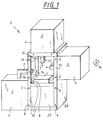
- the measuring device shown in Figure 1 is designed such that the measuring units (2, 3) in at least two different positions can be rigidly attached to a base frame (side parts 15, cover plates 23, base plate 8) of the measuring device.
- the base frame of the measuring device has, inter alia, two essentially opposite side parts (15) with a rectangular shape, to which the measuring units (2, 3) are rigidly attached.
- a plurality of holes (14) only partially shown here are provided in the side parts, through which the measuring units (2, 3) can be rigidly connected to the side parts (15) by means of screws (6).
- the holes of this special embodiment are each provided in the side parts (15) in such a way that they are equally spaced in pairs exhibit. Holes are also correspondingly provided in the side walls of the containers (4) of the measuring units (2, 3), so that the containers can be fastened in their optimal position using screws and nuts on the side parts (15).
- one of the two measuring units (2) or an additional measuring unit (2) can, for example, be mounted in the still free holes (14) in the side part (15).
- the base frame of the measuring device also has the cover plates (23) which are fastened to the side parts (15) by means of fastening devices (not shown here), such as screws.
- a base plate (8) which is designed here as a block on which a workpiece holder (1) is attached. This is used to hold the workpiece to be measured.
- the workpiece holder is designed as a flat plate on which the workpiece to be measured can be arranged.
- the workpiece holder (1) can also be designed differently.
- a clamping device can also be provided on the plate shown here, by means of which, for example, the workpiece to be measured can be clamped.
- the measuring units (2, 3) are also only shown schematically for the sake of simplicity. They comprise containers (4) which serve to encapsulate the measuring units (2, 3) and measuring arms (7), at the tip of which there is a probe (17) with which a workpiece to be measured can be measured.
- the measuring arms (7) are connected in the containers (4) with a corresponding mechanism so that the measuring arms (7) can be moved in three mutually perpendicular directions x, y and z (see arrow 16).
- the construction of such a mechanism can be carried out as described above in connection with the portal measuring devices or the stator measuring devices.
- the workpiece to be measured can be measured by placing the tips of the probes (17) at the corresponding points on the probe the workpiece to be measured and for this purpose the deflection in the different axes x, y and z is measured with respect to a reference point.
- Measuring units of the type mentioned have been known for some time and are manufactured, for example, by the Carl Zeiss company, so that a more detailed description of the measuring units (2, 3) with the associated mechanics and electronics is dispensed with.
- FIG. 2 shows a development of the measuring device according to FIG. 1, which represents a particularly advantageous embodiment of the invention.
- a base frame is also provided, in which measuring units (2) can be attached to at least two positions on two essentially opposite side parts (18) which have a curved shape.
- the side parts (18) are designed in the form of a ring for the exemplary embodiment shown here and are provided with a multiplicity of holes (14) which are all at the same distance from one another.
- the measuring units (2) which are constructed analogously to the measuring units (2) of FIG. 1, are rigidly fastened to the side parts (18) by means of screws (6) and associated nuts (not shown in more detail here) .
- a base plate (8) which is also rigidly connected to the side parts (18) by means of screws (6).
- a workpiece carrier (1) On the base plate (8) there is a workpiece carrier (1), which is not described here in greater detail and on which there is, for example, an engine block (9) with V-shaped cylinders.
- an engine block (9) with V-shaped cylinders For better understanding, two of the cylinders are drawn in elevation to show how the tips of the probes scan the holes in the cylinders.
- the measuring device shown in FIG. 2 has the advantage over the measuring device shown in FIG. 1 that the measuring arms (7) and thus the probe heads (17) can not only be arranged perpendicularly or parallel to the base plate (8), but also in Areas between these two Positions. As can be seen in FIG. 2, this makes it easy to measure, for example, bores with simple probes, for which special, complex probes would be required with a measuring arm (7) lying perpendicular or parallel to the base plate (8).
- the setting of the angle at which the measuring arm (7) is relative to the base plate (8) can be set even more finely if additional pairs of holes are provided in the side parts (18) with the defined distance. For small areas, the said angle can be adjusted particularly finely if the corresponding bores (14) are provided in the form of elongated holes, so that the measuring units (2) can be finely adjusted in these elongated holes.
- Figure 3 shows a second embodiment of a measuring device according to the invention.
- the measuring unit (19) shown here is movably attached to the base frame (base plate 8, side parts 20) via guides (13a, 13b, 13c) of the side parts (20).
- the guides (13b, 13c) have a curved shape so that when the container (12) is moved along the guides (13b, 13c) the angle of the measuring arm (7) and the probe (17) relative to the base plate (8 ) changes continuously.
- the container (12) In order to be able to move the container (12) of the measuring unit (19) over the guides (13a, 13b, 13c), the container (12) has rubber-coated rollers, not shown here, which run on the guides (13a, 13b) and to move the measuring unit (19) via a correspondingly provided in the measuring unit (19) stepper motor. In order to ensure a secure hold of the container (12), free-running rollers are additionally provided on the guides (13c), which are pressed against the guides (13c) and thus ensure the adhesion of the rubber-coated rollers on the guides (13b).
- a clamping device is provided in the measuring unit (19) with which the measuring unit (19) can be temporarily rigidly connected to the guides (13c) and thus of course also to the base frame (base plate 8, side parts 20).
- a clamping device is here in the form of two rubber blocks (22) provided, which are each pressed electronically controlled on the guides (13c) of the side parts (20), so that the measuring unit (19) due to the adhesive force rigid with the guides (13c) and thus with the base frame (base plate 8, side parts 20) connected is.
- the measuring device shown in FIG. 3 is relatively expensive compared to the measuring devices according to FIGS. 1 and 2, it nevertheless has the particular advantage that the angle of the measuring arm (7) and the probe (17) relative to the base plate (8) is very fine and can also be set very quickly via an appropriate electronic control system, so that the measuring device shown in FIG. 3 is flexible with regard to the measurement of different workpieces with different geometries. As a result, the measuring device shown is particularly suitable for use in test lanes in which the geometry of the workpieces to be measured frequently changes.
- the measuring unit can also be movably attached to the base frame by being attached to a lifting device that can lift the measuring unit.
- the lifting device should additionally have a tilting device with which the measuring unit can be tilted in at least one direction.
- it can be provided in the form of a hydraulically controlled lifting platform, a tilting plate being additionally provided on the lifting platform, which is also tilted by means of a hydraulic system.
- the measuring unit is mounted on the tiltable plate.
- the measuring unit does not have to be designed such that the measuring arm can be moved with the probe in three perpendicular directions x, y and z, as described above, but it is also possible, for example, to provide measuring units in which the probe is only in one or two directions is movable.
- the tool carriers shown can of course also be designed according to the requirements, and for example in the form of a turntable or in the form of a pallet system.
- the base frame does not have to consist of a base plate with side parts, as shown throughout, but can of course also be constructed differently.
- the probes do not have to be designed as touching probes as shown, but can also be provided as optical probes, for example.
- the measuring devices (2) and (3) can be brought into different positions such that the angle between the longitudinal axis of the relevant measuring arms (7) and a horizontal plane, the orientation of which is defined by the surface on which the base frame is placed is different in the different positions.
Landscapes
- Physics & Mathematics (AREA)
- General Physics & Mathematics (AREA)
- Length Measuring Devices With Unspecified Measuring Means (AREA)
- A Measuring Device Byusing Mechanical Method (AREA)
Abstract
Es wird eine Meßeinrichtung zur Vermessung von Werkstücken beschrieben, die ein Grundgestell mit einem Werkstückaufnehmer zur Aufnahme eines zu vermessenden Werkstückes und wenigstens eine Meßeinheit zur Vermessung des Werkstückes umfaßt. Um die Meßeinrichtung möglichst flexibel auszugestalten und auf möglichst einfache Weise die Vermessung von unterschiedlichen Werkstücken zu gestatten, wird vorgeschlagen, daß die Meßeinheit in wenigstens zwei unterschiedliche Positionen bringbar ist.
Description
Die Erfindung betrifft eine Meßeinrichtung zur Vermessung von Werkstücken, umfassend ein Grundgestell mit einem Werkstückaufnehmer zur Aufnahme eines zu vermessenden Werkstücks und wenigstens eine Meßeinheit zur Vermessung des Werkstückes.The invention relates to a measuring device for measuring workpieces, comprising a base frame with a workpiece holder for receiving a workpiece to be measured and at least one measuring unit for measuring the workpiece.
Derartige Meßeinrichtungen sind aus dem Stand der Technik bereits hinreichend bekannt. So gibt es beispielsweise sogenannte Portalmeßeinrichtungen die üblicherweise wie folgt aufgebaut sind. Sie umfassen ein Grundgestell in Form einer Grundplatte, auf der ein Werkstückaufnehmer befestigt ist. Über diesen kann ein zu vermessendes Werkstück auf der Grundplatte befestigt werden. Zur Vermessung des Werkstückes ist an der Grundplatte eine Portalmeßeinheit befestigt. Diese umfaßt zwei seitlich der Grundplatte befestigte Führungen, auf denen ein Portal geführt wird, das die Grundplatte komplett überspannt.Das Portal kann über die Führungen längs der Grundplatte bewegt werden. Der überspannende Teil des Portals weist seinerseits auf Führungen auf, auf denen ein Schlitten quer zur Grundplatte bewegt werden kann. Zusätzlich sind im Schlitten seinerseits Führungen vorgesehen, über die ein Meßarm mit einem daran befindlichen Tastkopf auf und ab bewegt werden kann. Über die beschriebene Mechanik der Portalmeßeinheit kann somit der Tastkopf in drei aufeinander senkrecht stehenden Richtungen bewegt werden. Über die Position des Tastkopfes kann ein zu vermessendes Werkstück in x-, y- und z-Richtung vermessen.Such measuring devices are already well known from the prior art. For example, there are so-called portal measuring devices that are usually constructed as follows. They comprise a base frame in the form of a base plate on which a workpiece holder is attached. A workpiece to be measured can be attached to the base plate via this. A portal measuring unit is attached to the base plate to measure the workpiece. This comprises two guides fastened to the side of the base plate, on which a portal is guided that completely spans the base plate. The portal can be moved along the base plate via the guides. The spanning part of the portal in turn has guides on which a slide can be moved across the base plate. In addition, guides are provided in the carriage, via which a measuring arm with an attached probe can be moved up and down. The probe can thus be moved in three mutually perpendicular directions using the described mechanism of the portal measuring unit. A workpiece to be measured can be measured in the x, y and z directions via the position of the probe.
Desweiteren sind aus dem Stand der Technik auch sogenannte Ständermeßeinrichtungen bekannt. Die Ständermeßeinrichtungen unterscheiden sich gegenüber den Portalmeßeinrichtungen im wesentlichen lediglich in der Ausführung der Meßeinheit. Im Gegensatz zur Portalmeßeinrichtung weist die Meßeinheit hier einen Ständer auf, der auf einer seitlich des Grundgestelles befestigten Führung läuft, so daß der Ständer längs der Grundplatte bewegt werden kann. Der Ständer seinerseits ist mit Führungen versehen, so daß hieran ein Schlitten auf und ab bewegt werden kann. Der Schlitten wiederum verfügt über Führungen, über die ein horizontal liegender Meßarm mit einem daran befestigten Tastkopf quer zur Grundplatte bewegt werden kann. Mit der besagten Ständermeßeinrichtung lassen sich ebenfalls Werkstücke in drei aufeinander senkrecht stehenden Richtungen x, y und z vermessen.Furthermore, so-called stand measuring devices are also known from the prior art. The stand measuring devices differ from the portal measuring devices essentially only in the design of the measuring unit. In contrast to the portal measuring device, the measuring unit here has a stand which is on one side of the base frame attached guide runs so that the stand can be moved along the base plate. The stand itself is provided with guides so that a carriage can be moved up and down. The carriage in turn has guides by means of which a horizontally lying measuring arm with a probe attached to it can be moved transversely to the base plate. Workpieces can also be measured in three mutually perpendicular directions x, y and z using said stand measuring device.
Die Besonderheit der aus dem Stand der Technik bekannten Meßeinrichtungen ist darin zu sehen, daß die Meßeinheiten starr in ihrer Position befestigt sind. Portalmeßeinrichtungen beispielsweise, deren Meßarm senkrecht zur Grundplatte steht und damit auf das zu vermessende Werkstück abgesenkt wird, können deshalb nur unter Verwendung von relativ aufwendigen Tastköpfen schwer zu erreichende Meßpunkte, wie beispielsweise seitliche Bohrungen eines Werkstückes vermessen. Insbesondere ergeben sich Probleme, wenn mit ein und derselben Meßeinrichtung häufig verschiedene Werkstücke mit unterschiedlicher Geometrie vermessen werden, da hierfür oftmals viele spezielle Tastköpfe vorgesehen werden müssen.The peculiarity of the measuring devices known from the prior art can be seen in the fact that the measuring units are rigidly fixed in their position. Portal measuring devices, for example, whose measuring arm is perpendicular to the base plate and thus lowered onto the workpiece to be measured, can therefore only measure measuring points that are difficult to reach, such as lateral bores of a workpiece, using relatively complex probe heads. Problems arise in particular when different workpieces with different geometries are frequently measured with one and the same measuring device, since many special probes often have to be provided for this.
Die Aufgabe der vorliegenden Erfindung ist es deshalb die bekannten Meßeinrichtungen derart weiterzubilden, daß hierdurch die Vermessung von verschiedenen Werkstücken mit unterschiedlicher Geometrie mit ein und derselben Meßeinrichtung vereinfacht wird.The object of the present invention is therefore to further develop the known measuring devices in such a way that the measurement of different workpieces with different geometries is simplified with one and the same measuring device.
Die Aufgabe wird gemäß den Merkmalen des kennzeichnenden Teils des Anspruches 1 gelöst.The object is achieved according to the features of the characterizing part of
Der Grundgedanke der Erfindung ist darin zu sehen, daß die Meßeinheit zur Vermessung eines Werkstückes in wenigstens zwei unterschiedliche Positionen gebracht werden kann. Hieraus ergeben sich die besonderen Vorteile, daß die Meßeinheit entsprechend dem zu vermessenden Werkstück so angeordnet werden kann, daß die am Werkstück zu messenden Punkte möglichst einfach durch den Tastkopf zu erreichen sind. Darüberhinaus lassen sich in der Meßeinrichtung dem Bedarf entsprechend zwei oder mehr Meßeinheiten anbringen, so daß einerseits jede der Meßeinheiten gewisse Bereiche des zu vermessenden Werkstückes optimal messen kann und andererseits die gesamte Zeit zur Vermessung des Werkstücks reduziert wird, da zwei oder mehr Meßeinheiten gleichzeitig messen.The basic idea of the invention is to be seen in the fact that the measuring unit for measuring a workpiece can be brought into at least two different positions. This results in the particular advantages that the measuring unit can be arranged in accordance with the workpiece to be measured so that the points to be measured on the workpiece are as possible are easy to reach with the probe. In addition, two or more measuring units can be fitted in the measuring device as required, so that on the one hand each of the measuring units can optimally measure certain areas of the workpiece to be measured and on the other hand the total time for measuring the workpiece is reduced, since two or more measuring units measure simultaneously.
In einer ersten Ausführungsform der Meßeinrichtung ist die Meßeinheit in wenigstens zwei unterschiedlichen Positionen starr an dem Grundgestell befestigbar. Zur Veränderung der Position ist hierbei die starre Verbindung zu lösen und die Meßeinheit in einer anderen Position wieder starr zu befestigen. Die starre Verbindung zwischen den Meßeinheiten und dem Grundgestell kann hergestellt werden, indem die Meßeinheit an wenigstens einem Teil des Grundgestells befestigt wird, das die Meßeinheit in ihrer Position fixiert. Das die Meßeinheit fixierende Teil kann unterschiedlichste Ausführungsformen haben und beispielsweise in Form von Seitenteilen vorgesehen sein, die seitlich der Meßeinheit angeordnet sind. Die Meßeinheit kann über Befestigungsmittel, wie beispielsweise Schrauben, starr mit den Seitenteilen verbunden werden. Die Seitenteile können aber auch in Form von am Rand der Meßeinheiten verlaufenden schmalen Auflageflächen vorgesehen sein, auf denen die Meßeinheiten aufliegen und mit denen die Meßeinheiten verschraubt sind.In a first embodiment of the measuring device, the measuring unit can be rigidly attached to the base frame in at least two different positions. To change the position, the rigid connection has to be loosened and the measuring unit has to be rigidly fastened in another position. The rigid connection between the measuring units and the base frame can be established by fastening the measuring unit to at least a part of the base frame which fixes the measuring unit in position. The part fixing the measuring unit can have a wide variety of embodiments and can be provided, for example, in the form of side parts which are arranged on the side of the measuring unit. The measuring unit can be rigidly connected to the side parts via fastening means, such as screws. However, the side parts can also be provided in the form of narrow contact surfaces running at the edge of the measuring units, on which the measuring units rest and with which the measuring units are screwed.
In einer zweiten erfindungsgemäßen Ausführungsform ist die Meßeinheit beweglich am Grundgestell der Meßeinrichtung befestigt. Das Grundgestell weist hierbei spezielle Einrichtungen auf, über die die Meßeinheiten in wenigstens zwei unterschiedliche Positionen bewegt werden können. Bei diesen Einrichtungen kann es sich beispielsweise um Führungen handeln entlang derer die Meßeinheit verschoben werden kann. Die Führungen können entweder geradlinig ausgeführt sein oder eine gekrümmte Form aufweisen. Es kann gleichfalls auch beispielsweise eine hydraulische Hebeinrichtung verwendet werden, die die Meßeinheit anhebt oder absenkt und die vorteilhafterweise zusätzlich einen ebenfalls hydraulisch gesteuerten Mechanismus zum Kippen der Meßeinheit in wenigstens einer Richtung aufweist.In a second embodiment according to the invention, the measuring unit is movably attached to the base frame of the measuring device. The base frame here has special devices by means of which the measuring units can be moved into at least two different positions. These devices can, for example, be guides along which the measuring unit can be moved. The guides can either be straight or have a curved shape. A hydraulic lifting device can also be used, for example, which raises or lowers the measuring unit and which advantageously also has a hydraulically controlled mechanism for tilting the measuring unit in at least one direction.
Weitere Vorteile und Weiterbildungen der Erfindung werden in der folgenden Figurenbeschreibung erläutert.Further advantages and developments of the invention are explained in the following description of the figures.
Hierin zeigen:
Figur 1- Meßeinrichtung mit rechteckig ausgeformten Seitenteilen zur starren Befestigung einer Meßeinheit;
Figur 2- Meßeinrichtung mit rund ausgeformten Seitenteilen zur starren Befestigung einer Meßeinheit;
- Figur 3
- Meßeinrichtung mit Führungen zur beweglichen Befestigung einer Meßeinheit.
- Figure 1
- Measuring device with rectangularly shaped side parts for rigid attachment of a measuring unit;
- Figure 2
- Measuring device with rounded side parts for rigid attachment of a measuring unit;
- Figure 3
- Measuring device with guides for the mobile fastening of a measuring unit.
Figur 1 zeigt eine erfindungsgemäße Meßeinrichtung zur Vermessung von Werkstücken. Es sei an dieser Stelle erwähnt, daß es sich bei den Figuren 1-3 lediglich um nicht maßstabsgetreue Prinzipschaubilder handelt, bei denen weitgehend für die Erfindung unwesentliche Details weggelassen wurden. Die in Figur 1 gezeigte Meßeinrichtung ist jeweils so ausgestaltet, daß die Meßeinheiten (2, 3) in wenigstens zwei unterschiedlichen Positionen starr an einem Grundgestell (Seitenteile 15, Deckplatten 23, Grundplatte 8) der Meßeinrichtung befestigt werden können. Hierzu weist das Grundgestell der Meßeinrichtung u.a. zwei im wesentlichen gegenüberliegende Seitenteile (15) mit einer rechteckigen Form auf, an denen die Meßeinheiten (2, 3) starr befestigt sind. Dazu sind in den Seitenteilen eine Vielzahl von hier nur teilweise gezeigten Löchern (14) vorgesehen, durch die hindurch die Meßeinheiten (2, 3) über Schrauben (6) starr mit den Seitenteilen (15) verbunden werden können. Die Löcher dieses speziellen Ausführungsbeispiels sind in den Seitenteilen (15) jeweils derart vorgesehen, daß sie paarweise gleiche Abstände aufweisen. In den Seitenwänden der Behälter (4) der Meßeinheiten (2, 3) sind entsprechend ebenfalls Löcher vorgesehen, so daß die Behälter problemlos über Schrauben und Muttern an den Seitenteilen (15) in ihrer optimalen Lage befestigt werden können. Nach dem Entfernen der Meßeinheit (3) kann beispielsweise ohne weiteres eine der beiden Meßeinheiten (2) oder eine zusätzliche Meßeinheit (2) in den noch freien Löchern (14) des Seitenteils (15) montiert werden.Figure 1 shows a measuring device according to the invention for measuring workpieces. It should be mentioned at this point that FIGS. 1-3 are merely schematic diagrams which are not to scale and in which details which are largely insignificant to the invention have been omitted. The measuring device shown in Figure 1 is designed such that the measuring units (2, 3) in at least two different positions can be rigidly attached to a base frame (
Neben den Seitenteilen (15) weist das Grundgestell der Meßeinrichtung zusätzlich noch die Deckplatten (23) auf, die über hier nicht näher gezeigte Befestigungseinrichtungen, wie beispielsweise Schrauben an den Seitenteilen (15) befestigt sind. Zwischen den Seitenteilen (15) befindet sich zusätzlich noch eine Grundplatte (8), die hier als Block ausgeführt ist, auf der ein Werkstückaufnehmer (1) befestigt ist. Dieser dient zur Aufnahme des zu messenden Werkstückes. Der Werkstückaufnehmer ist in dieser besonderen Ausführungsform als ebene Platte ausgeführt auf der das zu vermessende Werkstück angeordnet werden kann. Selbstverständlich kann der Werkstückaufnehmer (1) auch anders ausgeführt sein. Beispielsweise kann auf der hier gezeigten Platte auch eine Spannvorrichtung vorgesehen sein, über die beispielsweise das zu messende Werkstück festgespannt werden kann.In addition to the side parts (15), the base frame of the measuring device also has the cover plates (23) which are fastened to the side parts (15) by means of fastening devices (not shown here), such as screws. Between the side parts (15) there is also a base plate (8), which is designed here as a block on which a workpiece holder (1) is attached. This is used to hold the workpiece to be measured. In this particular embodiment, the workpiece holder is designed as a flat plate on which the workpiece to be measured can be arranged. Of course, the workpiece holder (1) can also be designed differently. For example, a clamping device can also be provided on the plate shown here, by means of which, for example, the workpiece to be measured can be clamped.
Auch die Meßeinheiten (2, 3) sind der Einfachheit halber nur schematisch gezeichnet. Sie umfassen Behälter (4) die der Kapselung der Meßeinheiten (2,3) dienen und Meßarme (7), an deren Spitze sich ein Tastkopf (17) befindet, mit dem ein zu vermessendes Werkstück vermessen werden kann. Die Meßarme (7) sind hierbei in den Behältern (4) mit einer entsprechenden Mechanik verbunden, so daß die Meßarme (7) in drei senkrecht aufeinander stehenden Richtungen x, y und z (vgl. Pfeil 16) bewegt werden können. Der Aufbau einer solchen Mechanik kann, wie oben in zusammenhang mit den Portalmeßeinrichtungen oder den Ständermeßeinrichtungen beschrieben ausgeführt sein. Das zu vermessende Werkstück kann hierbei gemessen werden, indem die Spitzen der Tastköpfe (17) an den entsprechenden Stellen des zu vermessenden Werkstückes antasten und hierzu die Auslenkung in den unterschiedlichen Achsen x, y und z gegenüber einem Referenzpunkt gemessen wird. Meßeinheiten der genannten Art sind bereits seit längerem bekannt und werden beispielsweise von der Firma Carl Zeiss hergestellt, so daß auf eine detailliertere Beschreibung der Meßeinheiten (2, 3) mit der dazugehörigen Mechanik und Elektronik verzichtet wird.The measuring units (2, 3) are also only shown schematically for the sake of simplicity. They comprise containers (4) which serve to encapsulate the measuring units (2, 3) and measuring arms (7), at the tip of which there is a probe (17) with which a workpiece to be measured can be measured. The measuring arms (7) are connected in the containers (4) with a corresponding mechanism so that the measuring arms (7) can be moved in three mutually perpendicular directions x, y and z (see arrow 16). The construction of such a mechanism can be carried out as described above in connection with the portal measuring devices or the stator measuring devices. The workpiece to be measured can be measured by placing the tips of the probes (17) at the corresponding points on the probe the workpiece to be measured and for this purpose the deflection in the different axes x, y and z is measured with respect to a reference point. Measuring units of the type mentioned have been known for some time and are manufactured, for example, by the Carl Zeiss company, so that a more detailed description of the measuring units (2, 3) with the associated mechanics and electronics is dispensed with.
Figur 2 zeigt eine Weiterbildung der Meßeinrichtung gemäß Figur 1, die eine besonders vorteilhafte Ausführungsform der Erfindung darstellt. Bei der gezeigten Meßeinrichtung (10) ist ebenfalls ein Grundgestell vorgesehen, bei dem Meßeinheiten (2) an zwei im wesentlichen gegenüberliegenden Seitenteilen (18), die eine gekrümmte Form aufweisen, in wenigstens zwei Positionen befestigt werden können. Die Seitenteile (18) sind für das hier gezeigte Ausführungsbeispiel kreisringförmig ausgestaltet und mit einer Vielzahl von Löchern (14) versehen, die alle den gleichen Abstand zueinander haben. Wie bereits im Zusammenhang mit Figur 1 beschrieben, werden die Meßeinheiten (2), die analog zu den Meßeinheiten (2) der Figur 1 aufgebaut sind über Schrauben (6) und dazugehörige, hier nicht näher gezeigte Muttern starr an den Seitenteilen (18) befestigt. Das Grundgestell der Meßeinrichtung (10) gemäß Figur 2 weist neben den Seitenteilen (18) eine Grundplatte (8) auf, die über Schrauben (6) ebenfalls starr mit den Seitenteilen (18) verbunden ist. Auf der Grundplatte (8) befindet sich ein hier nicht näher beschriebener Werkstückträger (1), auf dem sich beispielhaft ein Motorblock (9) mit v-förmig angeordneten Zylindern befindet. Des besseren Verständnisses wegen sind zwei der Zylinder im Aufriß gezeichnet, um hierdurch zeigen zu können, wie die Spitzen der Tastköpfe die Bohrungen der Zylinder abtasten.FIG. 2 shows a development of the measuring device according to FIG. 1, which represents a particularly advantageous embodiment of the invention. In the measuring device (10) shown, a base frame is also provided, in which measuring units (2) can be attached to at least two positions on two essentially opposite side parts (18) which have a curved shape. The side parts (18) are designed in the form of a ring for the exemplary embodiment shown here and are provided with a multiplicity of holes (14) which are all at the same distance from one another. As already described in connection with FIG. 1, the measuring units (2), which are constructed analogously to the measuring units (2) of FIG. 1, are rigidly fastened to the side parts (18) by means of screws (6) and associated nuts (not shown in more detail here) . The base frame of the measuring device (10) according to FIG. 2 has, in addition to the side parts (18), a base plate (8) which is also rigidly connected to the side parts (18) by means of screws (6). On the base plate (8) there is a workpiece carrier (1), which is not described here in greater detail and on which there is, for example, an engine block (9) with V-shaped cylinders. For better understanding, two of the cylinders are drawn in elevation to show how the tips of the probes scan the holes in the cylinders.
Die in der Figur 2 gezeigte Meßeinrichtung weist gegenüber der in der Figur 1 gezeigten Meßeinrichtung den Vorteil auf, daß die Meßarme (7) und somit die Tastköpfe (17) nicht nur senkrecht oder parallel zur Grundplatte (8) angeordnet werden können, sondern auch in Bereichen zwischen diesen beiden Positionen liegen können. Hierdurch können, wie dies Figur 2 verdeutlicht, auch problemlos mit einfachen Tastköpfen beispielsweise Bohrungen vermessen werden, zu deren Vermessung mit einem senkrecht oder parallel zur Grundplatte (8) liegenden Meßarm (7) spezielle, aufwendige Tastköpfe benötigt würden. Die Einstellung des Winkels, in dem der Meßarm (7) zu der Grundplatte (8) steht, kann noch feiner eingestellt werden, wenn in den Seitenteilen (18) zusätzlich weitere Bohrungspaare mit dem definierten Abstand vorgesehen werden. Für kleine Bereiche läßt sich der besagte Winkel besonders fein einstellen, wenn die entsprechenden Bohrungen (14) in Form von Langlöchern vorgesehen werden, so daß die Meßeinheiten (2) in diesen Langlöchern fein justiert werden können.The measuring device shown in FIG. 2 has the advantage over the measuring device shown in FIG. 1 that the measuring arms (7) and thus the probe heads (17) can not only be arranged perpendicularly or parallel to the base plate (8), but also in Areas between these two Positions. As can be seen in FIG. 2, this makes it easy to measure, for example, bores with simple probes, for which special, complex probes would be required with a measuring arm (7) lying perpendicular or parallel to the base plate (8). The setting of the angle at which the measuring arm (7) is relative to the base plate (8) can be set even more finely if additional pairs of holes are provided in the side parts (18) with the defined distance. For small areas, the said angle can be adjusted particularly finely if the corresponding bores (14) are provided in the form of elongated holes, so that the measuring units (2) can be finely adjusted in these elongated holes.
Figur 3 zeigt eine zweite Ausführungsform einer erfindungsgemäßen Meßeinrichtung. Die hierin gezeigte Meßeinheit (19) ist über Führungen (13a, 13b, 13c) der Seitenteile (20) beweglich auf am Grundgestell (Grundplatte 8, Seitenteile 20) befestigt. Die Führungen (13b, 13c) weisen hierbei eine gekrümmte Form auf, so daß sich beim Bewegen des Behälters (12) entlang der Führungen (13b, 13c) der Winkel des Meßarms (7) und des Tastkopfes (17) gegenüber der Grundplatte (8) kontinuierlich ändert. Um den Behälter (12) der Meßeinheit (19) über die Führungen (13a, 13b, 13c) bewegen zu können, weist der Behälter (12) hier nicht näher gezeigte gummibeschichtete Rollen auf, die auf den Führungen (13a, 13b) laufen und zur Bewegung der Meßeinheit (19) über einen entsprechend in der Meßeinheit (19) vorgesehenen Schrittmotor angetrieben werden. Um einen sicheren Halt des Behälters (12) zu gewährleisten, sind zusätzlich freilaufende Rollen auf den Führungen (13c) vorgesehen, die gegen die Führungen (13c) gepreßt werden und damit die Haftung der gummibeschichteten Rollen auf den Führungen (13b) sicherstellen. Zusätzlich ist in der Meßeinheit (19) eine Klemmeinrichtung vorgesehen, mit der die Meßeinheit (19) temporär starr mit den Führungen (13c) und damit natürlich auch mit dem Grundgestell (Grundplatte 8, Seitenteile 20) verbunden werden kann. Eine derartige Klemmeinrichtung ist hier in Form von zwei Gummiklötzen (22) vorgesehen, die jeweils elektronisch gesteuert auf die Führungen (13c) der Seitenteile (20) gepreßt werden, so daß die Meßeinheit (19) bedingt durch die Haftkraft starr mit den Führungen (13c) und damit mit dem Grundgestell (Grundplatte 8, Seitenteile 20) verbunden ist. Hierdurch ergibt sich der Vorteil, daß die Meßeinheit (19) unproblematisch über einen längeren Zeitraum definiert in einer Lage fixiert werden kann.Figure 3 shows a second embodiment of a measuring device according to the invention. The measuring unit (19) shown here is movably attached to the base frame (
Obwohl die in Figur 3 gezeigte Meßeinrichtung im Vergleich zu den Meßeinrichtungen gemäß Figur 1 und 2 relativ kostenaufwendig ist, besitzt diese dennoch den besonderen Vorteil, daß der Winkel des Meßarms (7) und des Tastkopfes (17) gegenüber der Grundplatte (8) sehr fein und auch sehr schnell über eine entsprechende elektronische Steuerung eingestellt werden kann, so daß die in Figur 3 gezeigte Meßeinrichtung flexibel hinsichtlich der Vermessung von verschiedenen Werkstücken mit unterschiedlicher Geometrie ist. Hierdurch eignet sich die gezeigte Meßeinrichtung insbesondere für den Einsatz in Prüfstraßen, in denen sich die Geometrie der zu vermessenden Werkstücke häufig ändert.Although the measuring device shown in FIG. 3 is relatively expensive compared to the measuring devices according to FIGS. 1 and 2, it nevertheless has the particular advantage that the angle of the measuring arm (7) and the probe (17) relative to the base plate (8) is very fine and can also be set very quickly via an appropriate electronic control system, so that the measuring device shown in FIG. 3 is flexible with regard to the measurement of different workpieces with different geometries. As a result, the measuring device shown is particularly suitable for use in test lanes in which the geometry of the workpieces to be measured frequently changes.
In einer dritten hier nicht näher gezeigten Ausführungsform kann die Meßeinheit gleichfalls beweglich am Grundgestell befestigt werden, indem diese auf einer Hebeeinrichtung befestigt ist, die die Meßeinheit anheben kann. Um den Winkel des Meßarms und des Tasters der Meßeinheit gegenüber der Grundplatte verändern zu können, sollte die Hebeeinrichtung zusätzlich eine Kippeinrichtung aufweisen, mit der die Meßeinheit in wenigstens einer Richtung gekippt werden kann. Beispielsweise kann, wie dies dem Fachmann bereits hinreichend bekannt ist, in Form einer hydraulisch gesteuerten Hebebühne vorgesehen sein, wobei auf der Hebebühne zusätzlich eine kippbare Platte vorgesehen ist, die ebenfalls über eine Hydraulik gekippt wird. Auf der kippbaren Platte ist die Meßeinheit montiert.In a third embodiment, not shown here, the measuring unit can also be movably attached to the base frame by being attached to a lifting device that can lift the measuring unit. In order to be able to change the angle of the measuring arm and the button of the measuring unit relative to the base plate, the lifting device should additionally have a tilting device with which the measuring unit can be tilted in at least one direction. For example, as is already well known to the person skilled in the art, it can be provided in the form of a hydraulically controlled lifting platform, a tilting plate being additionally provided on the lifting platform, which is also tilted by means of a hydraulic system. The measuring unit is mounted on the tiltable plate.
Die Erfindung ist nicht auf die beschriebenen Ausführungsformen beschränkt sondern soll selbstverständlich auch sämtliche abgewandelten Ausführungsformen der Erfindung miterfassen. So muß beispielsweise die Meßeinheit nicht wie oben durchgängig beschrieben so ausgeführt sein, daß der Meßarm mit dem Tastkopf in drei senkrecht aufeinander stehende Richtungen x, y und z bewegbar ist, sondern es können beispielsweise auch Meßeinheiten vorgesehen werden, bei denen der Tastkopf nur in ein oder zwei Richtungen bewegbar ist. Darüberhinaus können selbstverständlich auch die gezeigten Werkzeugträger entsprechend den Anforderungen ausgestaltet werden, und beispielsweise in Form eines Drehtisches oder in Form eines Palettensystems ausgestaltet sein. Auch das Grundgestell muß nicht, wie durchgängig gezeigt aus einer Grundplatte mit Seitenteilen bestehen, sondern kann selbstverständlich auch anders aufgebaut sein. Auch die Tastköpfe müssen nicht wie gezeigt als berührende Tastköpfe ausgeführt sein, sondern können beispielsweise als optische Tastköpfe vorgesehen werden.The invention is not limited to the described embodiments but, of course, is also intended to cover all of them modified embodiments of the invention. For example, the measuring unit does not have to be designed such that the measuring arm can be moved with the probe in three perpendicular directions x, y and z, as described above, but it is also possible, for example, to provide measuring units in which the probe is only in one or two directions is movable. In addition, the tool carriers shown can of course also be designed according to the requirements, and for example in the form of a turntable or in the form of a pallet system. The base frame does not have to consist of a base plate with side parts, as shown throughout, but can of course also be constructed differently. The probes do not have to be designed as touching probes as shown, but can also be provided as optical probes, for example.
Wie aus den Figuren 1-3 zu ersehen ist, lassen sich die Meßeinrichtungen (2) und (3) derart in unterschiedliche Positionen bringen, daß der Winkel zwischen der Längsachse der betreffenden Meßarme (7) und einer Horizontalebene, deren Ausrichtung durch die Fläche definiert wird, auf der das Grundgestell aufgestellt ist, in den unterschiedlichen Positionen unterschiedlich ist.As can be seen from FIGS. 1-3, the measuring devices (2) and (3) can be brought into different positions such that the angle between the longitudinal axis of the relevant measuring arms (7) and a horizontal plane, the orientation of which is defined by the surface on which the base frame is placed is different in the different positions.
Claims (12)
Applications Claiming Priority (2)
| Application Number | Priority Date | Filing Date | Title |
|---|---|---|---|
| DE19614747 | 1996-04-15 | ||
| DE19614747 | 1996-04-15 |
Publications (3)
| Publication Number | Publication Date |
|---|---|
| EP0802393A2 true EP0802393A2 (en) | 1997-10-22 |
| EP0802393A3 EP0802393A3 (en) | 1998-04-15 |
| EP0802393B1 EP0802393B1 (en) | 2002-06-19 |
Family
ID=7791264
Family Applications (1)
| Application Number | Title | Priority Date | Filing Date |
|---|---|---|---|
| EP97105826A Expired - Lifetime EP0802393B1 (en) | 1996-04-15 | 1997-04-09 | Measuring device for measuring the dimensions of workpieces |
Country Status (3)
| Country | Link |
|---|---|
| US (2) | US5901455A (en) |
| EP (1) | EP0802393B1 (en) |
| DE (2) | DE19703690A1 (en) |
Cited By (1)
| Publication number | Priority date | Publication date | Assignee | Title |
|---|---|---|---|---|
| EP2434253B1 (en) | 2010-09-27 | 2018-01-24 | Mitutoyo Corporation | Coordinates measuring head unit and coordinates measuring machine |
Families Citing this family (16)
| Publication number | Priority date | Publication date | Assignee | Title |
|---|---|---|---|---|
| KR100355558B1 (en) * | 1997-06-16 | 2002-12-26 | 한국전기초자 주식회사 | Inspection device and inspection method of funnel assembly for cathode ray tube |
| DE29907056U1 (en) | 1999-04-21 | 1999-07-15 | Gebrüder Demes GmbH, 48703 Stadtlohn | Pallet measuring device |
| US6298572B1 (en) | 2000-01-10 | 2001-10-09 | Mcauley Brian | Universal holding device for effectuating three dimensional measurement of a part and method of constructing such a holding device |
| JP3647378B2 (en) * | 2001-03-02 | 2005-05-11 | キヤノン株式会社 | Shape measuring apparatus and measuring method using multiprobe |
| DE10200776A1 (en) * | 2002-01-10 | 2003-07-24 | Zf Lemfoerder Metallwaren Ag | Crack testing system for checking parts |
| EP1443301B1 (en) * | 2003-01-29 | 2010-02-10 | Tesa SA | Steerable feeler head |
| EP1443300B1 (en) * | 2003-01-29 | 2010-02-24 | Tesa SA | Steerable feeler head |
| DE102004020996A1 (en) * | 2004-04-19 | 2005-11-03 | Carl Zeiss Industrielle Messtechnik Gmbh | Coordinate measuring device for the metrological determination of a coordinate on a measured object |
| US8448346B2 (en) * | 2010-10-06 | 2013-05-28 | United Fastener & Supply LLC | Trigger assembly for parts checking jigs and the like |
| DE102013204333A1 (en) * | 2013-03-13 | 2014-09-18 | Krones Ag | Apparatus and method for checking the labeling accuracy of containers |
| DE102013205889B3 (en) | 2013-04-03 | 2014-05-28 | Kennametal Inc. | Coupling structure e.g. cutting head for rotary tool e.g. drilling tool, has coupling pin with clamping faces and stop surfaces that are arranged in different dispensing areas |
| WO2015147910A1 (en) * | 2014-03-24 | 2015-10-01 | Marposs Corporation | Apparatus for inspecting machined bores |
| US9581424B2 (en) * | 2014-12-09 | 2017-02-28 | Tokyo Seimitsu Co., Ltd. | Roundness measuring apparatus |
| CN112077370B (en) | 2019-06-13 | 2024-10-01 | 肯纳金属印度有限公司 | Indexable drill insert |
| CN110388866A (en) * | 2019-08-02 | 2019-10-29 | 云南华联锌铟股份有限公司 | Measuring device for ore outlet of crusher |
| CN115703157A (en) | 2021-08-17 | 2023-02-17 | 肯纳金属印度有限公司 | Indexable drill assembly with coolant system |
Family Cites Families (10)
| Publication number | Priority date | Publication date | Assignee | Title |
|---|---|---|---|---|
| DE2952497C2 (en) * | 1979-08-13 | 1982-08-26 | Maag-Zahnräder & -Maschinen AG, 8023 Zürich | Tooth flank tester |
| IT1190574B (en) * | 1986-05-27 | 1988-02-16 | Dea Spa | COORDINATE MEASURING MACHINE |
| DE3714862A1 (en) * | 1987-05-05 | 1988-11-17 | Mauser Werke Oberndorf | FLEXIBLE CNC MULTIPLE-POINT MEASURING DEVICE |
| FR2617600B1 (en) * | 1987-06-30 | 1989-12-08 | Inst Francais Du Petrole | DEVICE AND METHOD FOR MEASURING DEFORMATIONS OF A SAMPLE |
| JPH0683957B2 (en) * | 1988-11-10 | 1994-10-26 | 信越半導体株式会社 | Cylindrical polishing device |
| IT1232879B (en) * | 1989-07-21 | 1992-03-05 | Prima Ind Spa | DEVICE AND METHOD FOR THE AUTOMATIC MEASUREMENT OF THE DIMENSIONS OF REVOLUTION SOLIDS |
| JP2945090B2 (en) * | 1990-07-09 | 1999-09-06 | キヤノン株式会社 | Encoder |
| JP2743212B2 (en) * | 1990-07-23 | 1998-04-22 | 株式会社山形信越石英 | Quartz jig measuring device |
| US5337485A (en) * | 1992-01-28 | 1994-08-16 | Chien An Y | Roundness error and crown electronic measuring system |
| JPH07112366A (en) * | 1993-10-15 | 1995-05-02 | Koyo Seiko Co Ltd | Machine tool |
-
1997
- 1997-01-31 DE DE19703690A patent/DE19703690A1/en not_active Withdrawn
- 1997-04-09 DE DE59707541T patent/DE59707541D1/en not_active Expired - Lifetime
- 1997-04-09 EP EP97105826A patent/EP0802393B1/en not_active Expired - Lifetime
- 1997-04-11 US US08/833,989 patent/US5901455A/en not_active Ceased
-
2000
- 2000-01-25 US US09/496,033 patent/USRE37695E1/en not_active Expired - Lifetime
Cited By (1)
| Publication number | Priority date | Publication date | Assignee | Title |
|---|---|---|---|---|
| EP2434253B1 (en) | 2010-09-27 | 2018-01-24 | Mitutoyo Corporation | Coordinates measuring head unit and coordinates measuring machine |
Also Published As
| Publication number | Publication date |
|---|---|
| US5901455A (en) | 1999-05-11 |
| DE59707541D1 (en) | 2002-07-25 |
| DE19703690A1 (en) | 1997-10-16 |
| EP0802393A3 (en) | 1998-04-15 |
| EP0802393B1 (en) | 2002-06-19 |
| USRE37695E1 (en) | 2002-05-14 |
Similar Documents
| Publication | Publication Date | Title |
|---|---|---|
| EP0802393A2 (en) | Measuring device for measuring the dimension of workpieces | |
| DE69306088T2 (en) | Portal milling and drilling machine | |
| EP0499943A2 (en) | Apparatus for carrying out 4-point alternating bending stress tests | |
| DE102013102564A1 (en) | Truss unit for a tester for printed circuit boards, as well as tester with it | |
| DE3243275C2 (en) | Measuring device | |
| EP1955009B1 (en) | Device for determining a measurement variable on a measurement object | |
| EP1108974B1 (en) | Coordinate measuring machine | |
| DE102005036928B3 (en) | Probe magazine for coordinate measuring machine, has locking device providing closed flow of force in region end-stop arranged at probe transfer position | |
| DE3336002A1 (en) | GUIDE DEVICE | |
| DE2746346A1 (en) | DEVICE FOR DETERMINING THE CENTER OF GRAVITY AND THE SAFETY LIMIT ANGLE OF WORK MACHINERY | |
| DE2726867C2 (en) | Holder for a measuring and/or testing device | |
| DE2530644C2 (en) | Slide guide for parts of a telescopic crane boom | |
| WO2024068449A1 (en) | Device for measuring or processing objects, method for operation | |
| EP0212448B1 (en) | Device for decomposing vector forces | |
| DE69408371T2 (en) | Device for lifting barrels or similar objects | |
| EP1336815A2 (en) | Scanning device for measuring production machines | |
| EP1521054B1 (en) | Device for holding a car body part in a measuring position | |
| EP3500398B1 (en) | Accommodating apparatus for accommodating an object of any desired shape | |
| DE102020007732A1 (en) | Fastening device for fastening an electrical energy storage device for a vehicle to a carriage | |
| DE29904767U1 (en) | Coordinate measuring device with a rigid measuring table | |
| DE20204832U1 (en) | Device for measuring the rough and / or fine structure of a surface of a workpiece | |
| EP2006634B1 (en) | Device to hold components, in particular sheet metal components for vehicle body work, for measuring in a reference position | |
| DE20008723U1 (en) | Device for guiding a table in the X-Y plane | |
| DE2028140C3 (en) | Optical bench | |
| DE19727754A1 (en) | System for clamping and testing test bodies especially aeroplane fuselage shell parts |
Legal Events
| Date | Code | Title | Description |
|---|---|---|---|
| PUAI | Public reference made under article 153(3) epc to a published international application that has entered the european phase |
Free format text: ORIGINAL CODE: 0009012 |
|
| AK | Designated contracting states |
Kind code of ref document: A2 Designated state(s): DE FR GB IT |
|
| PUAL | Search report despatched |
Free format text: ORIGINAL CODE: 0009013 |
|
| AK | Designated contracting states |
Kind code of ref document: A3 Designated state(s): DE FR GB IT |
|
| 17P | Request for examination filed |
Effective date: 19980918 |
|
| 17Q | First examination report despatched |
Effective date: 20000314 |
|
| RAP1 | Party data changed (applicant data changed or rights of an application transferred) |
Owner name: CARL-ZEISS-STIFTUNG TRADING AS CARL ZEISS Owner name: CARL ZEISS |
|
| RTI1 | Title (correction) |
Free format text: MEASURING DEVICE FOR MEASURING THE DIMENSIONS OF WORKPIECES |
|
| GRAG | Despatch of communication of intention to grant |
Free format text: ORIGINAL CODE: EPIDOS AGRA |
|
| GRAG | Despatch of communication of intention to grant |
Free format text: ORIGINAL CODE: EPIDOS AGRA |
|
| GRAH | Despatch of communication of intention to grant a patent |
Free format text: ORIGINAL CODE: EPIDOS IGRA |
|
| GRAH | Despatch of communication of intention to grant a patent |
Free format text: ORIGINAL CODE: EPIDOS IGRA |
|
| GRAA | (expected) grant |
Free format text: ORIGINAL CODE: 0009210 |
|
| AK | Designated contracting states |
Kind code of ref document: B1 Designated state(s): DE FR GB IT |
|
| REG | Reference to a national code |
Ref country code: GB Ref legal event code: FG4D Free format text: NOT ENGLISH |
|
| REF | Corresponds to: |
Ref document number: 59707541 Country of ref document: DE Date of ref document: 20020725 |
|
| GBT | Gb: translation of ep patent filed (gb section 77(6)(a)/1977) |
Effective date: 20020801 |
|
| ET | Fr: translation filed | ||
| PLBE | No opposition filed within time limit |
Free format text: ORIGINAL CODE: 0009261 |
|
| STAA | Information on the status of an ep patent application or granted ep patent |
Free format text: STATUS: NO OPPOSITION FILED WITHIN TIME LIMIT |
|
| 26N | No opposition filed |
Effective date: 20030320 |
|
| REG | Reference to a national code |
Ref country code: GB Ref legal event code: 732E |
|
| REG | Reference to a national code |
Ref country code: FR Ref legal event code: TP |
|
| PGFP | Annual fee paid to national office [announced via postgrant information from national office to epo] |
Ref country code: GB Payment date: 20140422 Year of fee payment: 18 |
|
| PGFP | Annual fee paid to national office [announced via postgrant information from national office to epo] |
Ref country code: IT Payment date: 20140430 Year of fee payment: 18 Ref country code: FR Payment date: 20140422 Year of fee payment: 18 Ref country code: DE Payment date: 20140418 Year of fee payment: 18 |
|
| REG | Reference to a national code |
Ref country code: DE Ref legal event code: R119 Ref document number: 59707541 Country of ref document: DE |
|
| GBPC | Gb: european patent ceased through non-payment of renewal fee |
Effective date: 20150409 |
|
| PG25 | Lapsed in a contracting state [announced via postgrant information from national office to epo] |
Ref country code: GB Free format text: LAPSE BECAUSE OF NON-PAYMENT OF DUE FEES Effective date: 20150409 Ref country code: DE Free format text: LAPSE BECAUSE OF NON-PAYMENT OF DUE FEES Effective date: 20151103 Ref country code: IT Free format text: LAPSE BECAUSE OF NON-PAYMENT OF DUE FEES Effective date: 20150409 |
|
| REG | Reference to a national code |
Ref country code: FR Ref legal event code: ST Effective date: 20151231 |
|
| PG25 | Lapsed in a contracting state [announced via postgrant information from national office to epo] |
Ref country code: FR Free format text: LAPSE BECAUSE OF NON-PAYMENT OF DUE FEES Effective date: 20150430 |