EP0289983A2 - Flexible CNC-multipoint measuring device - Google Patents
Flexible CNC-multipoint measuring device Download PDFInfo
- Publication number
- EP0289983A2 EP0289983A2 EP88107045A EP88107045A EP0289983A2 EP 0289983 A2 EP0289983 A2 EP 0289983A2 EP 88107045 A EP88107045 A EP 88107045A EP 88107045 A EP88107045 A EP 88107045A EP 0289983 A2 EP0289983 A2 EP 0289983A2
- Authority
- EP
- European Patent Office
- Prior art keywords
- measuring
- measuring device
- point
- technology
- devices
- Prior art date
- Legal status (The legal status is an assumption and is not a legal conclusion. Google has not performed a legal analysis and makes no representation as to the accuracy of the status listed.)
- Granted
Links
- 238000005516 engineering process Methods 0.000 claims abstract description 39
- 238000005259 measurement Methods 0.000 claims abstract description 27
- 239000000523 sample Substances 0.000 claims abstract description 21
- 238000012360 testing method Methods 0.000 claims abstract description 17
- 238000011156 evaluation Methods 0.000 claims abstract description 13
- 238000000034 method Methods 0.000 claims description 6
- 238000003860 storage Methods 0.000 claims description 6
- 238000009434 installation Methods 0.000 claims description 5
- 230000002093 peripheral effect Effects 0.000 claims description 5
- 230000006978 adaptation Effects 0.000 claims description 3
- 238000013461 design Methods 0.000 claims description 3
- 238000004439 roughness measurement Methods 0.000 claims 1
- 238000004519 manufacturing process Methods 0.000 description 24
- 238000010586 diagram Methods 0.000 description 4
- 238000011161 development Methods 0.000 description 3
- 230000018109 developmental process Effects 0.000 description 3
- 238000007689 inspection Methods 0.000 description 3
- 238000012937 correction Methods 0.000 description 2
- 230000008878 coupling Effects 0.000 description 2
- 238000010168 coupling process Methods 0.000 description 2
- 238000005859 coupling reaction Methods 0.000 description 2
- 230000010354 integration Effects 0.000 description 2
- 238000003908 quality control method Methods 0.000 description 2
- 230000001133 acceleration Effects 0.000 description 1
- 230000000712 assembly Effects 0.000 description 1
- 238000000429 assembly Methods 0.000 description 1
- 230000015572 biosynthetic process Effects 0.000 description 1
- 238000004364 calculation method Methods 0.000 description 1
- 238000010276 construction Methods 0.000 description 1
- 238000010924 continuous production Methods 0.000 description 1
- 230000008094 contradictory effect Effects 0.000 description 1
- 230000008030 elimination Effects 0.000 description 1
- 238000003379 elimination reaction Methods 0.000 description 1
- 230000007613 environmental effect Effects 0.000 description 1
- 230000002349 favourable effect Effects 0.000 description 1
- 230000006870 function Effects 0.000 description 1
- 230000002452 interceptive effect Effects 0.000 description 1
- 230000003287 optical effect Effects 0.000 description 1
- 230000008439 repair process Effects 0.000 description 1
- 238000004441 surface measurement Methods 0.000 description 1
- 238000003786 synthesis reaction Methods 0.000 description 1
- 238000012549 training Methods 0.000 description 1
Images


Classifications
-
- G—PHYSICS
- G01—MEASURING; TESTING
- G01B—MEASURING LENGTH, THICKNESS OR SIMILAR LINEAR DIMENSIONS; MEASURING ANGLES; MEASURING AREAS; MEASURING IRREGULARITIES OF SURFACES OR CONTOURS
- G01B5/00—Measuring arrangements characterised by the use of mechanical techniques
- G01B5/004—Measuring arrangements characterised by the use of mechanical techniques for measuring coordinates of points
- G01B5/008—Measuring arrangements characterised by the use of mechanical techniques for measuring coordinates of points using coordinate measuring machines
-
- G—PHYSICS
- G01—MEASURING; TESTING
- G01B—MEASURING LENGTH, THICKNESS OR SIMILAR LINEAR DIMENSIONS; MEASURING ANGLES; MEASURING AREAS; MEASURING IRREGULARITIES OF SURFACES OR CONTOURS
- G01B21/00—Measuring arrangements or details thereof, where the measuring technique is not covered by the other groups of this subclass, unspecified or not relevant
- G01B21/02—Measuring arrangements or details thereof, where the measuring technique is not covered by the other groups of this subclass, unspecified or not relevant for measuring length, width, or thickness
- G01B21/04—Measuring arrangements or details thereof, where the measuring technique is not covered by the other groups of this subclass, unspecified or not relevant for measuring length, width, or thickness by measuring coordinates of points
Definitions
- the invention relates to a flexible CNC multi-point measuring device, which represents a combination of components from coordinate measuring technology with elements of multi-point measuring technology and form testing technology, which can be linked together in a common measuring device.
- Such CNC multi-point measuring devices are particularly suitable for integration into a manufacturing process.
- the production measurement technology is subject to constantly higher demands, which result from the use of new manufacturing processes and flexible manufacturing systems, the changed manufacturing structures and manufacturing processes and the extensive automation through the use of new information technologies.
- the design requirements for the micro and macro shape of workpieces must also be taken into account.
- One of the most important tasks of production measurement technology is the recording of geometric features of workpieces (the workpiece shape test). Within this area, several criteria are always decisive for the applicability of production measuring devices for certain measuring tasks.
- the inventive features offer the advantages that, by combining components from coordinate measuring technology with elements of multi-point measuring technology and form testing technology, a link between these contradictory measuring philosophies is carried out in one device and thus the existing measuring gap between the Coordinate measuring technology as a flexible method for the universal total inspection of all measuring tasks specified on any work piece and the multi-point measuring technology as a reliable method for the quick return of selected and production-relevant workpiece characteristics can be concluded.
- This synthesis ensures a high level of measurement accuracy for absolute measurements as well as speed and reproducibility when testing certain design features.
- the starting point for the conception of this production measuring system can be formed on the one hand by the basic principle of coordinate measuring technology and on the other hand by the basic principle of the known multi-point measuring technology.
- elements of multi-point measuring technology for example multiple probes and automated test gauges preset in relation to drawing data, are integrated.
- the measured value acquisition and the measured value evaluation can be carried out by appropriate expansion of the measuring software taken over from the coordinate measuring technique, both in the usual coordinate measuring technique and according to the type of multi-point measuring technique by direct target-actual comparison of certain measuring probe positions. This means that the probes are preset or calibrated on a selected workpiece based on the data specified in the drawing.
- the measuring probes set in this way now move to the measuring points for all other workpieces at high speed and reproducibly determine the measuring data in a target / actual comparison
- the essential properties and advantages of this new multi-point measuring device are the five mutually independent measuring devices, which essentially consist of a bridge with a vertical quill and four horizontal brackets, each with a horizontal quill. Each travel axis is equipped with its own length measuring system to increase accuracy and a compensation device for the inertial forces that occur during acceleration.
- the multi-point measuring device can be manufactured with the measuring range usually required, for example 1000 mm x 1000 mm x 1200 mm.
- the mutually independent measuring devices are modules, by which three-axis measuring units are understood as complete structural units.
- a module designed as a coordinate measuring machine is to be used as a flexible setting master for the other modules used in multi-point measuring technology, as a result of which an embodied setting master is not required.
- a common calibration of all measuring devices can be carried out on a centrally arranged test specimen with an envelope measurement. Furthermore, a common determination of the reference point, namely the zero point of the reference coordinate system, is possible by measurement on a centrally mounted retractable sphere normal.
- the use of several independent measuring systems enables a high measuring point rate with simultaneous workpiece probing from five different directions.
- the measuring device can be assembled from standardized modules and adapted to the respective requirements with little effort, thereby achieving flexibility with regard to the arrangement and size of the measuring axes.
- the module structure allows for a relatively quick repair by simply replacing the module.
- the entire system can be used in connection with the rotary table as a kind of rotary measuring device.
- the main features of the multi-point measuring device can be named as follows: - high flexibility in configuration - Flexibility of a selected configuration limited to a workpiece part family - Various possible combinations between coordinate and multi-position measurement applications - Elimination of a setting master for calibration in multi-point measurement applications - Complete automation of all device functions - Modular structure thanks to standardized assemblies - full integration into the production flow - Information technology chaining in the CAD / CAM / CAQ data network - High reliability and short measuring times as well as quick return of quality data to the production - Production-oriented test statements for quality control within the production island - good reproducibility - High absolute accuracy of the coordinate measuring technology applications - Use of any touch probe and - Large measuring range of approximately 1000 mm x 1000 mm x 1200 mm.
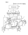
- the measuring devices 1 consists of a centrally arranged measuring table 2, which in the example shown houses an integrated rotary table 3, and the measuring devices 4 arranged around the central measuring table 2 from five sides.
- the measuring devices can be components in any selection from coordinate measuring technology as well as elements of multi-point measuring technology and shape testing technology.
- the measuring devices 4, which operate independently of one another, are arranged both laterally and above the centrally arranged workpiece 5 and have simple measuring probes 6 directed towards the workpiece 5.
- the combination with the integrated rotary table 3 allows the present measuring tasks to be divided into different measuring devices 4, which are specialized in certain measuring tasks and are arranged on the side of the workpiece.
- These measuring devices can consist of the device for determining the workpiece position, the device for checking the position, the device for checking the shape and the device for measuring the roughness.
- the measuring devices 4 are equipped with changing devices 7 for the probe 6 and the measuring heads for all measuring axes. Magazines 8 for the provision of the measuring probes and measuring heads are connected to these changing devices 7.
- This multi-point measuring device 1 is assigned a device control computer 9, which is formed from a control unit 10, an evaluation unit 11 and a memory 12.
- the measuring devices are electrically connected to the device control computer 9 via corresponding lines 13.
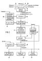
- the device control computer 9 is connected to the integrated control unit 10 and evaluation unit 11 and the mass storage device 12 to a network 14 for CAD / CAM coupling via a corresponding computer coupling interface 15.
- the device control computer 9 is also still connected via bus lines 13 to both the measuring device interface 16 and the peripheral interface 17.
- the measuring device bus line 18 connects to the measuring device interface 16, the control panel 19, the control for drives 20 with the drives 21, the adaptation 22 for the measuring systems 23, the adaptation 24 for the limit switch 25 and the control for additional devices 26 with the additional devices 27 .
- a peripheral bus line 28 can connect a terminal 29, a printer 30, a plotter 31 and a graphics tablet 32 to the peripheral interface 17.
- the mass storage interface 12 establishes the connection to the actual mass storage 33 for the control and evaluation software, for the CNC control program and for the target data.
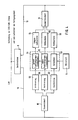
- FIG. 3 shows the flowchart for evaluating measuring points with the evaluation software, which is essentially known from coordinate measuring technology.
- the measuring axes 34, the touch probe and the transducers 36 and the rotary table axis 36 are combined, adapted and superimposed in block 37.
- the determined point coordinates X, Y and Z as well as the corresponding probing directions for X, Y and Z are forwarded and corrected on the basis of temperature correction data 38 in block 39.
- the coordinate and probing directions corrected in this way are transformed into the tool position system 14.
- the point coordinates, measurement results and trend data are stored in a parallel memory 42, while the transformed point coordinates and probing directions are also fed into the system 43 in parallel with the calculation of compensation form elements and the measurement uncertainty.
- the link is then made with the output of the measurement result, which is stored in the memory 42.
- the target / actual comparison 46 takes place, the test result of which is passed on to the output module 47 of the protocol, to the NC machine and CAD / CAM level 48 and to the statistics module 49.
- the trend data from the memory 42 are also introduced into the statistics module.
- the block diagram according to FIG. 4 shows the cantilever and bridge assembly in connection to the device control computer 9.
- the control unit 10 uses blocks 50 to actuate the major axes 51, the touch probes 52 and the transducers 53 once.
- the sensors 53 are functionally connected to the workpiece 5.
- the values determined from the major axes are fed to the evaluation unit 11 via a length measuring system 54, while corresponding measuring systems 55 also feed the determined values from the touch probes and from the sensor to the evaluation unit 11.
- the evaluation results are made available by the evaluation unit 11 via the line 13 to the device control computer 9 and processed there.
- Laser interferometers or optical length measuring systems can be used as length measuring systems.
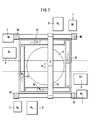
- the structure of the measuring device of the multi-point measuring device 1 can be made in a simple construction in such a way that four columns 56 are arranged at a uniform distance from one another in a square.
- the measuring table 57 with the measuring surface 58 and the measuring area 59 is located centrally between the four columns 56.
- the base frame is designated by 60.
- an installation space 61 is provided for horizontal brackets 62, while a further free space 63 is provided between the pillars 56 in order to be able to load the multi-point measuring device with workpieces, for example, and to achieve improved accessibility.
- the free space 63 is also necessary so that the cantilever arms of the measuring device can be moved without problems.
- the installation space 64 for the bridge 65 is located above the pillars 56.
- the measuring table 2 is designed as a rotary table 3 with an angle measuring device.
- FIG. 8 shows a kinematic model of the multi-point measuring device 1 which is shown in FIG. 9 as a device unit.
- the multi-point measuring device consists of a total of eleven horizontal travel axes 66, to which the bridge 65 also belongs.
- the eleven horizontal traversing axes 66 and 65 allow the probe 6 to be moved in both the X and Y directions.
- the vertical traversing axes 67 offer the possibility that the probe 6 can be moved in the Z direction. The same direction of movement in the Z coordinate takes place through the vertical sleeve 68.
- the four horizontal arms 62 in turn provide movements of the probe 6 in the two coordinate directions X and Y.
- each probe 6 can be moved in the three coordinate directions X, Y and Z independently of the other probes 67.
- the respective travel axes 66 and 67 are designed in the form of rails which are connected to the corner columns 56.
- a vertical travel axis 67 forms a vertical connection between two end-side travel rails 66.
- the measuring device 4 can be moved vertically on this vertical connection rail 67 and each has a horizontal arm 62 in the form of a quill which receives the measuring buttons 6.
- the measuring buttons can be designed as single or as multiple buttons.
- the bridge 65 is guided on the upper traversing axes in rails 66 which rest on the columns 56.
- the measuring device 4 can be moved in the Y direction on the bridge 65 and also has the vertical sleeve 68 with the measuring probe 6.
- the measuring table 2 has the integrated turntable 3 with an angle measuring device and is also movable in the coordinate directions X and Y.
Landscapes
- Physics & Mathematics (AREA)
- General Physics & Mathematics (AREA)
- Length Measuring Devices With Unspecified Measuring Means (AREA)
- A Measuring Device Byusing Mechanical Method (AREA)
- Length Measuring Devices By Optical Means (AREA)
Abstract
Die Erfindung betrifft eine flexible CNC-Vielstellenmeßeinrichtung (1), welche aus einer Kombination von Komponenten aus der Koordinatenmeßtechnik mit Elementen der Vielstellenmeßtechnik und der Formprüftechnik besteht, die in einer einzigen Meßeinrichtung miteinander verknüpft sind.
Ein aus der Koordinatenmeßtechnik im wesentlichen bekannter Grundrahmen mit Säulen (56) ist mit selbständigen und unabhängig voneinander arbeitenden Meßeinrichtungen (4) versehen. Die Meßwerterfassung und Meßwertauswertung werden durch die Meßsoftware aus der Koordinatenmeßtechnik und durch den direkten Soll-Ist-Vergleich bestimmter Meßtasterstellungen der Vielstellenmeßtechnik vorgenommen. Es ist mindestens eine als Koordinatenmeßgerät ausgerichtete Baugruppe als flexibler Einstellmeister ausgelegt. 
A base frame with columns (56), which is essentially known from coordinate measuring technology, is provided with independent and independently operating measuring devices (4). The measurement value acquisition and measurement value evaluation are carried out by the measurement software from the coordinate measurement technology and by the direct target-actual comparison of certain measurement probe positions of the multi-position measurement technology. At least one assembly designed as a coordinate measuring machine is designed as a flexible setting master.
Description
Die Erfindung betrifft eine flexible CNC-Vielstellenmeßeinrichtung, welche eine Kombination von Komponenten aus der Koordinatenmeßtechnik mit Elementen der Vielstellenmeßtechnik und der Formprüftechnik darstellt, die in einer gemeinsamen Meßeinrichtung miteinander verknüpfbar sind. Solche CNC-Vielstellenmeßeinrichtungen eignen sich insbesondere für die Integration in einen Fertigungsprozeß.The invention relates to a flexible CNC multi-point measuring device, which represents a combination of components from coordinate measuring technology with elements of multi-point measuring technology and form testing technology, which can be linked together in a common measuring device. Such CNC multi-point measuring devices are particularly suitable for integration into a manufacturing process.
An die Fertigungsmeßtechnik werden ständig höhere Anforderungen gestellt, die sich aus dem Einsatz von neuen Fertigungsverfahren und flexiblen Fertigungssystemen, der veränderten Fertigungsstrukturen und Fertigungsabläufe und der weitgehenden Automatisierung durch den Einsatz neuer Informationstechnologien ergeben. Ferner sind auch die konstruktiven Anforderungen an die Mikro- und Makrogestalt von Werkstücken zu berücksichtigen. Zu der wichtigsten Aufgabe der Fertigungsmeßtechnik gehört das Erfassen von geometrischen Merkmalen von Werkstücken (die Werkstückgestaltprüfung). Innerhalb dieses Gebietes sind für die Einsetzbarkeit von Fertigungsmeßgeräten für bestimmte Meßaufgaben immer mehrere Kriteren entscheidend.The production measurement technology is subject to constantly higher demands, which result from the use of new manufacturing processes and flexible manufacturing systems, the changed manufacturing structures and manufacturing processes and the extensive automation through the use of new information technologies. The design requirements for the micro and macro shape of workpieces must also be taken into account. One of the most important tasks of production measurement technology is the recording of geometric features of workpieces (the workpiece shape test). Within this area, several criteria are always decisive for the applicability of production measuring devices for certain measuring tasks.
Die Einsatzorte von Fertigungsmeßgeräten innerhalb eines Fertigungsbetriebes erstrecken sich auf den Wareneingang, auf Fertigungsinseln für das Bereitstellen von Korrekturwerten für Bearbeitungsmaschinen zum Zweck der Fertigungsprozeßregelung, Qualitätskontrolle, Montage und Endkontrolle des Gesamtproduktes. In all diesen Bereichen kommen heute gestaltprüfende Meßmittel zum Einsatz. Der Schwerpunkt der Fertigungsmeßtechnik im Produktionsprozeß, der bislang in der absolut genauen und extrem universellen geometrischen Gesamtprüfung von Werkstücken unter günstigen Bedingungen im Meßraum lag, wird künftig direkt in den Fertigungsbereich verschoben.The locations of manufacturing measuring devices within a manufacturing company extend to the goods receipt, on manufacturing islands for the provision of correction values for machine tools for the purpose of manufacturing process control, quality control, assembly and final inspection of the overall product. In all of these areas, design-checking measuring devices are used today. The focus of production measurement technology in the production process, which previously was the absolutely precise and extremely universal geometric overall inspection of workpieces under favorable conditions in the measuring room, will in future be shifted directly to the production area.
Dort müssen dann unter Fertigungsbedingungen in Bezug auf die Meßzeit die Anzahl und Vorbildung des Meßpersonals und die Umgebungsbedingungen vergleichbare Genauigkeiten wie im Meßraum ermöglicht werden, wobei durchaus eine Einschränkung der Flexibilität in Kauf genommen werden kann.There, under manufacturing conditions with regard to the measuring time, the number and training of the measuring personnel and the environmental conditions comparable accuracies to those in the measuring room must be made possible, whereby a restriction of flexibility can be accepted.
Zur Realisierung dieser Anforderungen besteht die Möglichkeit, einerseits die Weiterentwicklung herkömmlicher Fertigungsmeßgeräte unter weitgehender Beibehaltung grundlegender meßtechnischer Eigenschaften dieser Geräte zu betreiben oder andererseits die Entwicklung eines neuartigen Fertigungsmeßgerätes durchzuführen, welches die vorteilbringenden Komponenten herkömmlicher Fertigungsmeßgeräte in sich vereinigt.To meet these requirements, there is the possibility, on the one hand, of operating the further development of conventional manufacturing measuring devices while largely maintaining the basic metrological properties of these devices, or, on the other hand, of carrying out the development of a novel manufacturing measuring device which combines the advantageous components of conventional manufacturing measuring devices.
Ausgehend von dem bekannten Stand der Technik und den Anforderungen an die zukünftige Fertigungsmeßtechnik ist es Aufgabe der Erfindung, eine flexible CNC-Vielstellenmeßeinrichtung zu schaffen, die es erlaubt, für die immer größer werdenden Produktvarianten bei kleineren Stückzahlen mit steigenden Qualitätsanforderungen die fortlaufende Produktion zu sichern, dazu ein schnelles Messen mit geringer Meßunsicherheit zu ermöglichen und vielfältige Meßaufgabenlösungen, wie z.B. die Längenmessung, die Oberflächenmessung und die Formprüfung, anzubieten.Based on the known state of the art and the requirements for future production measurement technology, it is the object of the invention to create a flexible CNC multi-position measuring device which allows continuous production to be ensured for the ever increasing product variants in smaller quantities with increasing quality requirements, to enable fast measurement with low measurement uncertainty and a variety of measurement task solutions, such as to offer length measurement, surface measurement and shape testing.
Diese Aufgabe wird erfindungsgemäß durch den Kennzeichenteil des Patentanspruches 1 gelöst. Ausgestaltungen und Weiterbildungen des Lösungsgedankens nach Patentanspruch 1 sind den weiteren Patentansprüchen 2 bis 17 zu entnehmen.This object is achieved by the characterizing part of claim 1. Refinements and developments of the solution concept according to claim 1 can be found in the
Die erfinderischen Merkmale bieten die Vorteile, daß durch Kombination von Komponenten aus der Koordinatenmeßtechnik mit Elementen der Vielstellenmeßtechnik und der Formprüftechnik eine Verknüpfung dieser konträr erscheinenden Meßphilosophien in einem Gerät durchgeführt und damit die vorhandene meßtechnische Lücke zwischen der Koordinatenmeßtechnik als flexible Methode zur universellen Gesamtprüfung aller an beliebigen Werkstücken vorgegebenen Meßaufgaben und der Vielstellenmeßtechnik als zuverlässige Methode zur schnellen Rückführung ausgewählter und fertigungsrelevanter Werkstückmerkmale geschlossen werden kann.
Diese Synthese sichert sowohl eine hohe Meßgenauigkeit bei Absolutmessungen als auch Schnelligkeit und Reproduzierbarkeit bei der Prüfung bestimmter Gestaltmerkmale. Der Ausgangspunkt für die Konzeption dieses Fertigungsmeßsystems kann gebildet werden einerseits von dem Grundprinzip der Koordinatenmeßtechnik und andererseits von dem Grundprinzip der bekannten Vielstellenmeßtechnik. In einem von der Koordinatenmeßtechnik her bekannten stabilen Gerätegrundaufbau mit mehreren selbständigen Meßeinrichtungen oder auch Modulen werden Elemente der Vielstellenmeßtechnik, bspw. in Bezug auf Zeichnungsdaten am Meisterstück voreingestellte Mehrfachtaster und automatisierte Prüflehren, integriert. Die Meßwerterfassung und die Meßwertauswertung können durch entsprechende Erweiterung der aus der Koordinatenmeßtechnik übernommenen Meßsoftware sowohl auf dem üblichen koordinatenmeßtechnischen Weg als auch nach Art der Vielstellenmeßtechnik durch direkten Soll-Ist-Vergleich bestimmter Meßtasterstellungen erfolgen. Das bedeutet, daß die Meßtaster, ausgehend von den zeichnerisch vorgegebenen Daten, an einem ausgewählten Werkstück voreingestellt bzw. kalibriert werden. Die so fest eingestellten Meßtaster fahren nun bei allen weiteren Werkstücken mit großer Geschwindigkeit an die Meßpunkte und stellen in einem Soll-Ist-Vergleich die Meßdaten reproduzierbar fest
Die wesentlichen Eigenschaften und Vorzüge dieser neuen Vielstellenmeßeinrichtung sind die fünf voneinander unabhängigen Meßeinrichtungen, welche im wesentlichen aus einer Brücke mit senkrechter Pinole und vier Horizontalauslegern mit jeweils waagerechter Pinole bestehen. Dabei ist jede Verfahrachse mit einem eigenen Längenmeßsystem zur Erhöhung der Genauigkeit und einer Ausgleichseinrichtung für die Massenkräfte ausgerüstet, die beim Beschleunigen auftreten.The inventive features offer the advantages that, by combining components from coordinate measuring technology with elements of multi-point measuring technology and form testing technology, a link between these contradictory measuring philosophies is carried out in one device and thus the existing measuring gap between the Coordinate measuring technology as a flexible method for the universal total inspection of all measuring tasks specified on any work piece and the multi-point measuring technology as a reliable method for the quick return of selected and production-relevant workpiece characteristics can be concluded.
This synthesis ensures a high level of measurement accuracy for absolute measurements as well as speed and reproducibility when testing certain design features. The starting point for the conception of this production measuring system can be formed on the one hand by the basic principle of coordinate measuring technology and on the other hand by the basic principle of the known multi-point measuring technology. In a stable basic device structure known from coordinate measuring technology with several independent measuring devices or modules, elements of multi-point measuring technology, for example multiple probes and automated test gauges preset in relation to drawing data, are integrated. The measured value acquisition and the measured value evaluation can be carried out by appropriate expansion of the measuring software taken over from the coordinate measuring technique, both in the usual coordinate measuring technique and according to the type of multi-point measuring technique by direct target-actual comparison of certain measuring probe positions. This means that the probes are preset or calibrated on a selected workpiece based on the data specified in the drawing. The measuring probes set in this way now move to the measuring points for all other workpieces at high speed and reproducibly determine the measuring data in a target / actual comparison
The essential properties and advantages of this new multi-point measuring device are the five mutually independent measuring devices, which essentially consist of a bridge with a vertical quill and four horizontal brackets, each with a horizontal quill. Each travel axis is equipped with its own length measuring system to increase accuracy and a compensation device for the inertial forces that occur during acceleration.
Das Werkstück kann bei dieser Einrichtung von fünf verschiedenen Seiten gleichzeitig gemessen werden, ohne daß dazu komplizierte Tasterkombinationen erforderlich sind. Ferner sind kombinierte Rund- und Planlaufmessungen gleichzeitig in fünf verschiedenen Meßlinien möglich und für Formprüfungen an Wellen kann die Brückenpinole als Gegenhalter verwendet werden. Die Vielstellenmeßeinrichtung kann mit dem üblicherweise geforderten Meßbereich, bspw. 1000 mm x 1000 mm x 1200 mm hergestellt werden. Die voneinander unabhängigen Meßeinrichtungen sind Module, worunter Drei-Achs-Meßeinheiten als komplette Baueinheiten verstanden werden.With this device, the workpiece can be measured from five different sides at the same time without the need for complicated button combinations. Combined radial and axial runout measurements are also possible simultaneously in five different measuring lines and the bridge quill can be used as a counterhold for shape tests on shafts. The multi-point measuring device can be manufactured with the measuring range usually required, for example 1000 mm x 1000 mm x 1200 mm. The mutually independent measuring devices are modules, by which three-axis measuring units are understood as complete structural units.
Durch die laufende Kollisionskontrolle ist eine gegenseitige Behinderung der Pinolen ausgeschlossen. Eine als Koordinatenmeßgerät ausgelegte Baugruppe ist als flexibler Einstellmeister für die übrigen vielstellenmeßtechnisch eingesetzten Baugruppen zu verwenden, wodurch ein verkörperter Einstellmeister entfällt. Es ist eine gemeinsame Kalibrierung aller Meßeinrichtungen an einem zentral angeordneten Prüfkörper mit einer Umschlagmessung durchführbar. Ferner ist eine gemeinsame Bezugspunkbestimmung, nämlich der Nullpunkt des Bezugskoordinatensystems, durch Messung an einem zentral angebrachten versenkbaren Kugel-Normal möglich.The ongoing collision check prevents the quills from interfering with each other. A module designed as a coordinate measuring machine is to be used as a flexible setting master for the other modules used in multi-point measuring technology, as a result of which an embodied setting master is not required. A common calibration of all measuring devices can be carried out on a centrally arranged test specimen with an envelope measurement. Furthermore, a common determination of the reference point, namely the zero point of the reference coordinate system, is possible by measurement on a centrally mounted retractable sphere normal.
Durch den Einsatz mehrerer voneinander unabhängiger Meßsysteme ist eine hohe Meßpunktrate bei einer gleichzeitigen Werkstückantastung aus fünf verschiedenen Richtungen möglich. Die Meßeinrichtung kann aus standardisierten Modulen zusammengesetzt und den jeweiligen Erfordernissen mit geringem Aufwand angepaßt werden, wodurch eine Flexibilität bezüglich der Anordnung und Größe der Meßachsen erzielt wird. Durch den Modulaufbau ist eine relativ schnelle Reparaturmöglichkeit durch einfachen Modulaustausch gegeben. Durch den Einsatz mehrerer Meßeinrichtungen, z.B. zur Form-, Lage- und Rauheitsprüfung in den verschiedenen Meßarmen kann das gesamte System in Verbindung mit dem Drehtisch quasi als Rundtakt-Meßeinrichtung eingesetzt werden.The use of several independent measuring systems enables a high measuring point rate with simultaneous workpiece probing from five different directions. The measuring device can be assembled from standardized modules and adapted to the respective requirements with little effort, thereby achieving flexibility with regard to the arrangement and size of the measuring axes. The module structure allows for a relatively quick repair by simply replacing the module. By using several measuring devices, for example for shape, position and roughness testing in the different measuring arms, the entire system can be used in connection with the rotary table as a kind of rotary measuring device.
Zusammenfassend können die Hauptmerkmale der erfindungsgemäßen Vielstellenmeßeinrichtung wie folgt genannt werden:
- hohe Flexibilität bei der Konfiguration
- auf eine Werkstückteilefamilie begrenzte Flexibilität einer gewählten Konfiguration
- vielfältige Kombinationsmöglichkeiten zwischen koordinaten- und vielstellen-meßtechnischen Anwendungen
- Fortfall eines Einstellmeisters zur Kalibrierung bei vielstellen-meßtechnischen Anwendungen
- vollständige Automatisierung sämtlicher Gerätefunktionen
- modularer Aufbau durch standardisierte Baugruppen
- vollständige Integration in den Fertigungsfluß
- informationstechnische Verkettung im CAD/CAM/CAQ-Datenverbund
- hohe Zuverlässigkeit und kurze Meßzeiten sowie schnelle Rückführung von Qualitätsdaten in die Fertigung
- fertigungsorientierte Prüfaussagen für die Qualitätsregelung innerhalb der Fertigungsinsel
- gute Reproduzierbarkeit
- hohe absolute Genauigkeit der koordinaten-meßtechnischen Anwendungen
- Anwendung beliebiger Tastsysteme und
- großer Meßbereich von etwa 1000 mm x 1000 mm x 1200 mm.In summary, the main features of the multi-point measuring device according to the invention can be named as follows:
- high flexibility in configuration
- Flexibility of a selected configuration limited to a workpiece part family
- Various possible combinations between coordinate and multi-position measurement applications
- Elimination of a setting master for calibration in multi-point measurement applications
- Complete automation of all device functions
- Modular structure thanks to standardized assemblies
- full integration into the production flow
- Information technology chaining in the CAD / CAM / CAQ data network
- High reliability and short measuring times as well as quick return of quality data to the production
- Production-oriented test statements for quality control within the production island
- good reproducibility
- High absolute accuracy of the coordinate measuring technology applications
- Use of any touch probe and
- Large measuring range of approximately 1000 mm x 1000 mm x 1200 mm.
In den Zeichnungen sind Beispiele der Erfindung dargestellt, die anhand der folgenden Zeichnungsbeschreibung näher erläutert werden. In den Zeichnungen zeigen:
- Fig. 1 eine Vielstellenmeßeinrichtung in einer Blockbilddarstellung;
- Fig. 2 Hardwarekomponenten für die CNC-Vielstellenmeßeinrichtung im Blockschaltbild;
- Fig. 3 einen Ablaufplan für die Auswertung von Meßpunkten mit Auswertesoftware der Vielstellenmeßeinrichtung;
- Fig. 4 ein Blockschaltbild einer Ausleger- oder Brückenbaugruppe der Vielstellenmeßeinrichtung;
- Fig. 5 ein Grundgestell der Vielstellenmeßeinrichtung mit Einbauräumen für die Meßgeräte in schematischer Draufsicht;
- Fig. 6 das Grundgestell nach Fig. 5 in einer schematischen Vorderansicht;
- Fig. 7 den prinzipiellen Aufbau des Vielstellenmeßsystems mit den Systemkomponenten in schematischer Darstellung;
- Fig. 8 ein kinematisches Modell der Vielstellenmeßeinrichtung in perspektivischer Ansicht;
- Fig. 9 die Vielstellenmeßeinrichtung nach Fig. 8 in perspektivischer Ansicht mit dem Grundrahmen und entsprechenden Meßeinrichtungen.
- 1 shows a multi-point measuring device in a block diagram representation;
- 2 hardware components for the CNC multi-position measuring device in the block diagram;
- 3 shows a flow chart for the evaluation of measuring points with evaluation software of the multi-point measuring device;
- 4 shows a block diagram of a cantilever or bridge assembly of the multi-point measuring device;
- 5 shows a basic frame of the multi-point measuring device with installation spaces for the measuring devices in a schematic plan view;
- FIG. 6 shows the base frame according to FIG. 5 in a schematic front view;
- 7 shows the basic structure of the multi-point measuring system with the system components in a schematic representation;
- 8 shows a kinematic model of the multi-point measuring device in a perspective view;
- Fig. 9, the multi-point measuring device according to Fig. 8 in a perspective view with the base frame and corresponding measuring devices.
Die Vielstellenmeßeinrichtung 1 besteht gemäß dem Prinzipaufbau in Fig. 1 aus einem zentral angeordneten Meßtisch 2, welcher im dargestellten Beispiel einen integrierten Drehtisch 3 aufnimmt, und den von fünf Seiten um den zentralen Meßtisch 2 angeordneten Meßeinrichtungen 4. Die Meßeinrichtungen können in beliebiger Auswahl sowohl Komponenten aus der Koordinatenmeßtechnik als auch Elemente der Vielstellemeßtechnik und der Formprüftechnik darstellen. Die voneinander unabhängig arbeitenden Meßeinrichtungen 4 sind sowohl seitlich als auch oberhalb des zentral angeordneten Werkstücks 5 angeordnet und weisen auf das Werkstück 5 gerichtete einfache Meßtaster 6 auf.1 consists of a centrally arranged measuring table 2, which in the example shown houses an integrated rotary table 3, and the measuring devices 4 arranged around the central measuring table 2 from five sides. The measuring devices can be components in any selection from coordinate measuring technology as well as elements of multi-point measuring technology and shape testing technology. The measuring devices 4, which operate independently of one another, are arranged both laterally and above the centrally arranged
Durch die Kombination mit dem integrierten Drehtisch 3 kann eine Aufteilung der vorliegenden Meßaufgaben auf verschiedene, auf bestimmte Meßaufgaben spezialisierte und seitlich des Werkstückes angeordnete Meßeinrichtungen 4 erfolgen. Diese Meßeinrichtungen können in der Einrichtung zum Ermitteln der Werkstücklage, der Einrichtung zur Lageprüfung, der Einrichtung zur Formprüfung und der Einrichtung zur Rauheitmessung bestehen. Die Meßeinrichtungen 4 sind mit Wechseleinrichtungen 7 für die Meßtaster 6 und die Meßköpfe für alle Meßachsen ausgerüstet. An diese Wechseleinrichtungen 7 sind Magazine 8 für die Bereitstellung der Meßtaster und Meßköpfe angeschlossen. Dieser Vielstellenmeßeinrichtung 1 ist ein Geräteleitrechner 9 zugeordnet, welcher aus einer Steuereinheit 10, einer Auswerteeinheit 11 und einem Speicher 12 gebildet ist. Die Meßeinrichtungen sind über entsprechende Leitungen 13 mit dem Geräteleitrechner 9 elektrisch verbunden.The combination with the integrated rotary table 3 allows the present measuring tasks to be divided into different measuring devices 4, which are specialized in certain measuring tasks and are arranged on the side of the workpiece. These measuring devices can consist of the device for determining the workpiece position, the device for checking the position, the device for checking the shape and the device for measuring the roughness. The measuring devices 4 are equipped with changing
Wie insbesondere Fig. 2 zeigt, ist der Geräteleitrechner 9 mit der integrierten Steuereinheit 10 und Auswerteeinheit 11 sowie dem Massespeicher 12 an ein Netzwerk 14 zur CAD/CAM-Ankopplung über ein entsprechendes Rechnerkopplungs-Interface 15 verbunden. Der Geräteleitrechner 9 ist außerdem noch über Busleitungen 13 sowohl mit dem Meßgeräte-Interface 16 und dem Peripherie-Interface 17 verbunden. Die Meßgerätebusleitung 18 schließt an das Meßgeräte-Interface 16 das Bedienpult 19, die Steuerung für Antriebe 20 mit den Antrieben 21, die Anpassung 22 für die Meßsysteme 23, die Anpassung 24 für den Grenzschalter 25 sowie die Steuerung für Zusatzeinrichtungen 26 mit den Zusatzeinrichtungen 27 an. Eine Peripherie-Busleitung 28 kann ein Terminal 29, einen Drucker 30, einen Plotter 31 und ein Graphiktablett 32 mit dem Peripherie-Interface 17 verbinden. Das Massespeicher-Interface 12 stellt die Verbindung zu dem eigentlichen Massespeicher 33 für die Steuer- und Auswertesoftware, für das CNC-Steuerprogramm und für die Soll-Daten her.As shown in FIG. 2 in particular, the
Aus Fig. 3 geht der im wesentlichen aus der Koordinatenmeßtechnik bekannte Ablaufplan für die Auswertung von Meßpunkten mit der Auswertesoftware hervor. Die Meßachsen 34, das Tastsystem und die Aufnehmer 36 sowie die Drehtischachse 36 werden im Block 37 zusammengefaßt, angepaßt und überlagert. Die ermittelten Punktkoordinaten X, Y und Z sowie die entsprechenden Antastrichtungen für X, Y und Z werden weitergeleitet und anhand von Temperaturkorrekturdaten 38 im Block 39 korrigiert. Nach gleichzeitiger Ermittlung der Werkzeuglagedaten 40 werden die so korrigierten Koordinaten- und Antastrichtungen in das Werkzeuglagesystem 14 transformiert. Die Punktkoordinaten, Meßergebnisse und Trenddaten werden in einem parallelen Speicher 42 abgelegt, während die transformierten Punktkoordinaten und Antastrichtungen außerdem parallel zur Berechnung von Ausgleichsformelementen und der Meßunsicherheit in das System 43 geleitet werden. Anschließend erfolgt die Verknüpfung mit der Ausgabe des Meßergebnisses, welches im Speicher 42 abgelegt wird. Durch Hereingabe der Sollgeometrie aus dem CAD/CAM-System findet der Soll-Ist-Vergleich 46 statt, dessen Prüfergebnis an das Ausgabemodul 47 des Protokolls, an die NC-Maschine und CAD/CAM-Ebene 48 sowie an das Statistikmodul 49 weitergegeben wird. In das Statistikmodul werden zusätzlich auch die Trenddaten aus dem Speicher 42 eingeleitet.3 shows the flowchart for evaluating measuring points with the evaluation software, which is essentially known from coordinate measuring technology. The measuring axes 34, the touch probe and the
Das Blockschaltbild nach Fig. 4 zeigt die Ausleger- und Brückenbaugruppe in der Verbindung zum Geräteleitrechner 9. Von der Steuereinheit 10 wird über die Blöcke 50 die Ansteuerung einmal der Großachsen 51, der Tastsysteme 52 und der Aufnehmer 53 vorgenommen. Dabei stehen die Aufnehmer 53 in Funktionsverbindung mit dem Werkstück 5. Die ermittelten Werte von den Großachsen werden über ein Längenmeßsystem 54 der Auswerteeinheit 11 zugeleitet, während entsprechende Meßsysteme 55 die ermittelten Werte aus den Tastsystemen und aus dem Aufnehmer ebenfalls der Auswerteeinheit 11 zuleiten. Die Auswerteergebnisse werden von der Auswerteeinheit 11 über die Leitung 13 wieder dem Geräteleitrechner 9 zur Verfügung gestellt und dort verarbeitet. Als Längenmeßsysteme können Laserinterferometer oder auch optische Längenmeßsysteme eingesetzt sein.The block diagram according to FIG. 4 shows the cantilever and bridge assembly in connection to the
Der Meßgeräteaufbau der Vielstellenmeßeinrichtung 1 kann in einfacher Bauweise so vorgenommen sein, daß vier Säulen 56 in gleichmäßigem Abstand zueinander im Viereck angeordnet sind. Zentral zwischen den vier Säulen 56 befindet sich der Meßtisch 57 mit der Meßfläche 58 und dem Meßbereich 59. Mit 60 ist das Fundamentgestell bezeichnet. An den vier Seiten zum Meßtisch 57 ist jeweils ein Einbauraum 61 für Horizontalausleger 62 vorgesehen, während jeweils zwischen den Pfeilern 56 ein weiterer Freiraum 63 eingerichtet ist, um die Vielstellenmeßeinrichtung bspw. mit Werkstücken beladen zu können und um eine verbesserte Zugänglichkeit zu erzielen. Der Freiraum 63 ist außerdem notwendig, damit die Auslegerarme der Meßeinrichtung störungsfrei bewegt werden können. Über den Pfeilern 56 befindet sich schließlich noch der Einbauraum 64 für die Brücke 65.The structure of the measuring device of the multi-point measuring device 1 can be made in a simple construction in such a way that four
Wie dazu die Fig. 7 zeigt, ist der Meßtisch 2 als Drehtisch 3 mit einer Winkelmeßeinrichtung ausgeführt.As shown in FIG. 7, the measuring table 2 is designed as a rotary table 3 with an angle measuring device.
Fig. 8 zeigt ein kinematisches Modell der Vielstellenmeßeinrichtung 1 welches in Fig. 9 als Geräteeinheit dargestellt ist. Ausgehend von den im Rechteck stehenden Ecksäulen 56, die um den zental angeordneten Drehtisch 3 mit Winkelmeßeinrichtung angeordnet sind, besteht die Vielstellenmeßeinrichtung aus insgesamt elf Horizontalverfahrachsen 66 zu denen auch die Brücke 65 gehört. Ferner sind vier Vertikalverfahrachsen 67 und vier Horizontalausleger 62 und eine Vertikalpinole 68 vorhanden. Sämtliche Verfahrachsen sind mit integrierten Längenmeßsystemen und Massenkraft-Ausgleichseinrichtungen versehen. Die elf Horizontalverfahrachsen 66 bzw. 65 erlauben eine Bewegung der Meßtaster 6 sowohl in X- als auch in Y-Richtung. Die Vertikalverfahrachsen 67 bieten die Möglichkeit, daß der Meßtaster 6 in Z-Richtung bewegbar ist. Die gleiche Bewegungsrichtung in der Z-Koordinate erfolgt durch die Vertikalpinole 68. Durch die vier Horizontalausleger 62 sind wiederum Bewegungen des Meßtasters 6 in den beiden Koordinatenrichtungen X bzw. Y gegeben.FIG. 8 shows a kinematic model of the multi-point measuring device 1 which is shown in FIG. 9 as a device unit. Starting from the
Durch dieses System ist jeder Meßtaster 6 in den drei Koordinatenrichtungen X, Y, und Z unabhängig von den übrigen Meßtastern 67 verfahrbar. Die jeweiligen Verfahrachsen 66 und 67 sind in Form von Schienen ausgeführt, welche mit den Ecksäulen 56 verbunden sind. So bildet jeweils eine vertikale Verfahrachse 67 eine vertikale Verbindung zwischen zwei endseitige Verfahrschienen 66. Auf dieser vertikalen Verbindungsschiene 67 ist die Meßeinrichtung 4 senkrecht verfahrbar und besitzt jeweils einen Horizontalausleger 62 in Form einer Pinole, welche die Meßtaster 6 aufnimmt. Entsprechend dem Beispiel in Fig. 7 können die Meßtaster als Einfach- sowie auch als Mehrfachtaster ausgebildet sein. Die Brücke 65 ist auf den oberen Verfahrachsen verfahrbar in Schienen 66 geführt, die auf den Säulen 56 ruhen. Auf der Brücke 65 ist die Meßeinrichtung 4 in der Y-Richtung bewegbar und weist zudem die Vertikalpinole 68 mit dem Meßtaster 6 auf. Der Meßtisch 2 besitzt den integrierten Drehtisch 3 mit einer Winkelmeßeinrichtung und ist zudem in den Koordinatenrichtungen X und Y bewegbar.With this system, each
Claims (17)
dadurch gekennzeichnet,
daß ein aus der Koordinatenmeßtechnik an sich bekannter Grundrahmen mit selbständigen Meßeinrichtungen (Module) vorgesehen ist, in dem Einzelelemente der Vielstellenmeßtechnik integriert sind, wobei die Meßwerterfassung und die Meßwertauswertung sowohl durch die Meßsoftware aus der Koordinatenmeßtechnik als auch gemäß der Vielstellenmeßtechnik durch den Soll-Ist-Vergleich bestimmter Meßtasterstellungen erfolgt, wobei als Soll-Stellung die nach der Zeichnung am Werkstück erfaßten unterschiedlichen Meßdaten zugrundeliegen, und
daß mindestens eine als Koordinatenmeßgerät ausgelegte Baugruppe als flexibler Einstellmeister ausgelegt ist.1. Flexible CNC multi-position measuring device, which represents a combination of components from coordinate measuring technology with elements of multi-point measuring technology and form testing technology, which can be linked together in a common measuring device,
characterized,
that a base frame known per se from coordinate measuring technology with independent measuring devices (modules) is provided, in which individual elements of the multi-point measuring technology are integrated, the measured value acquisition and the measured value evaluation both by the measuring software from the coordinate measuring technology and according to the multi-point measuring technology by the target / actual Certain measuring probe positions are compared, the different measuring data recorded on the workpiece as the target position, and
that at least one module designed as a coordinate measuring machine is designed as a flexible setting master.
dadurch gekennzeichnet,
daß die einzelnen Teilsysteme aus der Koordinatenmeßtechnik und aus der Vielstellenmeßtechnik im wesentlichen unabhängig voneinander arbeiten, jedoch einer zentral gesteuerten Kollisionskontrolle zugeordnet sind.2. Multi-point measuring device according to claim 1,
characterized,
that the individual subsystems from coordinate measuring technology and from multi-point measuring technology work essentially independently of one another, but are assigned to a centrally controlled collision control.
dadurch gekennzeichnet,
daß die Systemhauptgruppen aus einem Grundgestell als Geräte- bzw. Maschinenfundament mit Tragsäulen (56), einem Meßtisch (2,3) wahlweise in der Ausführung als Drehtisch (3) oder Schaltteller oder feststehender Meßtisch (2), mindestens einer Brücke (65), zumindest einem Ausleger (62), Wechseleinrichtungen (7) für Taster und Tastsysteme, einer Gerätesteuereinheit (10), einer Auswerteeinheit (11) und einem Geräteleitrechner (9) gebildet sind.3. Multi-point measuring device according to claims 1 and 2,
characterized,
that the main system groups from a base frame as a device or machine foundation with support columns (56), a measuring table (2,3) optionally in the design as a rotary table (3) or switching table or fixed measuring table (2), at least one bridge (65), At least one arm (62), changing devices (7) for buttons and touch systems, a device control unit (10), an evaluation unit (11) and a device control computer (9) are formed.
dadurch gekennzeichnet,
daß der Geräteleitrechner (9) einen Steuerteil (10) und einen Auswerteteil (11) aufweist, die über ein Bussystem miteinander und mit einem Meßgeräte-Interface (16), einem Massenspeicher-Interface (12) und einem Peripherie-Interface (17) verbunden sind, wobei der Meßgerätebus im wesentlichen das Bedienpult (19), die Steuerung (20) für Antriebe (21), die Anpassung (22,24) an Meßsysteme (23) und Grenzschalter (25) sowie die Steuerung (26) für Zusatzeinrichtungen (22) aufweist, während der Peripheriebus ein Terminal (29), einen Drucker (30), einen Plotter (31) und ein Graphiktablett (32) besitzt und das Massenspeicher-Interface (12) einen Massenspeicher (33) und die Steuer- und Auswertesoftware, ein CNC-Steuerprogramm und die jeweiligen Soll-Daten eines Meßobjektes aufweist.4. Multi-point measuring device according to claim 3,
characterized,
that the device control computer (9) has a control part (10) and an evaluation part (11) which are connected to one another via a bus system and to a measuring device interface (16), a mass storage interface (12) and a peripheral interface (17) are, the measuring device bus essentially the control panel (19), the controller (20) for drives (21), the adaptation (22, 24) to measuring systems (23) and limit switches (25) and the controller (26) for additional devices ( 22), while the peripheral bus has a terminal (29), a printer (30), a plotter (31) and a graphics tablet (32) and the mass storage interface (12) has a mass storage device (33) and the control and evaluation software , a CNC control program and the respective target data of a measurement object.
dadurch gekennzeichnet,
daß mehrere Prozeßabläufe parallel schaltbar und zu einem einzigen Meßprotokoll zum Zweck der sofortigen Bewertung aller Meßergebnisse für ein Meßobjekt zusammenfügbar sind.5. multi-point measuring device according to claims 3 and 4,
characterized,
that several process sequences can be connected in parallel and combined into a single measurement protocol for the purpose of immediate evaluation of all measurement results for a measurement object.
dadurch gekennzeichnet,
daß insgesamt vier Säulen (56) vorgesehen sind, die sich in beliebigen, paarweisen Abständen zueinander im Rechteck um den zentralen Meßtisch (2) gruppieren, daß an die vier Seiten des Meßtisches (2) jeweils ein Einbauraum (61) für Horizontal-Ausleger (62) und zwischen den Säulen (56) jeweils weitere Freiräume (63) vorgesehen sind, während sich über den Säulen (56) der Einbauraum (64) für eine Brücke (65) befindet, und daß in dem Rahmenaufbau mehrere voneinander unabhängig arbeitende Meßeinrichtungen (4) mit Meßtastern (6) seitlich und oberhalb des zentral eingerichteten Werkstückes (5) angeordnet sind, wobei das Werkstück (5) wahlweise auf einem Drehtisch (3,2) aufgelegt ist und Meßeinrichtungen (4) für die Ermittlung der Werkstücklage, der Lageprüfung, der Formprüfung und der Rauhheitsmessung vorgesehen sind.6. multi-point measuring device according to claims 1 to 3,
characterized,
that a total of four columns (56) are provided, which are grouped at random, pair-wise distances from each other in a rectangle around the central measuring table (2), that on each of the four sides of the measuring table (2) there is an installation space (61) for horizontal arms ( 62) and between the columns (56) further free spaces (63) are provided, while above the columns (56) there is the installation space (64) for a bridge (65), and that in the frame structure several mutually independent measuring devices ( 4) with measuring buttons (6) are arranged laterally and above the centrally arranged workpiece (5), the workpiece (5) optionally being placed on a turntable (3,2) and measuring devices (4) for determining the workpiece position and the position check , the shape test and the roughness measurement are provided.
dadurch gekennzeichnet,
daß fünf voneinander unabhängige Meßeinrichtungen (4) mit vier im Rechteck angeordneten Säulen (56) mit Befestigungseinrichtungen für Horizontalverfahrachsen (66) vorgesehen sind, die um einen zentralen, wahlweise als Drehtisch (3) mit Winkelmeßeinrichtung ausgebildeten Meßtisch (2) gruppiert sind, wobei insgesamt elf Horizontalverfahrachsen (66), vier Vertikalverfahrachsen (67) und vier Horizontalausleger (62) sowie eine Vertikalpinole (68) eingerichtet sind, die alle mit einem integrierten Längenmeßsystem und Massenausgleichseinrichtungen ausgerüstet sind.7. multi-point measuring device according to claims 1 to 6,
characterized,
that five mutually independent measuring devices (4) are provided with four columns (56) arranged in a rectangle with fastening devices for horizontal traversing axes (66), which are grouped around a central measuring table (2) optionally designed as a rotary table (3) with an angle measuring device, with a total of eleven horizontal traversing axes (66), four vertical traversing axes (67) and four horizontal brackets (62) and a vertical quill (68) are set up, all of which are equipped with an integrated length measuring system and mass balancing devices.
dadurch gekennzeichnet,
daß jeweils zwischen zwei benachbarten Säulen (56) eine Meßeinrichtung (4) auf zwei parallelen Horizontalverfahrachsen (66) bewegbar ist, welche über einen vertikalen Verbindungsträger eine Vertikalverfahrachse (67) und zusätzlich einen rechtwinklig zur Horizontal- und Vertikalverfahrachse bewegbaren Horizontalausleger (62) besitzt, welcher die Meßtaster (6) zur Antastung des Meßobjektes (5) aufnimmt.8. multi-point measuring device according to claim 7,
characterized,
that in each case between two adjacent columns (56) a measuring device (4) can be moved on two parallel horizontal travel axes (66), which has a vertical travel axis (67) via a vertical connecting support and additionally a horizontal arm (62) movable at right angles to the horizontal and vertical travel axis, which receives the probe (6) for probing the test object (5).
dadurch gekennzeichnet,
daß die Brücke (65) über den Säulen (56) eine Meßeinrichtung (4) aufweist, die eine Vertikalpinole (8) besitzt und zusammen mit der Brücke (65) in jeweils rechtwinklig zueinander angeordneten Horizontalverfahrachsen (66) bewegbar ist und Meßtaster (6) für die Antastung an ein Meßobjekt (5) aufnimmt.9. multi-point measuring device according to claim 7,
characterized,
that the bridge (65) above the columns (56) has a measuring device (4) which has a vertical quill (8) and can be moved together with the bridge (65) in horizontal travel axes (66) arranged at right angles to each other and measuring sensors (6) for probing a test object (5).
dadurch gekennzeichnet,
daß alle Koordinatenverfahrachsen CNC-gesteuert sind.10. Multi-point measuring device according to the preceding claims,
characterized,
that all coordinate traversing axes are CNC-controlled.
dadurch gekennzeichnet,
daß jede Meßeinrichtung (4) ein eigenes Wechselmagazin (8) und eine Wechseleinrichtung (7) für Tastelemente (6) und Meßköpfe aufweist.11. Multi-point measuring device according to the preceding claims,
characterized,
that each measuring device (4) has its own changing magazine (8) and a changing device (7) for probe elements (6) and measuring heads.
dadurch gekennzeichnet,
daß Dreh-Schwenk-Taster eingesetzt sind.12. Multi-point measuring device according to the preceding claims,
characterized,
that rotary swivel buttons are used.
dadurch gekennzeichnet,
daß die Auskragung der seitlichen Ausleger (62) kleiner ist als der Meßbereich in Richtung der Auslegerbewegung, mindestens jedoch dem halben Meßbereich entspricht.13. Multi-point measuring device according to the preceding claims,
characterized,
that the cantilever of the lateral arms (62) is smaller than the measuring range in the direction of the boom movement, but at least corresponds to half the measuring range.
dadurch gekennzeichnet,
daß der Drehtisch (3) als Meßtisch (2) um die Horizontalachsen kippbar ist.14. Multi-point measuring device according to the preceding claims,
characterized,
that the turntable (3) can be tilted around the horizontal axes as a measuring table (2).
dadurch gekennzeichnet,
daß als Längenmeßeinrichtungen Laserinterferometer eingesetzt sind.15. Multi-point measuring device according to the preceding claims,
characterized,
that laser interferometers are used as length measuring devices.
dadurch gekennzeichnet,
daß als Längenmeßeinrichtungen inkrementale Meßsysteme und wahlweise kapazitive Meßstäbe eingesetzt sind.16. Multi-point measuring device according to the preceding claims,
characterized,
that incremental measuring systems and optionally capacitive measuring rods are used as length measuring devices.
dadurch gekennzeichnet,
daß in einem großen Drehtisch (3) oder Meßtisch (2) mehrere kleine Drehtische integriert sind.17. Multi-point measuring device according to the preceding claims,
characterized,
that several small rotary tables are integrated in a large rotary table (3) or measuring table (2).
Applications Claiming Priority (2)
| Application Number | Priority Date | Filing Date | Title |
|---|---|---|---|
| DE19873714862 DE3714862A1 (en) | 1987-05-05 | 1987-05-05 | FLEXIBLE CNC MULTIPLE-POINT MEASURING DEVICE |
| DE3714862 | 1987-05-05 |
Publications (3)
| Publication Number | Publication Date |
|---|---|
| EP0289983A2 true EP0289983A2 (en) | 1988-11-09 |
| EP0289983A3 EP0289983A3 (en) | 1990-06-20 |
| EP0289983B1 EP0289983B1 (en) | 1992-11-11 |
Family
ID=6326838
Family Applications (1)
| Application Number | Title | Priority Date | Filing Date |
|---|---|---|---|
| EP88107045A Expired - Lifetime EP0289983B1 (en) | 1987-05-05 | 1988-05-03 | Flexible cnc-multipoint measuring device |
Country Status (4)
| Country | Link |
|---|---|
| US (1) | US4953306A (en) |
| EP (1) | EP0289983B1 (en) |
| JP (1) | JPS63285407A (en) |
| DE (2) | DE3714862A1 (en) |
Cited By (5)
| Publication number | Priority date | Publication date | Assignee | Title |
|---|---|---|---|---|
| DE3836540A1 (en) * | 1988-10-27 | 1990-05-03 | Lemmerz Werke Kgaa | Multiposition measuring device for measuring motor vehicle wheels, their rims and/or wheel discs (naves) |
| EP0417677A1 (en) * | 1989-09-11 | 1991-03-20 | Industrie-Handels-Aktiengesellschaft | Device for measuring distances on a workpiece with a slide gauge provided with a digital indication of these distances |
| CH678890A5 (en) * | 1989-09-11 | 1991-11-15 | Inhag Ind Handels Ag | Measuring arrangement for distances on workpiece |
| WO1993014367A3 (en) * | 1992-01-08 | 1993-09-30 | Rank Taylor Hobson Ltd | Metrological apparatus |
| EP0802393A3 (en) * | 1996-04-15 | 1998-04-15 | Carl Zeiss | Measuring device for measuring the dimension of workpieces |
Families Citing this family (29)
| Publication number | Priority date | Publication date | Assignee | Title |
|---|---|---|---|---|
| GB2202659B (en) * | 1987-02-23 | 1991-07-17 | Mitutoyo Corp | Coordinate measuring instrument and method of generating pattern data concerning shape of work to be measured |
| DE3941144C2 (en) * | 1989-12-13 | 1994-01-13 | Zeiss Carl Fa | Coordinate measuring device for the contactless measurement of an object |
| US5165296A (en) * | 1990-01-12 | 1992-11-24 | Ken Yanagisawa | Drive system |
| DE4022672A1 (en) * | 1990-07-17 | 1992-01-23 | Inst Produktionstechnik Karlsr | Multiple position measurement appts. e.g. for automatic lathe - has transducers for different workpiece dimension independently positioned on parallel guide by NC drive |
| US5251156A (en) * | 1990-08-25 | 1993-10-05 | Carl-Zeiss-Stiftung, Heidenheim/Brenz | Method and apparatus for non-contact measurement of object surfaces |
| SE468727B (en) * | 1991-07-09 | 1993-03-08 | Johansson Ab C E | MACHINE STAND, SPECIFICALLY BEFORE THE COORDINATE MEASURING MACHINERY, WANTED TO EXECUTE THE MACHINE STAND |
| GB9120029D0 (en) * | 1991-09-19 | 1991-11-06 | System E Controls Ltd | Measuring apparatus and method |
| US5314397A (en) * | 1992-07-31 | 1994-05-24 | Ford Motor Company | Positioning apparatus for multiple-spindle machining |
| US5477618A (en) * | 1994-05-03 | 1995-12-26 | Gibson; Stephen P. | Sand core dimension checking apparatus |
| KR0141161B1 (en) * | 1995-03-20 | 1998-07-01 | 이대원 | Stage device with rotary table and driving method of stage device |
| IT1280989B1 (en) * | 1995-10-20 | 1998-02-11 | Dea Spa | CALIBER FOR DIMENSIONAL TESTING OF PIECES. |
| US5881470A (en) * | 1996-08-21 | 1999-03-16 | Nearfield Systems Incorporated | Vertical tower for a two-axis measurement system |
| US5806199A (en) * | 1996-11-26 | 1998-09-15 | Everett Pattern & Manufacturing Inc. | Three-dimensional part measurement system |
| CA2254851A1 (en) * | 1997-03-11 | 1998-09-17 | Werner Haug | Device for measuring volume |
| KR100355558B1 (en) * | 1997-06-16 | 2002-12-26 | 한국전기초자 주식회사 | Inspection device and inspection method of funnel assembly for cathode ray tube |
| US6115925A (en) * | 1998-05-01 | 2000-09-12 | Powerchip Semiconductor Corp. | Probepin-adjusting jig |
| FI108337B (en) * | 1998-05-20 | 2002-01-15 | Autorobot Finland | Installation and procedure for the direction of a car body when meeting the car body |
| US6470587B1 (en) | 1999-07-09 | 2002-10-29 | Vought Aircraft Industries, Inc. | Method and system for part measurement and verification |
| US6473987B1 (en) * | 1999-12-28 | 2002-11-05 | Accretech Usa, Inc. | Method for measuring wafer thickness |
| DE10136388A1 (en) * | 2001-07-26 | 2003-02-13 | Zeiss Carl | Measurement system for the correct assembly of an objective lens system, for use in semiconductor lithography, has a tactile position measurement element and an angular measurement element with a common reference plane |
| US6742273B2 (en) * | 2002-08-30 | 2004-06-01 | Tokyo Seimitsu Co., Ltd. | Workpiece measuring apparatus |
| WO2006077629A1 (en) * | 2005-01-19 | 2006-07-27 | Mitsubishi Denki Kabushiki Kaisha | Positioning device and positioning method |
| CN1924519B (en) * | 2005-09-02 | 2011-11-30 | 鸿富锦精密工业(深圳)有限公司 | Multiple point measuring system and method |
| JP6113998B2 (en) * | 2012-10-18 | 2017-04-12 | 株式会社ミツトヨ | Shape measuring machine, method for adjusting shape measuring machine, and shape measuring method |
| CN103344161A (en) * | 2013-07-02 | 2013-10-09 | 景鑫精密组件(昆山)有限公司 | Quick measuring fixture |
| WO2015147910A1 (en) * | 2014-03-24 | 2015-10-01 | Marposs Corporation | Apparatus for inspecting machined bores |
| US9581424B2 (en) * | 2014-12-09 | 2017-02-28 | Tokyo Seimitsu Co., Ltd. | Roundness measuring apparatus |
| JP6530974B2 (en) * | 2015-06-10 | 2019-06-12 | 株式会社ミツトヨ | Collision prevention device of measuring machine |
| DE102017207841A1 (en) * | 2017-05-10 | 2018-11-15 | Robert Bosch Gmbh | Device for detecting a layer thickness of a coated component, method |
Family Cites Families (9)
| Publication number | Priority date | Publication date | Assignee | Title |
|---|---|---|---|---|
| CH447626A (en) * | 1966-08-10 | 1967-11-30 | Vitale Pasquale | Apparatus for performing central perspective of a distant object, and method of operating the apparatus |
| US3499227A (en) * | 1968-05-06 | 1970-03-10 | Caterpillar Tractor Co | Contour recorder |
| US3594909A (en) * | 1969-02-26 | 1971-07-27 | United States Steel Corp | Apparatus for measuring a dimension of a member |
| US3750295A (en) * | 1971-07-22 | 1973-08-07 | Werkzeugmasch Veb | Measuring machine |
| IT1144709B (en) * | 1981-05-15 | 1986-10-29 | Dea Spa | DIMENSIONAL MEASUREMENT SYSTEM SERVED BY A MULTIPLE OF OPERATING ARMS AND CONTROLLED BY A CALCULATOR SYSTEM |
| GB2112140B (en) * | 1981-12-16 | 1985-08-07 | Mauser Werke Oberndorf | Coordinate measuring machine |
| US4631834A (en) * | 1984-04-20 | 1986-12-30 | Mitutuoyo Mfg. Co., Ltd. | Coordinate measuring instrument |
| GB8605325D0 (en) * | 1986-03-04 | 1986-04-09 | Rank Taylor Hobson Ltd | Workpiece position control |
| JPH0647A (en) * | 1992-04-14 | 1994-01-11 | Ee P S:Kk | Extermination of small insect in indoor air |
-
1987
- 1987-05-05 DE DE19873714862 patent/DE3714862A1/en active Granted
-
1988
- 1988-04-20 US US07/183,828 patent/US4953306A/en not_active Expired - Fee Related
- 1988-04-21 JP JP63099282A patent/JPS63285407A/en active Pending
- 1988-05-03 DE DE8888107045T patent/DE3875790D1/en not_active Expired - Fee Related
- 1988-05-03 EP EP88107045A patent/EP0289983B1/en not_active Expired - Lifetime
Cited By (7)
| Publication number | Priority date | Publication date | Assignee | Title |
|---|---|---|---|---|
| DE3836540A1 (en) * | 1988-10-27 | 1990-05-03 | Lemmerz Werke Kgaa | Multiposition measuring device for measuring motor vehicle wheels, their rims and/or wheel discs (naves) |
| EP0417677A1 (en) * | 1989-09-11 | 1991-03-20 | Industrie-Handels-Aktiengesellschaft | Device for measuring distances on a workpiece with a slide gauge provided with a digital indication of these distances |
| CH678890A5 (en) * | 1989-09-11 | 1991-11-15 | Inhag Ind Handels Ag | Measuring arrangement for distances on workpiece |
| WO1993014367A3 (en) * | 1992-01-08 | 1993-09-30 | Rank Taylor Hobson Ltd | Metrological apparatus |
| EP0802393A3 (en) * | 1996-04-15 | 1998-04-15 | Carl Zeiss | Measuring device for measuring the dimension of workpieces |
| US5901455A (en) * | 1996-04-15 | 1999-05-11 | Carl-Zeiss-Stiftung Trading As Carl Zeiss | Measuring device for measuring workpieces |
| USRE37695E1 (en) * | 1996-04-15 | 2002-05-14 | Carl-Zeiss-Stiftung | Measuring device for measuring workpieces |
Also Published As
| Publication number | Publication date |
|---|---|
| US4953306A (en) | 1990-09-04 |
| EP0289983A3 (en) | 1990-06-20 |
| EP0289983B1 (en) | 1992-11-11 |
| JPS63285407A (en) | 1988-11-22 |
| DE3714862A1 (en) | 1988-11-17 |
| DE3875790D1 (en) | 1992-12-17 |
| DE3714862C2 (en) | 1992-04-02 |
Similar Documents
| Publication | Publication Date | Title |
|---|---|---|
| EP0289983B1 (en) | Flexible cnc-multipoint measuring device | |
| DE3784047T2 (en) | Calibration procedure for a coordinate measuring machine and similar devices. | |
| DE69106222T2 (en) | Device for continuous error measurement of workpiece shapes and measuring methods for using the device. | |
| EP1393012B1 (en) | Method for determining the properties of a co-ordinate measuring device and test object associated therewith | |
| EP0638781B1 (en) | Calibration-procedure to determine and to compensate for the different measuring-forces in coordinate measuring machines | |
| DE69225680T2 (en) | Automated maintenance procedure for digital numerically controlled machines | |
| EP2972078B1 (en) | Method for correcting an angular deviation when operating a coordinate measuring machine | |
| WO2008141608A2 (en) | Device and method for calibrating swivel assemblies, particularly on cutting machines | |
| DE102020206719A1 (en) | Position measuring method and position measuring system for an object in a machine tool | |
| DE10339194B4 (en) | Method for determining systematic geometric deviations in technical multi-body systems | |
| DE3785645T2 (en) | TOOL SETTING CHECK. | |
| DE102020213847A1 (en) | Correction value measuring method and correction value measuring system of a position measuring sensor in a machine tool | |
| DE602005005839T2 (en) | USE OF SURFACE TESTS | |
| EP1019669B1 (en) | Device for detecting the position of two bodies | |
| DE102017126198B4 (en) | Method and system for gaugeless measurement of a thread | |
| DE3781674T2 (en) | POSITION DETERMINATION METHOD WITHIN THE MEASURING SPACE OF A COORDINATE MEASURING DEVICE AND THE LIKE AND SYSTEM THEREFOR. | |
| DE19921325A1 (en) | Calibration device for parallel kinematic manipulator has sampler that can be fitted into manipulator and then moved relative to test piece having measurement points whose position and orientation are known | |
| DE60128574T2 (en) | Method for calibrating a measuring device | |
| DE602005004092T2 (en) | Device for measuring the surface roughness or contour of an object | |
| EP0729005A1 (en) | Measuring device with 6 degrees of freedom | |
| DE69119975T2 (en) | Correction device for coordinate systems in machine tools | |
| DE19809589B4 (en) | Method for calibrating a probe of a coordinate measuring machine | |
| DE3640287A1 (en) | Method of producing a common system of coordinates in the case of multi-armed coordinate measuring instruments | |
| DE102010006382B4 (en) | Method and arrangement for operating coordinate measuring machines | |
| WO1994007187A1 (en) | Process for testing the working accuracy of an nc machine |
Legal Events
| Date | Code | Title | Description |
|---|---|---|---|
| PUAI | Public reference made under article 153(3) epc to a published international application that has entered the european phase |
Free format text: ORIGINAL CODE: 0009012 |
|
| AK | Designated contracting states |
Kind code of ref document: A2 Designated state(s): CH DE FR GB IT LI SE |
|
| PUAL | Search report despatched |
Free format text: ORIGINAL CODE: 0009013 |
|
| RHK1 | Main classification (correction) |
Ipc: G01B 21/04 |
|
| AK | Designated contracting states |
Kind code of ref document: A3 Designated state(s): CH DE FR GB IT LI SE |
|
| 17P | Request for examination filed |
Effective date: 19900516 |
|
| 17Q | First examination report despatched |
Effective date: 19910704 |
|
| GRAA | (expected) grant |
Free format text: ORIGINAL CODE: 0009210 |
|
| AK | Designated contracting states |
Kind code of ref document: B1 Designated state(s): CH DE FR GB IT LI SE |
|
| REF | Corresponds to: |
Ref document number: 3875790 Country of ref document: DE Date of ref document: 19921217 |
|
| ITF | It: translation for a ep patent filed | ||
| GBT | Gb: translation of ep patent filed (gb section 77(6)(a)/1977) |
Effective date: 19930128 |
|
| ET | Fr: translation filed | ||
| PGFP | Annual fee paid to national office [announced via postgrant information from national office to epo] |
Ref country code: DE Payment date: 19930717 Year of fee payment: 6 |
|
| PLBE | No opposition filed within time limit |
Free format text: ORIGINAL CODE: 0009261 |
|
| STAA | Information on the status of an ep patent application or granted ep patent |
Free format text: STATUS: NO OPPOSITION FILED WITHIN TIME LIMIT |
|
| 26N | No opposition filed | ||
| PGFP | Annual fee paid to national office [announced via postgrant information from national office to epo] |
Ref country code: FR Payment date: 19940328 Year of fee payment: 7 |
|
| PGFP | Annual fee paid to national office [announced via postgrant information from national office to epo] |
Ref country code: CH Payment date: 19940331 Year of fee payment: 7 |
|
| PGFP | Annual fee paid to national office [announced via postgrant information from national office to epo] |
Ref country code: GB Payment date: 19940425 Year of fee payment: 7 |
|
| PGFP | Annual fee paid to national office [announced via postgrant information from national office to epo] |
Ref country code: SE Payment date: 19940530 Year of fee payment: 7 |
|
| EAL | Se: european patent in force in sweden |
Ref document number: 88107045.2 |
|
| PG25 | Lapsed in a contracting state [announced via postgrant information from national office to epo] |
Ref country code: DE Effective date: 19950201 |
|
| PG25 | Lapsed in a contracting state [announced via postgrant information from national office to epo] |
Ref country code: GB Effective date: 19950503 |
|
| PG25 | Lapsed in a contracting state [announced via postgrant information from national office to epo] |
Ref country code: SE Effective date: 19950504 |
|
| PG25 | Lapsed in a contracting state [announced via postgrant information from national office to epo] |
Ref country code: LI Effective date: 19950531 Ref country code: CH Effective date: 19950531 |
|
| GBPC | Gb: european patent ceased through non-payment of renewal fee |
Effective date: 19950503 |
|
| REG | Reference to a national code |
Ref country code: CH Ref legal event code: PL |
|
| EUG | Se: european patent has lapsed |
Ref document number: 88107045.2 |
|
| PG25 | Lapsed in a contracting state [announced via postgrant information from national office to epo] |
Ref country code: FR Effective date: 19960229 |
|
| REG | Reference to a national code |
Ref country code: FR Ref legal event code: ST |
|
| REG | Reference to a national code |
Ref country code: FR Ref legal event code: ST |
|
| PG25 | Lapsed in a contracting state [announced via postgrant information from national office to epo] |
Ref country code: IT Free format text: LAPSE BECAUSE OF NON-PAYMENT OF DUE FEES;WARNING: LAPSES OF ITALIAN PATENTS WITH EFFECTIVE DATE BEFORE 2007 MAY HAVE OCCURRED AT ANY TIME BEFORE 2007. THE CORRECT EFFECTIVE DATE MAY BE DIFFERENT FROM THE ONE RECORDED. Effective date: 20050503 |