EP0802391B1 - Verfahren zur Bestimmung einer korrigierten Zerlegungszeit eines programmierbar zerlegbaren Geschosses - Google Patents
Verfahren zur Bestimmung einer korrigierten Zerlegungszeit eines programmierbar zerlegbaren Geschosses Download PDFInfo
- Publication number
- EP0802391B1 EP0802391B1 EP96118044A EP96118044A EP0802391B1 EP 0802391 B1 EP0802391 B1 EP 0802391B1 EP 96118044 A EP96118044 A EP 96118044A EP 96118044 A EP96118044 A EP 96118044A EP 0802391 B1 EP0802391 B1 EP 0802391B1
- Authority
- EP
- European Patent Office
- Prior art keywords
- projectile
- velocity
- time
- target
- fragmentation
- Prior art date
- Legal status (The legal status is an assumption and is not a legal conclusion. Google has not performed a legal analysis and makes no representation as to the accuracy of the status listed.)
- Expired - Lifetime
Links
Images

Classifications
-
- F—MECHANICAL ENGINEERING; LIGHTING; HEATING; WEAPONS; BLASTING
- F42—AMMUNITION; BLASTING
- F42B—EXPLOSIVE CHARGES, e.g. FOR BLASTING, FIREWORKS, AMMUNITION
- F42B15/00—Self-propelled projectiles or missiles, e.g. rockets; Guided missiles
-
- F—MECHANICAL ENGINEERING; LIGHTING; HEATING; WEAPONS; BLASTING
- F42—AMMUNITION; BLASTING
- F42C—AMMUNITION FUZES; ARMING OR SAFETY MEANS THEREFOR
- F42C17/00—Fuze-setting apparatus
- F42C17/04—Fuze-setting apparatus for electric fuzes
Definitions
- the invention relates to a method for determining a corrected disassembly time one of a programmable disassembled from a gun barrel Projectile according to the preamble of the only claim.
- a device which has a measuring device for the projectile velocity arranged at the mouth of a gun barrel.
- the measuring device consists of two ring coils arranged at a certain distance from one another.
- a pulse is generated in short succession in each ring coil due to the change in magnetic flux that occurs.
- the pulses are fed to evaluation electronics, in which the projectile speed is calculated from the time interval between the pulses and the distance between the ring coils.
- a transmitting coil is arranged behind the measuring device for the speed, which co-operates with a receiving coil provided in the projectile.
- the receiving coil is connected to a counter via a high-pass filter, which is connected on the output side to a timer.
- a disassembly time is formed from the calculated bullet speed and a target distance to a target object, which is transmitted inductively to the bullet immediately after the measuring device has flown through. With this disassembly time, the time fuse is set so that the projectile can be disassembled in the area of the target object.
- an attacking target can be destroyed by multiple hits, as is known, for example, from a publication OC 2052 d 94 from the company Oerlikon-Contraves, Zurich, if, after the sub-projectiles have been ejected, Time of disassembly the expected area of the target is occupied by a cloud formed by the subprojectiles.
- the part carrying the subprojectiles is separated and torn open at predetermined breaking points.
- the ejected sub-projectiles describe a swirl-stabilized trajectory caused by the rotation of the projectile and lie evenly distributed on approximately semicircular curves of circular areas of a cone, so that a good chance of hitting can be achieved.
- the invention has for its object to propose a method according to the preamble, by means of which an optimal while avoiding the disadvantages mentioned above Hit or shot probability is achievable.
- the advantages achieved with the invention can be seen in the fact that a given disassembly distance is independent of the current measured bullet speed, so that a permanent optimal hit or shot probability is achieved can.
- the proposed correction factor for correcting the disassembly time is based only on the relative velocity of the bullet-target and a derivation of the ballistics at the meeting point.
- 1 denotes a fire control and 2 a gun.
- the fire control system 1 consists of a search sensor 3 for the detection of a target 4 , a follow-up sensor 5 connected to the search sensor 3 for target detection, 3-D target tracking and 3-D target measurement, and a fire control computer 6 .
- the fire control computer 6 has at least one main filter 7 , a lead computing unit 9 and a correction computing unit 12 .
- the main filter 7 is connected on the input side to the follow sensor 5 and on the output side to the lead computing unit 9 , the main filter 7 receiving the 3-D target data received from the follow sensor 5 in the form of estimated target data 2 such as position, speed, acceleration, etc. forward the lead computing unit 9 , which is connected on the output side to the correction computing unit.
- Meteorological data can be supplied to the lead computing unit 9 via a further input Me. The meaning of the designations on the individual connections or connections is explained in more detail below on the basis of the functional description.
- a computer of the gun 2 has an evaluation circuit 10 and an update computing unit 11 .
- the evaluation circuit 10 is connected on the input side to a measuring device 14 for the projectile speed, which is arranged at the mouth of a gun barrel 13 and is described in greater detail below with reference to FIG . 2 , and is connected on the output side to the lead computing unit 9 and the update computing unit 11 .
- the update computing unit 11 is connected on the input side to the reserve and correction computing unit 9, 12 and is connected on the output side to a programming part integrated in the measuring device 14 .
- the correction arithmetic unit 12 is connected on the input side to the lead arithmetic unit 9 and on the output side to the update arithmetic unit 11 .
- a gun servo 15 and a triggering device 16 responding to a fire command are also connected to the lead computing unit 9 .
- the connections between the fire control 1 and the gun 2 are combined to form a data transmission, which is designated by 17 .
- the meaning of the designations on the individual connections between the computing units 10, 11, 12 and between the fire control system 1 and the gun 2 is explained in more detail below on the basis of the functional description.
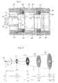
- 18 and 18 ' designate a floor which is shown during a programming phase ( 18 ) and at the time of disassembly ( 18' ).
- the projectile 18 is a programmable projectile with primary and secondary ballistics, which is equipped with an ejection charge and a time fuse and is filled with sub-projectiles 19 .
- a support tube 20 attached to the muzzle of the gun barrel 13 consists of three parts 21, 22, 23 . Between the first part 21 and the second or third part 22, 23 , ring coils 24, 25 are arranged for measuring the projectile speed. On the third part 23 — also called the programming part — a transmission coil 27 held in a coil body 26 is fastened. The type of attachment of the support tube 20 and the three parts 21, 22, 23 to each other is not shown and described. Lines 28, 29 are provided for supplying the ring coils. Soft iron bars 30 are arranged on the circumference of the support tube 20 for the purpose of shielding against magnetic fields which interfere with the measurement.
- the projectile 18 has a receiving coil 31 which is connected to a timer 34 via a filter 32 and a counter 33 .
- a pulse is generated in short succession in each ring coil.
- These pulses of the evaluation circuit 10 (Fig.1) are supplied, in which from the time interval of the pulses and a distance a between the toroid coils, the projectile velocity is calculated 24.25.
- a disassembly time is calculated, as described in more detail below, which is transmitted inductively in digital form to the receiving coil 31 when the projectile 18 passes through the transmitting coil 27 for the purpose of setting the counter 32 .
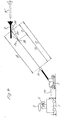
- Pz denotes a point of disassembly of the projectile 18 .
- the ejected subprojectiles are, depending on the distance from the point of decomposition Pz, evenly distributed on approximately semicircular curves of (perspectively represented) circular areas F1, F2, F3, F4 of a cone C.
- F1, F2, F3, F4 of a cone C.
- On a first abscissa the distance from the point of decomposition Pz is plotted in meters m, while on a second abscissa II the area sizes of the areas F1, F2, F3, F4 are plotted in square meters m 2 and their diameter in meters m.
- 4 and 4 ' denote the target to be defended, which is shown in a hit or shoot position ( 4 ) and in a position ( 4' ) preceding the hit or shoot position.
- the lead computation unit 9 calculates a target distance RT, a disassembly time Tz and a sub-projectile flight time ts from a predetermined disassembly distance Dz, a retention speed VOv and the target data Z, taking meteorological data into account for projectiles with primary and secondary ballistics.
- Tz is the flight time of the projectile to the point of disassembly Pz
- ts is the flight time of a subprojectile flying in the projectile direction from the point of disassembly Pz to the meeting point Pf ( Fig . 3,4 ).
- the lead speed VOv is formed, for example, from the mean value of a number of measured projectile speeds Vm supplied via the data transmission 17 , which immediately precede the current measured projectile speed Vm.
- the lead computing unit 9 also determines a gun angle a of the azimuth and a gun angle ⁇ of the elevation.
- the quantities ⁇ , ⁇ , Tz and VOv are fed to the correction computing unit 12 , which calculates a correction factor K as described in more detail below.
- the current (running) time (t) is interpolated or extrapolated.
- the ballistics of a projectile is determined by a system of differential equations of the form described, along with the initial conditions a clear ballistic solution is determined.
- ⁇ o ( t o ) With becomes a component of ⁇ o ( t o ) in the pipe direction and with ⁇ (2) / o defines a perpendicular component, so that is where means the speed of the pipe mouth and is a reserve size which is actually maintained by the projectile.
- the corrected decomposition time Tz (Vm) is interpolated or extrapolated depending on the validity for the current running time t.
- the disassembly time Tz (Vm, t) now calculated is supplied to the transmitter coil 27 of the programming part 23 of the measuring device 14 and, as already described above with reference to FIG. 2 , is transmitted inductively to a projectile 18 flying by.
- the disassembly distance Dz ( FIG. 3, 4 ) can be kept constant regardless of the variations in the projectile speed , and / or caused by the use of non-updated values, so that an optimal meeting or Probability of shooting can be achieved.
Landscapes
- Engineering & Computer Science (AREA)
- General Engineering & Computer Science (AREA)
- Chemical & Material Sciences (AREA)
- Aviation & Aerospace Engineering (AREA)
- Combustion & Propulsion (AREA)
- Aiming, Guidance, Guns With A Light Source, Armor, Camouflage, And Targets (AREA)
- Electrotherapy Devices (AREA)
- Control Of Ac Motors In General (AREA)
- Control Of Electric Motors In General (AREA)
- Generation Of Surge Voltage And Current (AREA)
- Investigating, Analyzing Materials By Fluorescence Or Luminescence (AREA)
- Fishing Rods (AREA)
- Testing Of Balance (AREA)
Applications Claiming Priority (3)
| Application Number | Priority Date | Filing Date | Title |
|---|---|---|---|
| CH1001/96 | 1996-04-19 | ||
| CH100196 | 1996-04-19 | ||
| CH100196 | 1996-04-19 |
Publications (2)
| Publication Number | Publication Date |
|---|---|
| EP0802391A1 EP0802391A1 (de) | 1997-10-22 |
| EP0802391B1 true EP0802391B1 (de) | 2000-12-13 |
Family
ID=4200143
Family Applications (1)
| Application Number | Title | Priority Date | Filing Date |
|---|---|---|---|
| EP96118044A Expired - Lifetime EP0802391B1 (de) | 1996-04-19 | 1996-11-11 | Verfahren zur Bestimmung einer korrigierten Zerlegungszeit eines programmierbar zerlegbaren Geschosses |
Country Status (12)
| Country | Link |
|---|---|
| US (1) | US5834675A (ko) |
| EP (1) | EP0802391B1 (ko) |
| JP (1) | JP3891619B2 (ko) |
| KR (1) | KR100410718B1 (ko) |
| AT (1) | ATE198103T1 (ko) |
| AU (1) | AU716346B2 (ko) |
| CA (1) | CA2190384C (ko) |
| DE (1) | DE59606214D1 (ko) |
| NO (1) | NO311954B1 (ko) |
| SG (1) | SG83658A1 (ko) |
| TR (1) | TR199600952A1 (ko) |
| ZA (1) | ZA969536B (ko) |
Families Citing this family (18)
| Publication number | Priority date | Publication date | Assignee | Title |
|---|---|---|---|---|
| FR2761767B1 (fr) * | 1997-04-03 | 1999-05-14 | Giat Ind Sa | Procede de programmation en vol d'un instant de declenchement d'un element de projectile, conduite de tir et fusee mettant en oeuvre un tel procede |
| EP0992762B1 (de) | 1998-10-08 | 2002-03-06 | Oerlikon Contraves Ag | Verfahren und Vorrichtung zur Übertragung von Informationen auf programmierbare Geschosse |
| DE59914323D1 (de) | 1998-10-08 | 2007-06-14 | Contraves Ag | Verfahren und Vorrichtung zur Korrektur der Zerlegungszeit bzw. der Zerlegungsumdrehungszahl eines drallstabilisierten programmierbaren Geschosses |
| ATE227839T1 (de) * | 1998-10-08 | 2002-11-15 | Contraves Pyrotec Ag | Verfahren zum korrigieren einer vorprogrammierten auslösung eines vorganges in einem drallstabilisierten geschoss, vorrichtung zur durchführung des verfahrens und verwendung der vorrichtung |
| US20040237762A1 (en) * | 1999-11-03 | 2004-12-02 | Metal Storm Limited | Set defence means |
| US6497170B1 (en) * | 2001-07-05 | 2002-12-24 | The United States Of America As Represented By The Secretary Of The Army | Muzzle brake vibration absorber |
| DE50309574D1 (de) * | 2003-02-26 | 2008-05-21 | Rwm Schweiz Ag | Verfahren zur Programmierung der Zerlegung von Projektilen und Rohrwaffen mit Programmiersystem |
| US7533612B1 (en) * | 2004-09-23 | 2009-05-19 | The United States Of America As Represented By The Secretary Of The Army | Projectile height of burst determination method and system |
| DE102009011447B9 (de) * | 2009-03-03 | 2012-08-16 | Diehl Bgt Defence Gmbh & Co. Kg | Verfahren zum Zünden eines Gefechtskopfs einer Granate und Fahrzeug |
| US11047663B1 (en) * | 2010-11-10 | 2021-06-29 | True Velocity Ip Holdings, Llc | Method of coding polymer ammunition cartridges |
| DE102011018248B3 (de) | 2011-04-19 | 2012-03-29 | Rheinmetall Air Defence Ag | Vorrichtung und Verfahren zur Programmierung eines Geschosses |
| DE102011106198B3 (de) * | 2011-06-07 | 2012-03-15 | Rheinmetall Air Defence Ag | Verfahren zur Bestimmung der Mündungsaustrittsgeschwindigkeit eines Projektils |
| US10514234B2 (en) | 2013-03-27 | 2019-12-24 | Nostromo Holdings, Llc | Method and apparatus for improving the aim of a weapon station, firing a point-detonating or an air-burst projectile |
| US11933585B2 (en) | 2013-03-27 | 2024-03-19 | Nostromo Holdings, Llc | Method and apparatus for improving the aim of a weapon station, firing a point-detonating or an air-burst projectile |
| EP2894429B1 (en) * | 2014-01-08 | 2018-08-15 | Nostromo Holdings, LLC | Mortar safety device |
| US9740326B2 (en) * | 2015-03-31 | 2017-08-22 | Synaptics Incorporated | Sensor array with split-drive differential sensing |
| FR3071596B1 (fr) * | 2017-09-27 | 2019-10-18 | Thales | Procede et dispositif de lancement de projectiles sur une cible a atteindre |
| US10883809B1 (en) * | 2019-05-07 | 2021-01-05 | U.S. Government As Represented By The Secretary Of The Army | Muzzle velocity correction |
Family Cites Families (17)
| Publication number | Priority date | Publication date | Assignee | Title |
|---|---|---|---|---|
| US4142442A (en) * | 1971-12-08 | 1979-03-06 | Avco Corporation | Digital fuze |
| US4267776A (en) * | 1979-06-29 | 1981-05-19 | Motorola, Inc. | Muzzle velocity compensating apparatus and method for a remote set fuze |
| US4449041A (en) * | 1980-10-03 | 1984-05-15 | Raytheon Company | Method of controlling antiaircraft fire |
| US4625646A (en) * | 1980-10-06 | 1986-12-02 | The Boeing Aerospace Company | Aerial missile having multiple submissiles with individual control of submissible ejection |
| FR2514884B1 (fr) * | 1981-10-20 | 1985-07-12 | Sfim | Procede et dispositif pour corriger globalement, d'un tir au suivant, le tir d'une arme a tir tendu |
| DE3309147A1 (de) * | 1983-03-15 | 1984-09-20 | Rainer Dipl.-Phys. 6901 Gaiberg Berthold | Verfahren und anordnung zur korrektur eines zuendzeitpunktes |
| US4799429A (en) * | 1984-03-30 | 1989-01-24 | Isc Technologies, Inc. | Programming circuit for individual bomblets in a cluster bomb |
| US4750423A (en) * | 1986-01-31 | 1988-06-14 | Loral Corporation | Method and system for dispensing sub-units to achieve a selected target impact pattern |
| FR2609165A1 (fr) * | 1986-12-31 | 1988-07-01 | Thomson Brandt Armements | Projectile comportant des sous-projectiles a zone d'efficacite predefinie |
| US4837718A (en) * | 1987-02-05 | 1989-06-06 | Lear Siegler, Inc. | Doppler radar method and apparatus for measuring a projectile's muzzle velocity |
| DE3862536D1 (de) * | 1987-07-20 | 1991-05-29 | Oerlikon Buehrle Ag | Vorrichtung zum digitalen einstellen eines zaehlers zum ausloesen eines zeitzuenders in einem geschoss. |
| GB2226624B (en) * | 1987-12-12 | 1991-07-03 | Thorn Emi Electronics Ltd | Projectile |
| DE3830518A1 (de) * | 1988-09-08 | 1990-03-22 | Rheinmetall Gmbh | Vorrichtung zur einstellung eines geschosszeitzuenders |
| DE59100529D1 (de) * | 1990-07-19 | 1993-12-02 | Contraves Ag | Empfangsspule für einen programmierbaren Geschosszünder. |
| CA2082448C (en) * | 1991-05-08 | 2002-04-30 | Christopher Robert Gent | Weapons systems |
| US5267502A (en) * | 1991-05-08 | 1993-12-07 | Sd-Scicon Uk Limited | Weapons systems future muzzle velocity neural network |
| US5497704A (en) * | 1993-12-30 | 1996-03-12 | Alliant Techsystems Inc. | Multifunctional magnetic fuze |
-
1996
- 1996-11-08 NO NO19964757A patent/NO311954B1/no not_active IP Right Cessation
- 1996-11-11 DE DE59606214T patent/DE59606214D1/de not_active Expired - Lifetime
- 1996-11-11 AT AT96118044T patent/ATE198103T1/de active
- 1996-11-11 EP EP96118044A patent/EP0802391B1/de not_active Expired - Lifetime
- 1996-11-13 ZA ZA969536A patent/ZA969536B/xx unknown
- 1996-11-13 AU AU71727/96A patent/AU716346B2/en not_active Ceased
- 1996-11-13 SG SG9611114A patent/SG83658A1/en unknown
- 1996-11-14 CA CA002190384A patent/CA2190384C/en not_active Expired - Fee Related
- 1996-11-14 US US08/749,329 patent/US5834675A/en not_active Expired - Lifetime
- 1996-11-18 KR KR1019960054801A patent/KR100410718B1/ko not_active IP Right Cessation
- 1996-11-25 JP JP31345596A patent/JP3891619B2/ja not_active Expired - Fee Related
- 1996-11-27 TR TR96/00952A patent/TR199600952A1/xx unknown
Also Published As
| Publication number | Publication date |
|---|---|
| JPH09287899A (ja) | 1997-11-04 |
| US5834675A (en) | 1998-11-10 |
| EP0802391A1 (de) | 1997-10-22 |
| TR199600952A1 (xx) | 1997-11-21 |
| NO964757L (no) | 1997-10-20 |
| NO311954B1 (no) | 2002-02-18 |
| ATE198103T1 (de) | 2000-12-15 |
| DE59606214D1 (de) | 2001-01-18 |
| CA2190384A1 (en) | 1997-10-20 |
| JP3891619B2 (ja) | 2007-03-14 |
| CA2190384C (en) | 2003-09-30 |
| SG83658A1 (en) | 2001-10-16 |
| NO964757D0 (no) | 1996-11-08 |
| KR100410718B1 (ko) | 2004-04-03 |
| AU7172796A (en) | 1997-10-23 |
| KR970070943A (ko) | 1997-11-07 |
| ZA969536B (en) | 1997-06-17 |
| AU716346B2 (en) | 2000-02-24 |
Similar Documents
| Publication | Publication Date | Title |
|---|---|---|
| EP0802391B1 (de) | Verfahren zur Bestimmung einer korrigierten Zerlegungszeit eines programmierbar zerlegbaren Geschosses | |
| EP0802392B1 (de) | Verfahren und Vorrichtung zur Bestimmung einer korrigierten Zerlegungszeit eines programmierbar zerlegbaren Geschosses | |
| EP0118122B1 (de) | Verfahren und Vorrichtung zur Einstellung der Laufzeit eines Geschoss-Zeitzünders | |
| EP0802390B1 (de) | Verfahren zur Bestimmung einer korrigierten Zerlegungszeit eines programmierbar zerlegbaren Geschosses | |
| DE2605374B2 (de) | Vorrichtung zum digitalen Einstellen eines Zählers zum Auslösen eines Zeitzünders in einem GeschoS | |
| EP0769673B1 (de) | Verfahren und Vorrichtung zum Programmieren von Zeitzündern von Geschossen | |
| DE2347374C2 (de) | Abstandszünder für einen Gefechtskopf | |
| DE2423704A1 (de) | Verzoegerungszuender fuer geschosse | |
| EP1482311B1 (de) | Vorrichtung und Verfahren zur Ermittlung der Mündungsgeschwindigkeit eines Projektils | |
| DE2452586C3 (de) | Verfahren und Vorrichtung zur Festlegung der Dauer des Flugweges eines Geschosses | |
| EP2699871B1 (de) | Vorrichtung und verfahren zur programmierung eines geschosses | |
| DE1623362C3 (de) | Einrichtung zum Zünden einer Sprengladung bzw. zum Auslosen einer Funktion | |
| EP0992758B1 (de) | Verfahren und Vorrichtung zur Korrektur der Zerlegungszeit bzw. der Zerlegungsumdrehungszahl eines drallstabilisierten programmierbaren Geschosses | |
| EP0992761B1 (de) | Verfahren zum Korrigieren einer vorprogrammierten Auslösung eines Vorganges in einem drallstabilisierten Geschoss, Vorrichtung zur Durchführung des Verfahrens und Verwendung der Vorrichtung | |
| EP0992762B1 (de) | Verfahren und Vorrichtung zur Übertragung von Informationen auf programmierbare Geschosse | |
| DE60219564T2 (de) | Verfahren zum Einstellen eines Geschosszünders, Programmiereinrichtung und Zeitzünder die in einen solchem Verfahren verwendet werden | |
| CH656453A5 (en) | Device for firing simulation using light pulses | |
| DE102011106198B3 (de) | Verfahren zur Bestimmung der Mündungsaustrittsgeschwindigkeit eines Projektils | |
| DE3716450C1 (en) | Setting electronic timer for munition detonator - entering type, temp. of drive charge weather and target data in fuse ignition computer | |
| DE3925000C1 (de) | Verfahren zur Vorgabe einer Geschoß-Laufzeit und Vorrichtung zur Durchführung dieses Verfahrens | |
| EP2226607A2 (de) | Verfahren zum Zünden eines Gefechtskopfs einer Granate und Fahrzeug | |
| DE3903802C2 (ko) | ||
| EP0348985A2 (de) | Zündeinrichtung für Sprenggeschosse | |
| DE10028746A1 (de) | Verfahren und Vorrichtung zur Bestimmung der Zündverzugszeit bei zielverfolgenden Lenkflugkörpern | |
| DE3127844C2 (de) | Verfahen zum Abwerfen von Munition von einem Kampfflugzeug aus |
Legal Events
| Date | Code | Title | Description |
|---|---|---|---|
| PUAI | Public reference made under article 153(3) epc to a published international application that has entered the european phase |
Free format text: ORIGINAL CODE: 0009012 |
|
| AK | Designated contracting states |
Kind code of ref document: A1 Designated state(s): AT BE CH DE FR GB IT LI NL SE |
|
| 17P | Request for examination filed |
Effective date: 19971211 |
|
| 17Q | First examination report despatched |
Effective date: 19990526 |
|
| RTI1 | Title (correction) |
Free format text: METHOD OF IDENTIFYING A CORRECTED DISINTEGRATION TIME OF A PROGRAMMABLE AND FRANGIBLE PROJECTILE |
|
| RAP1 | Party data changed (applicant data changed or rights of an application transferred) |
Owner name: OERLIKON CONTRAVES AG |
|
| GRAG | Despatch of communication of intention to grant |
Free format text: ORIGINAL CODE: EPIDOS AGRA |
|
| GRAG | Despatch of communication of intention to grant |
Free format text: ORIGINAL CODE: EPIDOS AGRA |
|
| GRAH | Despatch of communication of intention to grant a patent |
Free format text: ORIGINAL CODE: EPIDOS IGRA |
|
| GRAH | Despatch of communication of intention to grant a patent |
Free format text: ORIGINAL CODE: EPIDOS IGRA |
|
| GRAA | (expected) grant |
Free format text: ORIGINAL CODE: 0009210 |
|
| AK | Designated contracting states |
Kind code of ref document: B1 Designated state(s): AT BE CH DE FR GB IT LI NL SE |
|
| REF | Corresponds to: |
Ref document number: 198103 Country of ref document: AT Date of ref document: 20001215 Kind code of ref document: T |
|
| REG | Reference to a national code |
Ref country code: CH Ref legal event code: EP |
|
| REG | Reference to a national code |
Ref country code: CH Ref legal event code: NV Representative=s name: OK PAT AG |
|
| REF | Corresponds to: |
Ref document number: 59606214 Country of ref document: DE Date of ref document: 20010118 |
|
| GBT | Gb: translation of ep patent filed (gb section 77(6)(a)/1977) |
Effective date: 20010112 |
|
| ET | Fr: translation filed | ||
| ITF | It: translation for a ep patent filed |
Owner name: FUMERO BREVETTI S.N.C. |
|
| PLBE | No opposition filed within time limit |
Free format text: ORIGINAL CODE: 0009261 |
|
| STAA | Information on the status of an ep patent application or granted ep patent |
Free format text: STATUS: NO OPPOSITION FILED WITHIN TIME LIMIT |
|
| 26N | No opposition filed | ||
| REG | Reference to a national code |
Ref country code: GB Ref legal event code: IF02 |
|
| PGFP | Annual fee paid to national office [announced via postgrant information from national office to epo] |
Ref country code: AT Payment date: 20101112 Year of fee payment: 15 |
|
| PGFP | Annual fee paid to national office [announced via postgrant information from national office to epo] |
Ref country code: GB Payment date: 20101118 Year of fee payment: 15 |
|
| REG | Reference to a national code |
Ref country code: DE Ref legal event code: R082 Ref document number: 59606214 Country of ref document: DE Representative=s name: THUL PATENTANWALTSGESELLSCHAFT MBH, DE |
|
| REG | Reference to a national code |
Ref country code: DE Ref legal event code: R084 Ref document number: 59606214 Country of ref document: DE Effective date: 20111019 |
|
| PGFP | Annual fee paid to national office [announced via postgrant information from national office to epo] |
Ref country code: BE Payment date: 20111110 Year of fee payment: 16 |
|
| REG | Reference to a national code |
Ref country code: DE Ref legal event code: R082 Ref document number: 59606214 Country of ref document: DE Representative=s name: THUL PATENTANWALTSGESELLSCHAFT MBH, DE |
|
| REG | Reference to a national code |
Ref country code: DE Ref legal event code: R082 Ref document number: 59606214 Country of ref document: DE Representative=s name: THUL PATENTANWALTSGESELLSCHAFT MBH, DE Effective date: 20111229 Ref country code: DE Ref legal event code: R082 Ref document number: 59606214 Country of ref document: DE Representative=s name: THUL PATENTANWALTSGESELLSCHAFT MBH, DE Effective date: 20120523 Ref country code: DE Ref legal event code: R081 Ref document number: 59606214 Country of ref document: DE Owner name: RHEINMETALL AIR DEFENCE AG, CH Free format text: FORMER OWNER: OERLIKON CONTRAVES AG, ZUERICH, CH Effective date: 20120523 Ref country code: DE Ref legal event code: R081 Ref document number: 59606214 Country of ref document: DE Owner name: RHEINMETALL AIR DEFENCE AG, CH Free format text: FORMER OWNER: OERLIKON-CONTRAVES AG, ZUERICH, CH Effective date: 20111229 |
|
| BERE | Be: lapsed |
Owner name: *OERLIKON CONTRAVES A.G. Effective date: 20121130 |
|
| REG | Reference to a national code |
Ref country code: AT Ref legal event code: MM01 Ref document number: 198103 Country of ref document: AT Kind code of ref document: T Effective date: 20121111 |
|
| GBPC | Gb: european patent ceased through non-payment of renewal fee |
Effective date: 20121111 |
|
| PG25 | Lapsed in a contracting state [announced via postgrant information from national office to epo] |
Ref country code: AT Free format text: LAPSE BECAUSE OF NON-PAYMENT OF DUE FEES Effective date: 20121111 |
|
| PG25 | Lapsed in a contracting state [announced via postgrant information from national office to epo] |
Ref country code: BE Free format text: LAPSE BECAUSE OF NON-PAYMENT OF DUE FEES Effective date: 20121130 |
|
| PG25 | Lapsed in a contracting state [announced via postgrant information from national office to epo] |
Ref country code: GB Free format text: LAPSE BECAUSE OF NON-PAYMENT OF DUE FEES Effective date: 20121111 |
|
| PGFP | Annual fee paid to national office [announced via postgrant information from national office to epo] |
Ref country code: DE Payment date: 20141119 Year of fee payment: 19 Ref country code: CH Payment date: 20141119 Year of fee payment: 19 Ref country code: FR Payment date: 20141119 Year of fee payment: 19 Ref country code: SE Payment date: 20141119 Year of fee payment: 19 |
|
| PGFP | Annual fee paid to national office [announced via postgrant information from national office to epo] |
Ref country code: NL Payment date: 20141119 Year of fee payment: 19 |
|
| PGFP | Annual fee paid to national office [announced via postgrant information from national office to epo] |
Ref country code: IT Payment date: 20141125 Year of fee payment: 19 |
|
| REG | Reference to a national code |
Ref country code: DE Ref legal event code: R119 Ref document number: 59606214 Country of ref document: DE |
|
| REG | Reference to a national code |
Ref country code: CH Ref legal event code: PL |
|
| PG25 | Lapsed in a contracting state [announced via postgrant information from national office to epo] |
Ref country code: CH Free format text: LAPSE BECAUSE OF NON-PAYMENT OF DUE FEES Effective date: 20151130 Ref country code: IT Free format text: LAPSE BECAUSE OF NON-PAYMENT OF DUE FEES Effective date: 20151111 Ref country code: LI Free format text: LAPSE BECAUSE OF NON-PAYMENT OF DUE FEES Effective date: 20151130 |
|
| REG | Reference to a national code |
Ref country code: NL Ref legal event code: MM Effective date: 20151201 |
|
| REG | Reference to a national code |
Ref country code: FR Ref legal event code: ST Effective date: 20160729 |
|
| PG25 | Lapsed in a contracting state [announced via postgrant information from national office to epo] |
Ref country code: SE Free format text: LAPSE BECAUSE OF NON-PAYMENT OF DUE FEES Effective date: 20151112 |
|
| PG25 | Lapsed in a contracting state [announced via postgrant information from national office to epo] |
Ref country code: NL Free format text: LAPSE BECAUSE OF NON-PAYMENT OF DUE FEES Effective date: 20151201 |
|
| PG25 | Lapsed in a contracting state [announced via postgrant information from national office to epo] |
Ref country code: DE Free format text: LAPSE BECAUSE OF NON-PAYMENT OF DUE FEES Effective date: 20160601 |
|
| PG25 | Lapsed in a contracting state [announced via postgrant information from national office to epo] |
Ref country code: FR Free format text: LAPSE BECAUSE OF NON-PAYMENT OF DUE FEES Effective date: 20151130 |