EP0802391B1 - Method of identifying a corrected disintegration time of a programmable and frangible projectile - Google Patents
Method of identifying a corrected disintegration time of a programmable and frangible projectile Download PDFInfo
- Publication number
- EP0802391B1 EP0802391B1 EP96118044A EP96118044A EP0802391B1 EP 0802391 B1 EP0802391 B1 EP 0802391B1 EP 96118044 A EP96118044 A EP 96118044A EP 96118044 A EP96118044 A EP 96118044A EP 0802391 B1 EP0802391 B1 EP 0802391B1
- Authority
- EP
- European Patent Office
- Prior art keywords
- projectile
- velocity
- time
- target
- fragmentation
- Prior art date
- Legal status (The legal status is an assumption and is not a legal conclusion. Google has not performed a legal analysis and makes no representation as to the accuracy of the status listed.)
- Expired - Lifetime
Links
- 238000000034 method Methods 0.000 title claims description 4
- 230000001133 acceleration Effects 0.000 claims description 7
- 238000004364 calculation method Methods 0.000 claims description 2
- 238000013467 fragmentation Methods 0.000 claims 9
- 238000006062 fragmentation reaction Methods 0.000 claims 9
- 238000003780 insertion Methods 0.000 claims 1
- 230000037431 insertion Effects 0.000 claims 1
- 238000000354 decomposition reaction Methods 0.000 description 6
- 238000011156 evaluation Methods 0.000 description 6
- 230000005540 biological transmission Effects 0.000 description 4
- XEEYBQQBJWHFJM-UHFFFAOYSA-N Iron Chemical compound [Fe] XEEYBQQBJWHFJM-UHFFFAOYSA-N 0.000 description 2
- 238000009795 derivation Methods 0.000 description 2
- 238000001514 detection method Methods 0.000 description 2
- 238000005259 measurement Methods 0.000 description 2
- 241001136792 Alle Species 0.000 description 1
- 230000007423 decrease Effects 0.000 description 1
- 238000010586 diagram Methods 0.000 description 1
- 230000004907 flux Effects 0.000 description 1
- 229910052742 iron Inorganic materials 0.000 description 1
- 230000014759 maintenance of location Effects 0.000 description 1
- 239000011159 matrix material Substances 0.000 description 1
Images

Classifications
-
- F—MECHANICAL ENGINEERING; LIGHTING; HEATING; WEAPONS; BLASTING
- F42—AMMUNITION; BLASTING
- F42B—EXPLOSIVE CHARGES, e.g. FOR BLASTING, FIREWORKS, AMMUNITION
- F42B15/00—Self-propelled projectiles or missiles, e.g. rockets; Guided missiles
-
- F—MECHANICAL ENGINEERING; LIGHTING; HEATING; WEAPONS; BLASTING
- F42—AMMUNITION; BLASTING
- F42C—AMMUNITION FUZES; ARMING OR SAFETY MEANS THEREFOR
- F42C17/00—Fuze-setting apparatus
- F42C17/04—Fuze-setting apparatus for electric fuzes
Definitions
- the invention relates to a method for determining a corrected disassembly time one of a programmable disassembled from a gun barrel Projectile according to the preamble of the only claim.
- a device which has a measuring device for the projectile velocity arranged at the mouth of a gun barrel.
- the measuring device consists of two ring coils arranged at a certain distance from one another.
- a pulse is generated in short succession in each ring coil due to the change in magnetic flux that occurs.
- the pulses are fed to evaluation electronics, in which the projectile speed is calculated from the time interval between the pulses and the distance between the ring coils.
- a transmitting coil is arranged behind the measuring device for the speed, which co-operates with a receiving coil provided in the projectile.
- the receiving coil is connected to a counter via a high-pass filter, which is connected on the output side to a timer.
- a disassembly time is formed from the calculated bullet speed and a target distance to a target object, which is transmitted inductively to the bullet immediately after the measuring device has flown through. With this disassembly time, the time fuse is set so that the projectile can be disassembled in the area of the target object.
- an attacking target can be destroyed by multiple hits, as is known, for example, from a publication OC 2052 d 94 from the company Oerlikon-Contraves, Zurich, if, after the sub-projectiles have been ejected, Time of disassembly the expected area of the target is occupied by a cloud formed by the subprojectiles.
- the part carrying the subprojectiles is separated and torn open at predetermined breaking points.
- the ejected sub-projectiles describe a swirl-stabilized trajectory caused by the rotation of the projectile and lie evenly distributed on approximately semicircular curves of circular areas of a cone, so that a good chance of hitting can be achieved.
- the invention has for its object to propose a method according to the preamble, by means of which an optimal while avoiding the disadvantages mentioned above Hit or shot probability is achievable.
- the advantages achieved with the invention can be seen in the fact that a given disassembly distance is independent of the current measured bullet speed, so that a permanent optimal hit or shot probability is achieved can.
- the proposed correction factor for correcting the disassembly time is based only on the relative velocity of the bullet-target and a derivation of the ballistics at the meeting point.
- 1 denotes a fire control and 2 a gun.
- the fire control system 1 consists of a search sensor 3 for the detection of a target 4 , a follow-up sensor 5 connected to the search sensor 3 for target detection, 3-D target tracking and 3-D target measurement, and a fire control computer 6 .
- the fire control computer 6 has at least one main filter 7 , a lead computing unit 9 and a correction computing unit 12 .
- the main filter 7 is connected on the input side to the follow sensor 5 and on the output side to the lead computing unit 9 , the main filter 7 receiving the 3-D target data received from the follow sensor 5 in the form of estimated target data 2 such as position, speed, acceleration, etc. forward the lead computing unit 9 , which is connected on the output side to the correction computing unit.
- Meteorological data can be supplied to the lead computing unit 9 via a further input Me. The meaning of the designations on the individual connections or connections is explained in more detail below on the basis of the functional description.
- a computer of the gun 2 has an evaluation circuit 10 and an update computing unit 11 .
- the evaluation circuit 10 is connected on the input side to a measuring device 14 for the projectile speed, which is arranged at the mouth of a gun barrel 13 and is described in greater detail below with reference to FIG . 2 , and is connected on the output side to the lead computing unit 9 and the update computing unit 11 .
- the update computing unit 11 is connected on the input side to the reserve and correction computing unit 9, 12 and is connected on the output side to a programming part integrated in the measuring device 14 .
- the correction arithmetic unit 12 is connected on the input side to the lead arithmetic unit 9 and on the output side to the update arithmetic unit 11 .
- a gun servo 15 and a triggering device 16 responding to a fire command are also connected to the lead computing unit 9 .
- the connections between the fire control 1 and the gun 2 are combined to form a data transmission, which is designated by 17 .
- the meaning of the designations on the individual connections between the computing units 10, 11, 12 and between the fire control system 1 and the gun 2 is explained in more detail below on the basis of the functional description.
- 18 and 18 ' designate a floor which is shown during a programming phase ( 18 ) and at the time of disassembly ( 18' ).
- the projectile 18 is a programmable projectile with primary and secondary ballistics, which is equipped with an ejection charge and a time fuse and is filled with sub-projectiles 19 .
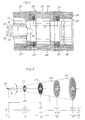
- a support tube 20 attached to the muzzle of the gun barrel 13 consists of three parts 21, 22, 23 . Between the first part 21 and the second or third part 22, 23 , ring coils 24, 25 are arranged for measuring the projectile speed. On the third part 23 — also called the programming part — a transmission coil 27 held in a coil body 26 is fastened. The type of attachment of the support tube 20 and the three parts 21, 22, 23 to each other is not shown and described. Lines 28, 29 are provided for supplying the ring coils. Soft iron bars 30 are arranged on the circumference of the support tube 20 for the purpose of shielding against magnetic fields which interfere with the measurement.
- the projectile 18 has a receiving coil 31 which is connected to a timer 34 via a filter 32 and a counter 33 .
- a pulse is generated in short succession in each ring coil.
- These pulses of the evaluation circuit 10 (Fig.1) are supplied, in which from the time interval of the pulses and a distance a between the toroid coils, the projectile velocity is calculated 24.25.
- a disassembly time is calculated, as described in more detail below, which is transmitted inductively in digital form to the receiving coil 31 when the projectile 18 passes through the transmitting coil 27 for the purpose of setting the counter 32 .
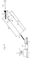
- Pz denotes a point of disassembly of the projectile 18 .
- the ejected subprojectiles are, depending on the distance from the point of decomposition Pz, evenly distributed on approximately semicircular curves of (perspectively represented) circular areas F1, F2, F3, F4 of a cone C.
- F1, F2, F3, F4 of a cone C.
- On a first abscissa the distance from the point of decomposition Pz is plotted in meters m, while on a second abscissa II the area sizes of the areas F1, F2, F3, F4 are plotted in square meters m 2 and their diameter in meters m.
- 4 and 4 ' denote the target to be defended, which is shown in a hit or shoot position ( 4 ) and in a position ( 4' ) preceding the hit or shoot position.
- the lead computation unit 9 calculates a target distance RT, a disassembly time Tz and a sub-projectile flight time ts from a predetermined disassembly distance Dz, a retention speed VOv and the target data Z, taking meteorological data into account for projectiles with primary and secondary ballistics.
- Tz is the flight time of the projectile to the point of disassembly Pz
- ts is the flight time of a subprojectile flying in the projectile direction from the point of disassembly Pz to the meeting point Pf ( Fig . 3,4 ).
- the lead speed VOv is formed, for example, from the mean value of a number of measured projectile speeds Vm supplied via the data transmission 17 , which immediately precede the current measured projectile speed Vm.
- the lead computing unit 9 also determines a gun angle a of the azimuth and a gun angle ⁇ of the elevation.
- the quantities ⁇ , ⁇ , Tz and VOv are fed to the correction computing unit 12 , which calculates a correction factor K as described in more detail below.
- the current (running) time (t) is interpolated or extrapolated.
- the ballistics of a projectile is determined by a system of differential equations of the form described, along with the initial conditions a clear ballistic solution is determined.
- ⁇ o ( t o ) With becomes a component of ⁇ o ( t o ) in the pipe direction and with ⁇ (2) / o defines a perpendicular component, so that is where means the speed of the pipe mouth and is a reserve size which is actually maintained by the projectile.
- the corrected decomposition time Tz (Vm) is interpolated or extrapolated depending on the validity for the current running time t.
- the disassembly time Tz (Vm, t) now calculated is supplied to the transmitter coil 27 of the programming part 23 of the measuring device 14 and, as already described above with reference to FIG. 2 , is transmitted inductively to a projectile 18 flying by.
- the disassembly distance Dz ( FIG. 3, 4 ) can be kept constant regardless of the variations in the projectile speed , and / or caused by the use of non-updated values, so that an optimal meeting or Probability of shooting can be achieved.
Landscapes
- Engineering & Computer Science (AREA)
- General Engineering & Computer Science (AREA)
- Chemical & Material Sciences (AREA)
- Aviation & Aerospace Engineering (AREA)
- Combustion & Propulsion (AREA)
- Aiming, Guidance, Guns With A Light Source, Armor, Camouflage, And Targets (AREA)
- Control Of Electric Motors In General (AREA)
- Control Of Ac Motors In General (AREA)
- Electrotherapy Devices (AREA)
- Generation Of Surge Voltage And Current (AREA)
- Investigating, Analyzing Materials By Fluorescence Or Luminescence (AREA)
- Testing Of Balance (AREA)
- Fishing Rods (AREA)
Abstract
Description
Die Erfindung betrifft ein Verfahren zur Bestimmung einer korrigierten Zerlegungszeit eines eines aus einem Geschützrohr abgeschossenen programmierbar zerlegbaren Geschosses nach dem Oberbegriff des einzigen Anspruchs.The invention relates to a method for determining a corrected disassembly time one of a programmable disassembled from a gun barrel Projectile according to the preamble of the only claim.
Mit der europäischen Patentanmeldung 0 300 255 ist eine Vorrichtung bekannt geworden, die eine an der Mündung eines Geschützrohres angeordnete Messvorrichtung für die Geschossgeschwindigkeit aufweist. Die Messvorrichtung besteht aus zwei in einem bestimmten Abstand voneinander angeordneten Ringspulen. Beim Durchgang eines Geschosses durch die beiden Ringspulen wird aufgrund der dabei auftretenden Aenderung des magnetischen Flusses kurz hintereinander in jeder Ringspule ein Impuls erzeugt. Die Impulse werden einer Auswerteelektronik zugeführt, in welcher aus dem zeitlichen Abstand der Impulse und dem Abstand zwischen den Ringspulen die Geschossgeschwindigkeit errechnet wird. In Bewegungsrichtung des Geschosses ist hinter der Messvorrichtung für die Geschwindigkeit eine Sendespule angeordnet, die mit einer im Geschoss vorgesehenen Empfangsspule zusammenwirkt. Die Empfangsspule ist über ein Hochpassfilter mit einem Zähler verbunden, der ausgangsseitig mit einem Zeitzünder in Verbindung steht. Aus der errechneten Geschossgeschwindigkeit und einer aus Sensordaten ermittelten Treffdistanz zu einem Zielobjekt wird eine Zerlegungszeit gebildet, die unmittelbar nach dem Durchfliegen der Messvorrichtung induktiv auf das Geschoss übertragen wird. Mit dieser Zerlegungszeit wird der Zeitzünder eingestellt, so dass das Geschoss im Bereiche des Zielobjektes zerlegt werden kann.With the European patent application 0 300 255 a device has become known which has a measuring device for the projectile velocity arranged at the mouth of a gun barrel. The measuring device consists of two ring coils arranged at a certain distance from one another. When a bullet passes through the two ring coils, a pulse is generated in short succession in each ring coil due to the change in magnetic flux that occurs. The pulses are fed to evaluation electronics, in which the projectile speed is calculated from the time interval between the pulses and the distance between the ring coils. In the direction of movement of the projectile, a transmitting coil is arranged behind the measuring device for the speed, which co-operates with a receiving coil provided in the projectile. The receiving coil is connected to a counter via a high-pass filter, which is connected on the output side to a timer. A disassembly time is formed from the calculated bullet speed and a target distance to a target object, which is transmitted inductively to the bullet immediately after the measuring device has flown through. With this disassembly time, the time fuse is set so that the projectile can be disassembled in the area of the target object.
Werden Geschosse mit Subprojektilen verwendet (Munition mit Primär- und Sekundärballistik), so kann wie beispielsweise aus einer Druckschrift OC 2052 d 94 der Firma Oerlikon-Contraves, Zürich, bekannt, ein angreifendes Ziel durch mehrfache Treffer zerstört werden, wenn nach Ausstossen der Subprojektile im Zerlegungszeitpunkt das Erwartungsgebiet des Zieles von einer durch die Subprojektile gebildeten Wolke belegt ist. Bei der Zerlegung eines solchen Geschosses wird der die Subprojektile tragende Teil abgetrennt und an Sollbruchstellen aufgerissen. Die ausgestossenen Subprojektile beschreiben eine durch die Rotation des Geschosses hervorgerufene drallstabilisierte Flugbahn und liegen gleichmässig verteilt auf annähernd halbkreisförmigen Kurven von Kreisflächen eines Kegels, so dass eine gute Treffwahrscheinlichkeit erreicht werden kann.If projectiles with sub-projectiles are used (ammunition with primary and secondary ballistics), an attacking target can be destroyed by multiple hits, as is known, for example, from a publication OC 2052 d 94 from the company Oerlikon-Contraves, Zurich, if, after the sub-projectiles have been ejected, Time of disassembly the expected area of the target is occupied by a cloud formed by the subprojectiles. When dismantling such a projectile, the part carrying the subprojectiles is separated and torn open at predetermined breaking points. The ejected sub-projectiles describe a swirl-stabilized trajectory caused by the rotation of the projectile and lie evenly distributed on approximately semicircular curves of circular areas of a cone, so that a good chance of hitting can be achieved.
Bei vorstehend beschriebener Vorrichtung kann durch Streuungen in der Zerlegungsdistanz, die beispielsweise durch Streuungen der Geschossgeschwindigkeit und/oder Verwendung nicht aktualisierter Werte verursacht werden, nicht in jedem Fall eine gute Treff-bzw. Abschusswahrscheinlichkeit erreicht werden. Bei grösseren Zerlegungsdistanzen würde wohl die Kreisfläche grösser, die Dichte der Subprojektile jedoch kleiner werden. Bei kleineren Zerlegungsdistanzen tritt der umgekehrte Fall ein: Die Dichte der Subprojektile wäre grösser, die Kreisfläche jedoch kleiner.In the device described above, scattering in the disassembly distance, which, for example, by scattering the bullet speed and / or use not updated values are caused, not always a good meeting or Probability of being shot down. With larger disassembly distances the circular area would probably be larger, but the density of the subprojectiles would be smaller. The reverse occurs with smaller disassembly distances: the density of the subprojectiles would be larger, but the circular area would be smaller.
Der Erfindung liegt die Aufgabe zugrunde ein Verfahren gemäss Oberbegriff vorzuschlagen, mittels welchen unter Vermeidung vorstehend erwähnter Nachteile eine optimale Treff- bzw. Abschusswahrscheinlichkeit erreichbar ist.The invention has for its object to propose a method according to the preamble, by means of which an optimal while avoiding the disadvantages mentioned above Hit or shot probability is achievable.
Diese Aufgabe wird durch die im einzigen Patentanspruch angegebene Erfindung gelöst. Hierbei wird eine gegebene optimale Zerlegungsdistanz zwischen einem Zerlegungspunkt des Geschosses und einem Treffpunkt des Zieles durch Korrektur der Zerlegungszeit des Geschosses gleichbleibend gehalten. Die Korrek-tur erfolgt indem zur Zerlegungszeit ein mit einer Geschwindigkeitsdifferenz multiplizierter Korrekturfaktor addiert wird. Die Geschwindigkeitsdifferenz wird aus der Differenz der aktuellen gemessenen Geschossgeschwindigkeit und einer Vorhaltgeschwindigkeit des Geschosses gebildet, wobei die Vorhaltgeschwindigkeit aus dem Mittelwert einer Anzahl vorhergehender, aufeinanderfolgender Geschossgeschwindigkeiten errechnet wird.This object is achieved by the invention specified in the single patent claim. Here a given optimal decomposition distance between a decomposition point of the Floor and a meeting point of the target by correcting the disassembly time of the Projectile kept constant. The correction takes place at the disassembly time correction factor multiplied by a speed difference is added. The speed difference is the difference between the current measured bullet speed and a lead rate of the projectile, the Lead speed from the mean of a number of previous, successive ones Floor speeds is calculated.
Die mit der Erfindung erzielten Vorteile sind darin zu sehen, dass eine gegebene Zerlegungsdistanz von der aktuellen gemessenen Geschossgeschwindigkeit unabhängig ist, so dass eine dauernde optimale Treff- bzw. Abschusswahrscheinlichkeit erzielt werden kann. Der vorgeschlagene Korrekturfaktor für die Korrektur der Zerlegungszeit basiert lediglich auf der relativen Geschwindigkeit Geschoss-Ziel und einer Ableitung der Ballistik im Treffpunkt.The advantages achieved with the invention can be seen in the fact that a given disassembly distance is independent of the current measured bullet speed, so that a permanent optimal hit or shot probability is achieved can. The proposed correction factor for correcting the disassembly time is based only on the relative velocity of the bullet-target and a derivation of the ballistics at the meeting point.
Im folgenden wird die Erfindung anhand eines Ausführungsbeispieles im Zusammenhang mit der Zeichnung näher erläutert. Es zeigen.
- Fig.1
- eine schematische Darstellung eines Waffensteuerungs-Systems mit der er findungsgemässen Vorrichtung,
- Fig.2
- einen Längsschnitt durch eine Mess- und Programmiervorrichtung,
- Fig.3
- ein Diagramm der Verteilung von Subprojektilen in Abhängigkeit von der Zer legungsdistanz, und
- Fig.4
- eine andere Darstellung des Waffensteuerungs-Systems gemäss Fig.1.
- Fig. 1
- 1 shows a schematic illustration of a weapon control system with the device according to the invention,
- Fig. 2
- a longitudinal section through a measuring and programming device,
- Fig. 3
- a diagram of the distribution of subprojectiles depending on the decomposition distance, and
- Fig. 4
- another representation of the weapon control system according to Fig.1 .
In der Fig.1 ist mit 1 eine Feuerleitung und mit 2 ein Geschütz bezeichnet. Die Feuerleitung
1 besteht aus einem Suchsensor 3 für die Entdeckung eines Zieles 4, einem mit
dem Suchsensor 3 verbundenen Folgesensor 5 für die Zielerfassung, die 3-D-Zielverfolgung
und die 3-D-Zielvermessung, sowie einem Feuerleitungsrechner 6. Der Feuerleitungsrechner
6 weist mindestens ein Hauptfilter 7, eine Vorhalt-Recheneinheit 9 und eine
Korrektur-Recheneinheit 12 auf. Das Hauptfilter 7 ist eingangsseitig mit dem Folgesensor
5 und ausgangsseitig mit der Vorhalt-Recheneinheit 9 verbunden, wobei das Haupt-filter
7 die vom Folgesensor 5 empfangenen 3-D-Zieldaten in Form von geschätzten Zieldaten
2 wie Position, Geschwindigkeit, Beschleunigung usw. an die Vorhalt-Recheneinheit 9
weiterleitet, die ausgangsseitig mit der Korrektur-Recheneinheit in Verbindung steht.
Ueber einen weiteren Eingang Me können der Vorhalt-Recheneinheit 9 meteorologische
Daten zugeführt werden. Die Bedeutung der Bezeichnungen an den einzelnen Verbindungen
bzw. Anschlüssen wird nachstehend anhand der Funktionsbeschreibung
näher erläutert. In Figure 1, 1 denotes a fire control and 2 a gun. The fire control system 1 consists of a
Ein Rechner des Geschützes 2 weist eine Auswerteschaltung 10 und eine Aufdatierungs-Recheneinheit
11 auf. Die Auswerteschaltung 10 ist eingangsseitig an einer an der Mündung
eines Geschützrohres 13 angeordneten, nachstehend anhand der Fig.2 näher beschriebenen
Messvorrichtung 14 für die Geschossgeschwindigkeit angeschlossen und
ausgangsseitig mit der Vorhalt-Recheneinheit 9 und der Aufdatierungs-Recheneinheit 11
verbunden. Die Aufdatierungs-Recheneinheit 11 ist eingangsseitig an der Vorhalt- und an
der Korrektur-Recheneinheit 9,12 angeschlossen und steht ausgangsseitig mit einem in
der Messvorrichtung 14 integrierten Programmierteil in Verbindung. Die Korrektur-Recheneinheit
12 ist eingangsseitig mit der Vorhalt-Rechen-einheit 9 und ausgangsseitig
mit der Aufdatier-Recheneinheit 11 verbunden. Ein Geschützservo 15 und eine auf einen
Feuerbefehl ansprechende Auslöse-einrichtung 16 sind ebenfalls an der Vorhalt-Rechen-einheit
9 angeschlossen. Die Verbindungen zwischen der Feuerleitung 1 und dem
Geschütz 2 sind zu einer Data-Transmission zusammengefasst, die mit 17 bezeichnet ist.
Die Bedeutung der Bezeichnungen an den einzelnen Verbindungen zwischen den
Recheneinheiten 10,11,12 sowie zwischen der Feuerleitung 1 und dem Geschütz 2 wird
nachstehend anhand der Funktionsbeschreibung näher erläutert. Mit 18 und 18' ist ein
Geschoss bezeichnet, das während einer Programmierphase (18) und im Zerlegungszeitpunkt
(18') dargestellt ist. Beim Geschoss 18 handelt es sich um ein programmierbares
Geschoss mit Primär-und Sekundärballistik, das mit einer Ausstossladung und
einem Zeitzünder ausgestattet und mit Subprojektilen 19 gefüllt ist.A computer of the
Gemäss Fig.2 besteht ein an der Mündung des Geschützrohres 13 befestigtes Tragrohr
20 aus drei Teilen 21, 22, 23. Zwischen dem ersten Teil 21 und dem zweiten bzw. dritten
Teil 22, 23 sind Ringspulen 24, 25 für die Messung der Geschossgeschwindigkeit
angeordnet. Am dritten Teil 23 -auch Programmier-teil genannt- ist eine in einem Spulenkörper
26 gehaltene Sendespule 27 be-festigt. Die Art der Befestigung des Tragrohres
20 und der drei Teile 21, 22, 23 miteinander ist nicht weiter dargestellt und beschrieben.
Für die Speisung der Ringspulen sind Leitungen 28, 29 vorgesehen. Am Umfang des
Tragrohres 20 sind zwecks Abschirmung von die Messung störenden Magnetfeldern
Weicheisenstäbe 30 angeordnet. Das Geschoss 18 weist eine Empfangsspule 31 auf, die
über ein Filter 32 und einen Zähler 33 mit einem Zeitzünder 34 verbunden ist. Beim
Durchgang des Geschosses 18 durch die beiden Ringspulen 24,25 wird kurz hintereinander
in jeder Ringspule ein Impuls erzeugt. Diese Impulse werden der Auswerteschaltung
10 (Fig.1) zugeführt, in welcher aus dem zeitlichen Abstand der Impulse und
einem Abstand a zwischen den Ringspulen 24,25 die Geschossgeschwindigkeit errechnet
wird. Unter Berücksichtigung der Geschossgeschwindigkeit wird, wie nachstehend
näher beschrieben, eine Zerlegungszeit errechnet, die in digitaler Form beim Durchgang
des Geschosses 18 durch die Sendespule 27 zum Zwecke der Einstellung des Zählers
32 induktiv auf die Empfangsspule 31 übertragen wird.According to FIG. 2 , a
In der Fig.3 ist mit Pz ein Zerlegungspunkt des Geschosses 18 bezeichnet. Die ausgestossenen Subprojektile liegen je nach Abstand von Zerlegungspunkt Pz gleichmässig verteilt auf annähern halbkreisförmigen Kurven von (perspek-tivisch dargestellten) Kreisflächen F1, F2, F3, F4 eines Kegels C. Auf einer ersten Abzisse list der Abstand vom Zerlegungspunkt Pz in Metern m aufgetragen, während auf einer zweiten Abzisse II die Flächengrössen der Flächen F1, F2, F3, F4 in Quadratmetern m2 und deren Durchmesser in Metern m aufgetragen sind. Bei einem charakteristischem Geschoss mit beispielsweise 152 Subprojektilen und einem Scheitelwinkel des Kegels C von anfänglich 10° ergeben sich in Abhängigkeit vom Abstand die auf der Abzisse II aufgetragenen Werte. Die Dichte der auf den Kreisflächen F1, F2, F3, F4 befindlichen Subprojektile nimmt mit zunehmendem Abstand ab und beträgt bei den gewählten Verhältnissen 64, 16, 7 und 4 Subprojektile pro Quadratmeter. Bei einer vorgegebenen, der nachfolgend beschriebenen Berechnung der Zerlegungszeit zugrunde gelegten Zerlegungsdistanz Dz von beispielsweise 20 m, würde beim angenommenen Beispiel ein Zielgebiet von 3,5 m Durchmesser mit 16 Subprojektilen pro Quadratmeter belegt sein.In Figure 3 , Pz denotes a point of disassembly of the projectile 18 . The ejected subprojectiles are, depending on the distance from the point of decomposition Pz, evenly distributed on approximately semicircular curves of (perspectively represented) circular areas F1, F2, F3, F4 of a cone C. On a first abscissa the distance from the point of decomposition Pz is plotted in meters m, while on a second abscissa II the area sizes of the areas F1, F2, F3, F4 are plotted in square meters m 2 and their diameter in meters m. In the case of a characteristic projectile with, for example, 152 subprojectiles and an apex angle of the cone C of initially 10 °, the values plotted on the abscissa II are obtained as a function of the distance. The density of the subprojectiles on the circular areas F1, F2, F3, F4 decreases with increasing distance and is 64, 16, 7 and 4 subprojectiles per square meter with the selected ratios. Given a predetermined disassembly distance Dz on which the disassembly time is based, as described below, for example 20 m, in the assumed example a target area of 3.5 m in diameter would be occupied with 16 subprojectiles per square meter.
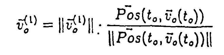
In der Fig. 4 ist mit 4 und 4' das abzuwehrende Ziel bezeichnet, das in einer Treff- bzw. Abschussposition (4) und in einer der Treff- bzw. Abschussposition vorhergehenden Position (4') dargestellt.In FIG. 4 , 4 and 4 ' denote the target to be defended, which is shown in a hit or shoot position ( 4 ) and in a position ( 4' ) preceding the hit or shoot position.
Die vorstehend beschriebene Vorrichtung arbeitet wie folgt:The device described above works as follows:
Die Vorhalt-Recheneinheit 9 errechnet aus einer vorgegebenen Zerlegungsdistanz Dz,
einer Vorhaltgeschwindigkeit VOv und den Zieldaten Z unter Berücksichtigung von meteorologischen
Daten bei Geschossen mit Primär-und Sekundärballistik eine Treffdistanz
RT, eine Zerlegungszeit Tz und eine Subprojektilflugzeit ts. Hierbei ist Tz die Flugzeit des
Geschosses bis zum Zerlegungspunkt Pz und ts die Flugzeit eines in der Geschossrichtung
fliegenden Subprojektiles vom Zerlegungspunkt Pz bis zum Treffpunkt Pf (Fig.3,4).The
Die Vorhaltgeschwindigkeit VOv wird beispielsweise aus dem Mittelwert einer Anzahl
über die Data-Transmission 17 zugeführter gemessener Geschossgeschwindigkeiten Vm
gebildet, die der aktuellen gemessenen Geschossgeschwindigkeit Vm unmittelbar vorhergehen. The lead speed VOv is formed, for example, from the mean value of a number of measured projectile speeds Vm supplied via the
Die Vorhalt-Recheneinheit 9 ermittelt ferner einen Geschützwinkel a des Azimutes und
einen Geschützwinkel λ der Elevation. Die Grössen α, λ, Tz und VOv werden der Korrektur-Recheneinheit
12 zugeführt, die wie nachstehend näher beschrieben einen Korrekturfaktor
K errechnet. Die Grössen α, λ, Tz, VOv und K werden als Schiesselemente
des Treffpunktes bezeichnet und über die Data-Transmission 17 dem Geschützrechner
zugeführt, wobei die Schiesselemente α und λ dem Geschützservo 15 und die Schiesselemente
VOv, Tz und K der Aufdatier-Recheneinheit 11 zugeführt werden. Wenn nur
Primärballistik zur Anwendung kommt, so wird anstelle der Zerlegungszeit Tz die Treffzeit
Tf = Tz+ts übermittelt (Fig.1, Fig.4).The
Die vorstehend beschriebenen Berechnungen werden taktweise wiederholt durchgeführt, so dass jeweils im aktuellen Takt i die neuesten Daten α, λ, Tz oderTf, VOv und K für eine bestimmte Gültigkeitsdauer zur Verfügung stehen.The calculations described above are repeated in cycles, so that in the current clock i the newest data α, λ, Tz orTf, VOv and K for a certain period of validity is available.
Zwischen den Taktwerten wird für die aktuellen (laufende) Zeit (t) jeweils interpoliert bzw. extrapoliert.Between the cycle values, the current (running) time (t) is interpolated or extrapolated.
Die Ballistik eines Geschosses wird durch ein System von Differentialgleichungen der
Form
![]()
![]()
![]()
![]()
![]()
![]()
![]()
![]()

![]()
![]()
![]()
![]()
![]()
![]()
![]()
![]()
![]()
![]()

![]()

![]()
![]()
![]()
![]()
![]()
![]()
![]()
![]()
![]()
![]()
![]()
![]()
![]()
![]()
![]()
![]()
![]()
![]()
![]()
Die vorstehend angewendete mathematische bzw. physikalische Notation bedeutet:
-
ν - ein Vektor
- ∥
ν ∥ - Norm des Vektors
- 〈
u ,ν 〉 - Skalarprodukt
- .
- skalare oder Matrixmultiplikation
- g := A
- die Grösse g wird definiert als Ausdruck A
- g = g(x 1,...,xn )
- die Grösse g hängt ab von x1,....,xn
- t ↦ g(t)
- Zuordnung (t wird die Auswertung von g an der Stelle t zugeordnet)
- g ˙
- Ableitung von g nach der Zeit
- Dig(x 1,...,xn )
- partielle Ableitung von g nach der i-ten Variablen
- ∂ / ∂t g(t,x 1,...,xn )
- partielle Ableitung von g nach der Zeit t
- inf tM
- Infimum der Menge M über alle t
-
p G,ν G,a G - Position,Geschwindigkeit,Beschleunigung des Geschosses
-
p Z,ν Z,a Z - Position,Geschwindigkeit,Beschleunigung des Zieles
-
p rel ,ν rel ,a rel - relative Position,Geschwindigkeit,Beschleunigung Geschoss-Ziel
-

- Position der Rohrmündung
-
ν o - Vorhalt-Anfangsgeschwindigkeit des Geschosses
- ν o
- Betrag der Komponente der Vorhalt-Anfangsgeschwindigkeit des Geschosses in Rohrrichtung
- ν m
- Betrag der Komponente der effektiven Anfangsgeschwindigkeit des Geschosses in Rohrrichtung
- TG.
- Vorhalt-Flugzeit des Geschosses
- t*
- Flugzeit des Geschosses
- to
- Zeitpunkt zu dem das Geschoss die Rohrmündung passiert.
-
ν - a vector
- ∥
ν ∥ - Norm of the vector
- 〈
u ,ν 〉 - Dot product
- .
- scalar or matrix multiplication
- g : = A
- size g is defined as expression A
- g = g ( x 1 , ..., x n )
- the size g depends on x 1 , ...., x n
- t ↦ g ( t )
- Assignment (t is assigned the evaluation of g at point t)
- g ˙
- Derivation of g after time
- D i g ( x 1 , ..., x n )
- partial derivative of g after the i-th variable
- ∂ / ∂ t g ( t , x 1 , ..., x n )
- partial derivative of g after time t
- inf t M
- Infimum of the set M over all t
-
p G ,ν G,a G - Position, speed, acceleration of the projectile
-
p Z ,ν Z ,a Z. - Position, speed, acceleration of the target
-
p rel ,ν rel ,a rel - relative position, speed, acceleration floor-target
-
- Position of the pipe mouth
-
ν O - Lead initial speed of the projectile
- ν o
- Amount of the component of the initial initial velocity of the projectile in the pipe direction
- ν m
- Amount of the component of the effective initial velocity of the projectile in the pipe direction
- TG .
- Lead flight time of the projectile
- t *
- Flight time of the projectile
- t o
- Time at which the bullet passes the muzzle.
Die Aufdatierungs-Recheneinheit 11 errechnet aus dem von der
Korrektur-Recheneinheit 12 zugeführten Korrekturfaktor K, der von
der Auswerteschaltung 10 zugeführten aktuellen gemessenen
Geschossgeschwindigkeit Vm und der von der Vorhalt-Recheneinheit 9 zugeführten
Vorhaltgeschwindigkeit Vov und Zerlegungszeit Tz eine korrigierte
Zerlegungszeit Tz (Vm) nach der Beziehung
Die korrigierte Zerlegungszeit Tz (Vm) wird je nach Zeitgültigkeit für die aktuelle
laufende Zeit t interpoliert bzw. extrapoliert. Die nun errechnete Zerlegungszeit
Tz (Vm,t) wird der Sendespule 27 des Programmierteils 23 der
Messvorrichtung 14 zugeführt und wie bereits vorstehend anhand der Fig.2
beschrieben induktiv auf ein vorbeifliegendes Geschoss 18 übertragen.The corrected decomposition time Tz (Vm) is interpolated or extrapolated depending on the validity for the current running time t. The disassembly time Tz (Vm, t) now calculated is supplied to the
Mit der Korrektur der Zerlegungszeit Tz kann die Zerlegungsdistanz Dz (Fig.3,4) unabhängig von den Streuungen der Geschossgeschwindigkeit, und/oder verursacht durch Verwendung nicht aktualisierter Werte gleichbleibend gehalten werden, so dass eine optimale Treff-bzw. Abschusswahrscheinlichkeit erzielt werden kann.With the correction of the disassembly time Tz, the disassembly distance Dz ( FIG. 3, 4 ) can be kept constant regardless of the variations in the projectile speed , and / or caused by the use of non-updated values, so that an optimal meeting or Probability of shooting can be achieved.
Claims (1)
- Method for determining a corrected fragmentation time (Tz(Vm)) for a programmably fragmentable projectile (12) fired from a gun-barrel (13) with a view to maintaining constant a given fragmentation distance (Dz) between a point of fragmentation (Pz) of the projectile (12) and a point of collision (Pf) of the projectile (12) with a target travelling at speed, in whichcharacterized in thatsensor data are measured from which a strike distance (RT) from the gun-barrel (13) to the target is computed,the velocity (Vm) of the fired projectile is measured at the muzzle of the gun-barrel (13), anddetermination of the corrected fragmentation time (Tz(Vm)) is based upon at leastthe said strike distance (RT),the said velocity (Vm) of the projectile (12), andthe fragmentation distance (Dz),where the correction factor (K), proceeding from the flight time (t*) of the shortest distance between a projectile and a target - given by the definitiona predicted velocity (VOv) of the projectile is also determined from the measured sensor data, andthe corrected fragmentation time (Tz(Vm)) is determined from the originally defined fragmentation time (Tz) by the relation
- Tz(Vm)
- stands for the corrected fragmentation time,
- Tz
- is the originally defined fragmentation time,
- K
- is a correction factor,
- Vm
- is the presently measured muzzle velocity of the projectile and
- VOv
- is a predicted velocity of the projectile,
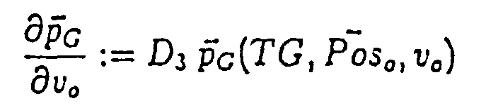
 and the partial derivative with respect to flight timeis found by the following calculation steps:
 simplifying Equation 6 by inserting the definitions

 differentiating Equation 6 with respect to the presently measured muzzle velocity, to give
 inserting a strike condition (Equation 3) included as a boundary condition in the system of differential equations of the ballistics, taking account of the definition for t*so that Equation 7 yields, for vm = vo
 simplifying Equation 7.1 by insertion of the definitionyielding the correction factor
-
p G,ν G,a G - stand for the position, velocity, acceleration of the projectile
-
p Z,ν Z,a Z - the position, velocity, acceleration of the target
-
p rel,ν rel,a rel - the relative position, velocity, acceleration of the projectile/target
-

- the position of the muzzle
-
ν o - predicted initial velocity of the projectile
- ν o
- the value of the predicted initial velocity component of the projectile in the direction of the barrel
- ν m
- the value of the actual initial velocity component of the projectile in the direction of the barrel
- TG
- the predicted flight time of the projectile
- t*
- the flight time of the projectile
- to
- the instant at which the projectile passes through the muzzle of the barrel.
Applications Claiming Priority (3)
| Application Number | Priority Date | Filing Date | Title |
|---|---|---|---|
| CH1001/96 | 1996-04-19 | ||
| CH100196 | 1996-04-19 | ||
| CH100196 | 1996-04-19 |
Publications (2)
| Publication Number | Publication Date |
|---|---|
| EP0802391A1 EP0802391A1 (en) | 1997-10-22 |
| EP0802391B1 true EP0802391B1 (en) | 2000-12-13 |
Family
ID=4200143
Family Applications (1)
| Application Number | Title | Priority Date | Filing Date |
|---|---|---|---|
| EP96118044A Expired - Lifetime EP0802391B1 (en) | 1996-04-19 | 1996-11-11 | Method of identifying a corrected disintegration time of a programmable and frangible projectile |
Country Status (12)
| Country | Link |
|---|---|
| US (1) | US5834675A (en) |
| EP (1) | EP0802391B1 (en) |
| JP (1) | JP3891619B2 (en) |
| KR (1) | KR100410718B1 (en) |
| AT (1) | ATE198103T1 (en) |
| AU (1) | AU716346B2 (en) |
| CA (1) | CA2190384C (en) |
| DE (1) | DE59606214D1 (en) |
| NO (1) | NO311954B1 (en) |
| SG (1) | SG83658A1 (en) |
| TR (1) | TR199600952A1 (en) |
| ZA (1) | ZA969536B (en) |
Families Citing this family (18)
| Publication number | Priority date | Publication date | Assignee | Title |
|---|---|---|---|---|
| FR2761767B1 (en) * | 1997-04-03 | 1999-05-14 | Giat Ind Sa | METHOD FOR PROGRAMMING IN FLIGHT A TRIGGERING MOMENT OF A PROJECTILE ELEMENT, FIRE CONTROL AND ROCKET IMPLEMENTING SUCH A METHOD |
| DK0992758T3 (en) | 1998-10-08 | 2007-06-18 | Contraves Ag | Method and apparatus for correcting the disintegration time or disintegration speed of a spin-stabilized projectile |
| EP0992762B1 (en) | 1998-10-08 | 2002-03-06 | Oerlikon Contraves Ag | Method and device for transmitting information to a programmable projectile |
| ATE227839T1 (en) * | 1998-10-08 | 2002-11-15 | Contraves Pyrotec Ag | METHOD FOR CORRECTING A PRE-PROGRAMMED TRIGGER OF A PROCESS IN A SPIN-STABILIZED MISSILE, DEVICE FOR IMPLEMENTING THE METHOD AND USE OF THE DEVICE |
| US20040237762A1 (en) * | 1999-11-03 | 2004-12-02 | Metal Storm Limited | Set defence means |
| US6497170B1 (en) * | 2001-07-05 | 2002-12-24 | The United States Of America As Represented By The Secretary Of The Army | Muzzle brake vibration absorber |
| ATE391893T1 (en) * | 2003-02-26 | 2008-04-15 | Rwm Schweiz Ag | METHOD FOR PROGRAMMING THE DISASSEMBLY OF PROJECTILES AND TUBE WEAPONS USING A PROGRAMMING SYSTEM |
| US7533612B1 (en) * | 2004-09-23 | 2009-05-19 | The United States Of America As Represented By The Secretary Of The Army | Projectile height of burst determination method and system |
| DE102009011447B9 (en) * | 2009-03-03 | 2012-08-16 | Diehl Bgt Defence Gmbh & Co. Kg | Method for igniting a warhead of a grenade and vehicle |
| US11047663B1 (en) * | 2010-11-10 | 2021-06-29 | True Velocity Ip Holdings, Llc | Method of coding polymer ammunition cartridges |
| DE102011018248B3 (en) | 2011-04-19 | 2012-03-29 | Rheinmetall Air Defence Ag | Device and method for programming a projectile |
| DE102011106198B3 (en) | 2011-06-07 | 2012-03-15 | Rheinmetall Air Defence Ag | Method for determining muzzle exit velocity of air burst munition, involves determining correction factor, and weighing correction factor, and correcting measured muzzle exit velocity of following blast using weighed correction factor |
| US10514234B2 (en) | 2013-03-27 | 2019-12-24 | Nostromo Holdings, Llc | Method and apparatus for improving the aim of a weapon station, firing a point-detonating or an air-burst projectile |
| US11933585B2 (en) | 2013-03-27 | 2024-03-19 | Nostromo Holdings, Llc | Method and apparatus for improving the aim of a weapon station, firing a point-detonating or an air-burst projectile |
| EP2894429B1 (en) * | 2014-01-08 | 2018-08-15 | Nostromo Holdings, LLC | Mortar safety device |
| US9740326B2 (en) * | 2015-03-31 | 2017-08-22 | Synaptics Incorporated | Sensor array with split-drive differential sensing |
| FR3071596B1 (en) * | 2017-09-27 | 2019-10-18 | Thales | METHOD AND DEVICE FOR LAUNCHING PROJECTILES ON A TARGET TO BE REACHED |
| US10883809B1 (en) * | 2019-05-07 | 2021-01-05 | U.S. Government As Represented By The Secretary Of The Army | Muzzle velocity correction |
Family Cites Families (17)
| Publication number | Priority date | Publication date | Assignee | Title |
|---|---|---|---|---|
| US4142442A (en) * | 1971-12-08 | 1979-03-06 | Avco Corporation | Digital fuze |
| US4267776A (en) * | 1979-06-29 | 1981-05-19 | Motorola, Inc. | Muzzle velocity compensating apparatus and method for a remote set fuze |
| US4449041A (en) * | 1980-10-03 | 1984-05-15 | Raytheon Company | Method of controlling antiaircraft fire |
| US4625646A (en) * | 1980-10-06 | 1986-12-02 | The Boeing Aerospace Company | Aerial missile having multiple submissiles with individual control of submissible ejection |
| FR2514884B1 (en) * | 1981-10-20 | 1985-07-12 | Sfim | METHOD AND DEVICE FOR GLOBALLY CORRECTING, FROM ONE SHOOTING TO THE NEXT, THE SHOOTING OF A TENSIONED WEAPON |
| DE3309147A1 (en) * | 1983-03-15 | 1984-09-20 | Rainer Dipl.-Phys. 6901 Gaiberg Berthold | Method and arrangement for correcting an ignition time |
| US4799429A (en) * | 1984-03-30 | 1989-01-24 | Isc Technologies, Inc. | Programming circuit for individual bomblets in a cluster bomb |
| US4750423A (en) * | 1986-01-31 | 1988-06-14 | Loral Corporation | Method and system for dispensing sub-units to achieve a selected target impact pattern |
| FR2609165A1 (en) * | 1986-12-31 | 1988-07-01 | Thomson Brandt Armements | PROJECTILE COMPRISING SUB-PROJECTILES WITH A PREFINED EFFICIENCY ZONE |
| US4837718A (en) * | 1987-02-05 | 1989-06-06 | Lear Siegler, Inc. | Doppler radar method and apparatus for measuring a projectile's muzzle velocity |
| DE3862536D1 (en) * | 1987-07-20 | 1991-05-29 | Oerlikon Buehrle Ag | DEVICE FOR DIGITALLY ADJUSTING A COUNTER TO RELEASE A TIMER ON A FLOOR. |
| GB2226624B (en) * | 1987-12-12 | 1991-07-03 | Thorn Emi Electronics Ltd | Projectile |
| DE3830518A1 (en) * | 1988-09-08 | 1990-03-22 | Rheinmetall Gmbh | DEVICE FOR SETTING A FLOOR TIME |
| DE59100529D1 (en) * | 1990-07-19 | 1993-12-02 | Contraves Ag | Receiving coil for a programmable projectile detonator. |
| EP0512856B1 (en) * | 1991-05-08 | 1998-11-04 | Electronic Data Systems Corporation | Weapon system |
| CA2082448C (en) * | 1991-05-08 | 2002-04-30 | Christopher Robert Gent | Weapons systems |
| US5497704A (en) * | 1993-12-30 | 1996-03-12 | Alliant Techsystems Inc. | Multifunctional magnetic fuze |
-
1996
- 1996-11-08 NO NO19964757A patent/NO311954B1/en not_active IP Right Cessation
- 1996-11-11 AT AT96118044T patent/ATE198103T1/en active
- 1996-11-11 EP EP96118044A patent/EP0802391B1/en not_active Expired - Lifetime
- 1996-11-11 DE DE59606214T patent/DE59606214D1/en not_active Expired - Lifetime
- 1996-11-13 AU AU71727/96A patent/AU716346B2/en not_active Ceased
- 1996-11-13 SG SG9611114A patent/SG83658A1/en unknown
- 1996-11-13 ZA ZA969536A patent/ZA969536B/en unknown
- 1996-11-14 US US08/749,329 patent/US5834675A/en not_active Expired - Lifetime
- 1996-11-14 CA CA002190384A patent/CA2190384C/en not_active Expired - Fee Related
- 1996-11-18 KR KR1019960054801A patent/KR100410718B1/en not_active IP Right Cessation
- 1996-11-25 JP JP31345596A patent/JP3891619B2/en not_active Expired - Fee Related
- 1996-11-27 TR TR96/00952A patent/TR199600952A1/en unknown
Also Published As
| Publication number | Publication date |
|---|---|
| KR970070943A (en) | 1997-11-07 |
| CA2190384C (en) | 2003-09-30 |
| DE59606214D1 (en) | 2001-01-18 |
| NO964757L (en) | 1997-10-20 |
| TR199600952A1 (en) | 1997-11-21 |
| ATE198103T1 (en) | 2000-12-15 |
| US5834675A (en) | 1998-11-10 |
| SG83658A1 (en) | 2001-10-16 |
| AU7172796A (en) | 1997-10-23 |
| CA2190384A1 (en) | 1997-10-20 |
| ZA969536B (en) | 1997-06-17 |
| AU716346B2 (en) | 2000-02-24 |
| JP3891619B2 (en) | 2007-03-14 |
| KR100410718B1 (en) | 2004-04-03 |
| NO311954B1 (en) | 2002-02-18 |
| NO964757D0 (en) | 1996-11-08 |
| EP0802391A1 (en) | 1997-10-22 |
| JPH09287899A (en) | 1997-11-04 |
Similar Documents
| Publication | Publication Date | Title |
|---|---|---|
| EP0802391B1 (en) | Method of identifying a corrected disintegration time of a programmable and frangible projectile | |
| EP0802392B1 (en) | Method and device for identifying a corrected desintegration time of a programmable and frangible projectile | |
| DE69708343T2 (en) | Passive speed data system | |
| EP0802390B1 (en) | Method for identifying a corrected desintegration time of a programmable and frangible projectile | |
| EP1726911A1 (en) | Method and device for time setting and for correcting the ignition time in a projectile | |
| EP0118122A1 (en) | Method and apparatus for setting the delay of a projectile time-fuse | |
| DE2605374B2 (en) | Device for digital setting of a counter for triggering a time fuse in a floor | |
| EP0769673B1 (en) | Method and device to program time fuses for projectiles | |
| DE2347374C2 (en) | Distance fuse for a warhead | |
| DE2423704A1 (en) | DELAY IGNITER FOR STORIES | |
| EP1482311B1 (en) | Device and method for the determination of the muzzle velocity of a projectile | |
| DE2452586C3 (en) | Method and device for determining the duration of the flight path of a projectile | |
| EP2699871B1 (en) | Device and method for programming a projectile | |
| DE1623362B2 (en) | Device for igniting an explosive charge or for triggering a function | |
| EP0992758B1 (en) | Method and device for correcting the disintegration time or the disintegration turn count of a spin-stabilized programmable projectile | |
| EP0992761B1 (en) | Method for correcting the preprogrammed triggering of a process in a spin-stabilized projectile, device for carrying out said method and use of this device | |
| EP0992762B1 (en) | Method and device for transmitting information to a programmable projectile | |
| DE102011106198B3 (en) | Method for determining muzzle exit velocity of air burst munition, involves determining correction factor, and weighing correction factor, and correcting measured muzzle exit velocity of following blast using weighed correction factor | |
| DE60219564T2 (en) | A method of adjusting a projectile fuse, programmer and timing fuse used in such a method | |
| CH656453A5 (en) | Device for firing simulation using light pulses | |
| DE3716450C1 (en) | Setting electronic timer for munition detonator - entering type, temp. of drive charge weather and target data in fuse ignition computer | |
| DE3925000C1 (en) | Flight time measuring method for shell | |
| EP2226607A2 (en) | Method for igniting a warhead of a grenade and vehicle | |
| EP1162428B1 (en) | Method and device for igniting a warhead in a target tracking missile | |
| DE3903802C2 (en) |
Legal Events
| Date | Code | Title | Description |
|---|---|---|---|
| PUAI | Public reference made under article 153(3) epc to a published international application that has entered the european phase |
Free format text: ORIGINAL CODE: 0009012 |
|
| AK | Designated contracting states |
Kind code of ref document: A1 Designated state(s): AT BE CH DE FR GB IT LI NL SE |
|
| 17P | Request for examination filed |
Effective date: 19971211 |
|
| 17Q | First examination report despatched |
Effective date: 19990526 |
|
| RTI1 | Title (correction) |
Free format text: METHOD OF IDENTIFYING A CORRECTED DISINTEGRATION TIME OF A PROGRAMMABLE AND FRANGIBLE PROJECTILE |
|
| RAP1 | Party data changed (applicant data changed or rights of an application transferred) |
Owner name: OERLIKON CONTRAVES AG |
|
| GRAG | Despatch of communication of intention to grant |
Free format text: ORIGINAL CODE: EPIDOS AGRA |
|
| GRAG | Despatch of communication of intention to grant |
Free format text: ORIGINAL CODE: EPIDOS AGRA |
|
| GRAH | Despatch of communication of intention to grant a patent |
Free format text: ORIGINAL CODE: EPIDOS IGRA |
|
| GRAH | Despatch of communication of intention to grant a patent |
Free format text: ORIGINAL CODE: EPIDOS IGRA |
|
| GRAA | (expected) grant |
Free format text: ORIGINAL CODE: 0009210 |
|
| AK | Designated contracting states |
Kind code of ref document: B1 Designated state(s): AT BE CH DE FR GB IT LI NL SE |
|
| REF | Corresponds to: |
Ref document number: 198103 Country of ref document: AT Date of ref document: 20001215 Kind code of ref document: T |
|
| REG | Reference to a national code |
Ref country code: CH Ref legal event code: EP |
|
| REG | Reference to a national code |
Ref country code: CH Ref legal event code: NV Representative=s name: OK PAT AG |
|
| REF | Corresponds to: |
Ref document number: 59606214 Country of ref document: DE Date of ref document: 20010118 |
|
| GBT | Gb: translation of ep patent filed (gb section 77(6)(a)/1977) |
Effective date: 20010112 |
|
| ET | Fr: translation filed | ||
| ITF | It: translation for a ep patent filed | ||
| PLBE | No opposition filed within time limit |
Free format text: ORIGINAL CODE: 0009261 |
|
| STAA | Information on the status of an ep patent application or granted ep patent |
Free format text: STATUS: NO OPPOSITION FILED WITHIN TIME LIMIT |
|
| 26N | No opposition filed | ||
| REG | Reference to a national code |
Ref country code: GB Ref legal event code: IF02 |
|
| PGFP | Annual fee paid to national office [announced via postgrant information from national office to epo] |
Ref country code: AT Payment date: 20101112 Year of fee payment: 15 |
|
| PGFP | Annual fee paid to national office [announced via postgrant information from national office to epo] |
Ref country code: GB Payment date: 20101118 Year of fee payment: 15 |
|
| REG | Reference to a national code |
Ref country code: DE Ref legal event code: R082 Ref document number: 59606214 Country of ref document: DE Representative=s name: THUL PATENTANWALTSGESELLSCHAFT MBH, DE |
|
| REG | Reference to a national code |
Ref country code: DE Ref legal event code: R084 Ref document number: 59606214 Country of ref document: DE Effective date: 20111019 |
|
| PGFP | Annual fee paid to national office [announced via postgrant information from national office to epo] |
Ref country code: BE Payment date: 20111110 Year of fee payment: 16 |
|
| REG | Reference to a national code |
Ref country code: DE Ref legal event code: R082 Ref document number: 59606214 Country of ref document: DE Representative=s name: THUL PATENTANWALTSGESELLSCHAFT MBH, DE |
|
| REG | Reference to a national code |
Ref country code: DE Ref legal event code: R082 Ref document number: 59606214 Country of ref document: DE Representative=s name: THUL PATENTANWALTSGESELLSCHAFT MBH, DE Effective date: 20111229 Ref country code: DE Ref legal event code: R082 Ref document number: 59606214 Country of ref document: DE Representative=s name: THUL PATENTANWALTSGESELLSCHAFT MBH, DE Effective date: 20120523 Ref country code: DE Ref legal event code: R081 Ref document number: 59606214 Country of ref document: DE Owner name: RHEINMETALL AIR DEFENCE AG, CH Free format text: FORMER OWNER: OERLIKON CONTRAVES AG, ZUERICH, CH Effective date: 20120523 Ref country code: DE Ref legal event code: R081 Ref document number: 59606214 Country of ref document: DE Owner name: RHEINMETALL AIR DEFENCE AG, CH Free format text: FORMER OWNER: OERLIKON-CONTRAVES AG, ZUERICH, CH Effective date: 20111229 |
|
| BERE | Be: lapsed |
Owner name: *OERLIKON CONTRAVES A.G. Effective date: 20121130 |
|
| REG | Reference to a national code |
Ref country code: AT Ref legal event code: MM01 Ref document number: 198103 Country of ref document: AT Kind code of ref document: T Effective date: 20121111 |
|
| GBPC | Gb: european patent ceased through non-payment of renewal fee |
Effective date: 20121111 |
|
| PG25 | Lapsed in a contracting state [announced via postgrant information from national office to epo] |
Ref country code: AT Free format text: LAPSE BECAUSE OF NON-PAYMENT OF DUE FEES Effective date: 20121111 |
|
| PG25 | Lapsed in a contracting state [announced via postgrant information from national office to epo] |
Ref country code: BE Free format text: LAPSE BECAUSE OF NON-PAYMENT OF DUE FEES Effective date: 20121130 |
|
| PG25 | Lapsed in a contracting state [announced via postgrant information from national office to epo] |
Ref country code: GB Free format text: LAPSE BECAUSE OF NON-PAYMENT OF DUE FEES Effective date: 20121111 |
|
| PGFP | Annual fee paid to national office [announced via postgrant information from national office to epo] |
Ref country code: DE Payment date: 20141119 Year of fee payment: 19 Ref country code: CH Payment date: 20141119 Year of fee payment: 19 Ref country code: FR Payment date: 20141119 Year of fee payment: 19 Ref country code: SE Payment date: 20141119 Year of fee payment: 19 |
|
| PGFP | Annual fee paid to national office [announced via postgrant information from national office to epo] |
Ref country code: NL Payment date: 20141119 Year of fee payment: 19 |
|
| PGFP | Annual fee paid to national office [announced via postgrant information from national office to epo] |
Ref country code: IT Payment date: 20141125 Year of fee payment: 19 |
|
| REG | Reference to a national code |
Ref country code: DE Ref legal event code: R119 Ref document number: 59606214 Country of ref document: DE |
|
| REG | Reference to a national code |
Ref country code: CH Ref legal event code: PL |
|
| PG25 | Lapsed in a contracting state [announced via postgrant information from national office to epo] |
Ref country code: CH Free format text: LAPSE BECAUSE OF NON-PAYMENT OF DUE FEES Effective date: 20151130 Ref country code: IT Free format text: LAPSE BECAUSE OF NON-PAYMENT OF DUE FEES Effective date: 20151111 Ref country code: LI Free format text: LAPSE BECAUSE OF NON-PAYMENT OF DUE FEES Effective date: 20151130 |
|
| REG | Reference to a national code |
Ref country code: NL Ref legal event code: MM Effective date: 20151201 |
|
| REG | Reference to a national code |
Ref country code: FR Ref legal event code: ST Effective date: 20160729 |
|
| PG25 | Lapsed in a contracting state [announced via postgrant information from national office to epo] |
Ref country code: SE Free format text: LAPSE BECAUSE OF NON-PAYMENT OF DUE FEES Effective date: 20151112 |
|
| PG25 | Lapsed in a contracting state [announced via postgrant information from national office to epo] |
Ref country code: NL Free format text: LAPSE BECAUSE OF NON-PAYMENT OF DUE FEES Effective date: 20151201 |
|
| PG25 | Lapsed in a contracting state [announced via postgrant information from national office to epo] |
Ref country code: DE Free format text: LAPSE BECAUSE OF NON-PAYMENT OF DUE FEES Effective date: 20160601 |
|
| PG25 | Lapsed in a contracting state [announced via postgrant information from national office to epo] |
Ref country code: FR Free format text: LAPSE BECAUSE OF NON-PAYMENT OF DUE FEES Effective date: 20151130 |