EP0802372B1 - Procédé et dispositif de commande d'un processus de combustion dans une chaudière - Google Patents
Procédé et dispositif de commande d'un processus de combustion dans une chaudière Download PDFInfo
- Publication number
- EP0802372B1 EP0802372B1 EP97710009A EP97710009A EP0802372B1 EP 0802372 B1 EP0802372 B1 EP 0802372B1 EP 97710009 A EP97710009 A EP 97710009A EP 97710009 A EP97710009 A EP 97710009A EP 0802372 B1 EP0802372 B1 EP 0802372B1
- Authority
- EP
- European Patent Office
- Prior art keywords
- flame
- fact
- local
- low
- sensor
- Prior art date
- Legal status (The legal status is an assumption and is not a legal conclusion. Google has not performed a legal analysis and makes no representation as to the accuracy of the status listed.)
- Expired - Lifetime
Links
- 238000000034 method Methods 0.000 title claims abstract description 22
- 238000002485 combustion reaction Methods 0.000 title claims description 19
- 239000000446 fuel Substances 0.000 claims abstract description 17
- 230000015572 biosynthetic process Effects 0.000 claims abstract description 5
- 239000003365 glass fiber Substances 0.000 claims description 6
- 238000011144 upstream manufacturing Methods 0.000 claims 4
- 238000010183 spectrum analysis Methods 0.000 claims 2
- 230000003595 spectral effect Effects 0.000 abstract description 12
- 230000001105 regulatory effect Effects 0.000 abstract description 3
- 239000003245 coal Substances 0.000 description 3
- 230000001276 controlling effect Effects 0.000 description 3
- 238000000354 decomposition reaction Methods 0.000 description 3
- 239000000835 fiber Substances 0.000 description 3
- 239000000567 combustion gas Substances 0.000 description 2
- 230000001419 dependent effect Effects 0.000 description 2
- 238000011156 evaluation Methods 0.000 description 2
- 238000012549 training Methods 0.000 description 2
- 229930091051 Arenine Natural products 0.000 description 1
- 238000011109 contamination Methods 0.000 description 1
- 238000011161 development Methods 0.000 description 1
- 230000018109 developmental process Effects 0.000 description 1
- 238000010586 diagram Methods 0.000 description 1
- 230000002349 favourable effect Effects 0.000 description 1
- 230000004807 localization Effects 0.000 description 1
- 238000005259 measurement Methods 0.000 description 1
- 239000000203 mixture Substances 0.000 description 1
- 150000003839 salts Chemical class 0.000 description 1
- 238000001228 spectrum Methods 0.000 description 1
- 230000002123 temporal effect Effects 0.000 description 1
Images
Classifications
-
- F—MECHANICAL ENGINEERING; LIGHTING; HEATING; WEAPONS; BLASTING
- F23—COMBUSTION APPARATUS; COMBUSTION PROCESSES
- F23N—REGULATING OR CONTROLLING COMBUSTION
- F23N5/00—Systems for controlling combustion
- F23N5/02—Systems for controlling combustion using devices responsive to thermal changes or to thermal expansion of a medium
- F23N5/08—Systems for controlling combustion using devices responsive to thermal changes or to thermal expansion of a medium using light-sensitive elements
- F23N5/082—Systems for controlling combustion using devices responsive to thermal changes or to thermal expansion of a medium using light-sensitive elements using electronic means
-
- F—MECHANICAL ENGINEERING; LIGHTING; HEATING; WEAPONS; BLASTING
- F23—COMBUSTION APPARATUS; COMBUSTION PROCESSES
- F23N—REGULATING OR CONTROLLING COMBUSTION
- F23N2229/00—Flame sensors
- F23N2229/14—Flame sensors using two or more different types of flame sensor
-
- F—MECHANICAL ENGINEERING; LIGHTING; HEATING; WEAPONS; BLASTING
- F23—COMBUSTION APPARATUS; COMBUSTION PROCESSES
- F23N—REGULATING OR CONTROLLING COMBUSTION
- F23N2229/00—Flame sensors
- F23N2229/16—Flame sensors using two or more of the same types of flame sensor
-
- F—MECHANICAL ENGINEERING; LIGHTING; HEATING; WEAPONS; BLASTING
- F23—COMBUSTION APPARATUS; COMBUSTION PROCESSES
- F23N—REGULATING OR CONTROLLING COMBUSTION
- F23N2229/00—Flame sensors
- F23N2229/20—Camera viewing
Definitions
- the invention relates to a method and a device for controlling a Combustion process in a boiler according to the preamble of claim 1 or Claim 10.
- Burners collect data on various process parameters and use them to derive Interventions on manipulated variables processed. For example, temperature and Composition of combustion gases at the boiler outlet, steam parameters such as Temperature and steam mass flow and temperatures measured in the boiler.
- interventions on the actuators of the Combustion process derived so that, for example, at a high NOX concentration in the combustion gas actuators of the burner to be operated globally supply higher amounts of combustion air.
- a Measurement of a relatively low steam mass flow through the fuel supply appropriate control of actuators can be increased. Stable control of the The combustion process with the known methods is due to several at the same time Parameters to be observed are relatively difficult.
- EP-A-0 616 200 describes a device for control and evaluation a combustion process in which a CCD camera has a high spatial resolution captured the fields of a flame.
- a CCD camera has a high spatial resolution captured the fields of a flame.
- nine pixels of the CCD camera filtered such that they are adjacent spectral bands of the detect visible light, the resulting curve of each nine Pixel is added to a total.
- the spectral resolution is roughly tripled, nevertheless is a high spatial resolution and low spectral resolution, since all radiators (radical radiators) falling in one area are added together and taking into account the temperature dependent basis as well also a precise determination of the exact wavelength of one or more Do not allow peaks in the spectrum. Due to peaks due to contamination the fuel, e.g. by salts, the evaluation is falsified and the Regulation misguided accordingly.
- EP-A-0 581 451 describes a method for controlling a combustion process, in which the time course of the various fields of the Process are recorded.
- the flame formation behavior in the actual Combustion process of the fuel in a burner number can provide data on a direct control can be provided.
- others will Process parameters are already automatically regulated. Will the flame come with an optimal training, it can be assumed that the usual process parameters are at least in the vicinity of an optimal operating point.
- the supply of primary-secondary and / or Tertiary air the supply of fuel and fluidic Adjustment devices of the burner can be set.
- the swirl at Entry of the fuel can be set.
- the fuel / air ratio can be local can be optimally adjusted. This enables either the amount of fuel or set to an optimal value in air to achieve the desired value Achieve fuel / air ratio.
- the high location and low spectral resolution sensor is preferred as a CCD camera educated. With the CCD camera, the shape and the environment of the Flame can be detected. This sensor preferably detects the flow field of the flame. It can also detect a relatively accurate local distribution of the temperature.
- the sensor with low local and high spectral resolution is preferred as a glass fiber cable assigned spectral decomposition devices.
- a spectral decomposition device can easily be designed as a grid, slit or prism his. This is preferred with the low-location and high-spectral resolution sensor Radical and / or temperature field of the flame detected. Here is the registration of individual Radicals of special and their exact localization rather less Importance.,
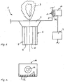
- Fig. Shows schematically a section of a boiler for coal combustion.
- FIG. 2 shows a view of the detector from FIG. 1.
- the boiler 1 for coal combustion shown schematically in FIG. 1 has a burner 2 on. Via the burner 2, fuel and air are introduced into the boiler 1 and under Formation of a flame 3 burned.
- the essentially cylindrical burner 2 comprises an outer air duct 4, an inner air duct 5 and an entry duct 6 for fuel entry. On that An inlet funnel 7 is provided for the boiler 1 facing the end of the burner 2.
- a wall 8 of the boiler 1 is connected to a computing device 9 Detector 10 added.
- the detector 10 is directed towards the flame 3 and comprises a sensor which is designed as a CCD camera 11 and has a high local and low spectral resolution and one through fiber optic cable 12 with associated spectral decomposition devices trained low-location and high-spectral resolution sensor.
- the fiber optic cables 12 of the sensor below the lens of the CCD camera 11 arranged.
- the computing device 9 is connected to actuators via signal lines (not shown) of the burner 2 and a fuel mill, not shown.
- the fiber optic cables 12 are arranged like a fan.
- the shape and the flow field are determined by the sensor 11 and detects the radical and temperature field of the flame 3 via the sensor 12.
- the output signals of the detector 10 are forwarded to the computing device 9 and there to control signals for the actuators of the burner 2 and the fuel mill Control of flame 3 processed.
Landscapes
- Engineering & Computer Science (AREA)
- Chemical & Material Sciences (AREA)
- Combustion & Propulsion (AREA)
- Mechanical Engineering (AREA)
- General Engineering & Computer Science (AREA)
- Control Of Combustion (AREA)
- Incineration Of Waste (AREA)
- Regulation And Control Of Combustion (AREA)
- Control Of Steam Boilers And Waste-Gas Boilers (AREA)
Claims (14)
- Procédé de commande d'un processus de combustion dans une chaudière (1) avec un brûleur (2), par l'intermédiaire duquel un combustible est introduit dans la chaudière (1) et brûlé en formant une flamme (3), dans lequel un champ de température, un champ d'écoulement et un champ de radicaux de la flamme (3) sont relevés par un détecteur (10) et la flamme (3) est régulée en fonction des signaux de sortie du détecteur (10) traités dans un dispositif de calcul (9) par des interventions sur des grandeurs de réglage sur le brûleur (2) et/ou sur un dispositif placé avant le brûleur (2), le détecteur (10) relevant les champs de la flamme (3) au moyen d'un capteur (11) à haute résolution spatiale et faible résolution spectrale, caractérisé en ce que le détecteur (10) relève divers points de la flamme (3) au moyen d'un autre capteur (12) à faible résolution spatiale et haute résolution spectrale.
- Procédé selon la revendication 1, caractérisé en ce que les variations temporelles du champ de température, du champ d'écoulement et/ou du champ de radicaux de la flamme (3) sont relevées.
- Procédé selon la revendication 1 ou 2, caractérisé en ce que le champ de température et le champ d'écoulement de la flamme (3) sont relevés par le capteur (11) à haute résolution spatiale et faible résolution spectrale.
- Procédé selon l'une des revendications 1 à 3, caractérisé en ce que le champ de radicaux de la flamme (3) est relevé par le capteur (12) à faible résolution spatiale et haute résolution spectrale.
- Procédé selon l'une des revendications 1 à 4, caractérisé en ce que le capteur à faible résolution spatiale et haute résolution spectrale comprend au moins un câble de fibres de verre (12) dirigé vers la flamme avec des dispositifs associés de décomposition spectrale.
- Procédé selon la revendication 5, caractérisé en ce que le capteur à faible résolution spatiale et haute résolution spectrale comprend plusieurs câbles de fibres de verre (12) disposés en éventail.
- Procédé selon l'une des revendications 1 à 6, caractérisé en ce que le capteur à haute résolution spatiale et faible résolution spectrale est conformé en appareil de photographie CCD (11).
- Procédé selon l'une des revendications 1 à 7, caractérisé en ce que les interventions sur des grandeurs de réglage sont effectuées sur un pulvérisateur de combustible placé avant le brûleur (2).
- Procédé selon l'une des revendications 1 à 8, caractérisé en ce que les interventions sur des grandeurs de réglage sont effectuées sur une alimentation en air de combustion placée avant le brûleur (2).
- Dispositif pour commander un processus de combustion dans une chaudière (1) avec un brûleur (2), par l'intermédiaire duquel un combustible est introduit dans la chaudière (1) et brûlé en formant une flamme (3), un champ de température, un champ d'écoulement et un champ de radicaux de la flamme pouvant être relevés par un détecteur (10) placé sur une paroi (8) de la chaudière (2) et dirigé vers la flamme (3) et relié à un dispositif de calcul (9) ; le brûleur (2) et/ou un dispositif placé avant le brûleur (2) pouvant être régulé au moyen de signaux de sortie du détecteur (10) traités dans un dispositif de calcul (9) par des interventions sur des grandeurs de réglage, le détecteur (10) relevant la configuration de la flamme (3) au moyen d'un capteur (11) à haute résolution spatiale et faible résolution spectrale, caractérisé en ce que le détecteur (10) relève divers points de la flamme (3) au moyen d'un autre capteur (12) à faible résolution spatiale et haute résolution spectrale.
- Dispositif selon la revendication 10, caractérisé en ce que le capteur à faible résolution spatiale et haute résolution spectrale comprend au moins un câble de fibres de verre (12) dirigé vers la flamme avec des dispositifs associés de décomposition spectrale.
- Dispositif selon la revendication 10 ou 11, caractérisé en ce que le capteur à haute résolution spatiale et faible résolution spectrale est conformé en appareil de photographie CCD (11).
- Dispositif selon la revendication 11 et 12, caractérisé en ce que les câbles de fibres de verre (12) sont placés sous l'objectif de l'appareil de photographie CCD (11).
- Dispositif selon la revendication 11 ou 13, caractérisé en ce que le capteur à faible résolution spatiale et haute résolution spectrale comprend plusieurs câbles de fibres de verre (12) disposés en éventail.
Applications Claiming Priority (2)
| Application Number | Priority Date | Filing Date | Title |
|---|---|---|---|
| DE19615141 | 1996-04-17 | ||
| DE19615141A DE19615141A1 (de) | 1996-04-17 | 1996-04-17 | Verfahren und Einrichtung zur Steuerung eines Verbrennungsprozesses in einem Kessel |
Publications (2)
| Publication Number | Publication Date |
|---|---|
| EP0802372A1 EP0802372A1 (fr) | 1997-10-22 |
| EP0802372B1 true EP0802372B1 (fr) | 2001-06-13 |
Family
ID=7791520
Family Applications (1)
| Application Number | Title | Priority Date | Filing Date |
|---|---|---|---|
| EP97710009A Expired - Lifetime EP0802372B1 (fr) | 1996-04-17 | 1997-04-15 | Procédé et dispositif de commande d'un processus de combustion dans une chaudière |
Country Status (7)
| Country | Link |
|---|---|
| EP (1) | EP0802372B1 (fr) |
| CN (1) | CN1177076A (fr) |
| AT (1) | ATE202196T1 (fr) |
| AU (1) | AU686966B2 (fr) |
| DE (2) | DE19615141A1 (fr) |
| ES (1) | ES2159825T3 (fr) |
| ZA (1) | ZA973113B (fr) |
Cited By (1)
| Publication number | Priority date | Publication date | Assignee | Title |
|---|---|---|---|---|
| CN102564768A (zh) * | 2011-11-14 | 2012-07-11 | 北京理工大学 | 一种基于光谱仪组件的非接触式发动机羽焰监测装置 |
Families Citing this family (13)
| Publication number | Priority date | Publication date | Assignee | Title |
|---|---|---|---|---|
| DE19649264A1 (de) * | 1996-11-28 | 1998-06-10 | Bfi Automation Gmbh | Flammenbeobachtungsgerät |
| DE19715040A1 (de) * | 1997-04-11 | 1998-10-15 | Bfi Automation Gmbh | Brenner und Betriebsverfahren für diesen |
| GB2344883B (en) * | 1998-12-16 | 2003-10-29 | Graviner Ltd Kidde | Flame monitoring methods and apparatus |
| DE19915663C1 (de) * | 1999-04-07 | 2000-12-28 | Siemens Ag | Verfahren zur Ermittlung des Strömungsfelds in einem Verbrennungsraum |
| DE19931111A1 (de) * | 1999-07-06 | 2001-01-11 | Electrowatt Tech Innovat Corp | Vorrichtung zum Überwachen von Flammen mit einem Flammenfühler bzw. Flammendetektor (Flammenwächter) und Verwendung desselben |
| DE10110181A1 (de) * | 2001-03-02 | 2002-09-12 | Powitec Intelligent Tech Gmbh | Meßvorrichtung, insbesondere zur Flammenbeobachtung während eines Verbrennungsprozesses |
| WO2002070953A1 (fr) * | 2001-03-02 | 2002-09-12 | Powitec Intelligent Technologies Gmbh | Dispositif de mesure, notamment destine a l'observation des flammes pendant un procede de combustion |
| EP2064491B1 (fr) | 2006-09-19 | 2010-02-17 | ABB Research LTD | Détecteur de flammes destiné à surveiller une flamme pendant un processus de combustion |
| EP2513618B1 (fr) * | 2009-12-16 | 2017-02-08 | ABB Research Ltd. | Détecteur optique de flamme |
| BRPI1003906A2 (pt) * | 2010-01-21 | 2013-02-26 | Universidade Federal Da Bahia | sistema de combustço de gÁs natural para o controle das correlaÇÕes entre radiaÇço tÉrmica formaÇço da fuligem e nox com a utilizaÇço da combustço enriquecida com oxigÊnio |
| FR2959298B1 (fr) * | 2010-04-23 | 2012-09-21 | Air Liquide | Four a flamme et procede de regulation de la combustion dans un four a flamme |
| DE102010044430A1 (de) | 2010-09-04 | 2012-03-08 | G I W E P Gesellschaft für industrielle Wärme, Energie- und Prozeßtechnik m.b.H | Verfahren zur Überwachung von gasbeheizten Ofenanlagen |
| RU207903U1 (ru) * | 2021-07-01 | 2021-11-23 | Павел Дмитриевич Дуньшин | Цифровое устройство для контроля, анализа и оптимизации процесса сжигания топлива в котлоагрегате |
Family Cites Families (12)
| Publication number | Priority date | Publication date | Assignee | Title |
|---|---|---|---|---|
| DE8017259U1 (de) * | 1980-06-28 | 1983-04-28 | Steag Ag, 4300 Essen | Feuerungsanlage zur gesteuerten verbrennung von festen fossilen brennstoffen |
| US4620491A (en) * | 1984-04-27 | 1986-11-04 | Hitachi, Ltd. | Method and apparatus for supervising combustion state |
| DE3508253A1 (de) * | 1985-03-08 | 1986-09-18 | Kurt-Henry Dipl.-Ing. 4030 Ratingen Mindermann | Verfahren zur flammenueberwachung und flammenwaechter fuer seine durchfuehrung |
| US4701624A (en) * | 1985-10-31 | 1987-10-20 | Santa Barbara Research Center | Fire sensor system utilizing optical fibers for remote sensing |
| DD286944A7 (de) * | 1988-05-30 | 1991-02-14 | Chemieanlagenbau Gmbh,De | Verfahren zur ueberwachung des prozesszustandes von getauchten gasfackeln zum zweck der regelung |
| DE3825931A1 (de) * | 1988-07-29 | 1990-02-01 | Martin Umwelt & Energietech | Verfahren und vorrichtung zur regelung der feuerungsleistung von verbrennungsanlagen |
| US4983853A (en) * | 1989-05-05 | 1991-01-08 | Saskatchewan Power Corporation | Method and apparatus for detecting flame |
| DE9011973U1 (de) * | 1989-09-28 | 1990-11-08 | Mindermann, Kurt-Henry, Dipl.-Ing., 4030 Ratingen | Einrichtung zur Überwachung und Bewertung von Flammen |
| DE69305706T2 (de) * | 1992-07-01 | 1997-03-20 | Toyota Motor Co Ltd | Verfahren zur Verbrennungsregelung |
| DE4305645C2 (de) * | 1993-02-24 | 1996-10-02 | Rwe Entsorgung Ag | Verfahren zur Ermittlung charakteristischer Eigenschaften von Radikale bildenden Prozessen, Verwendung des Verfahrens und Vorrichtung zur Durchführung des Verfahrens |
| JPH06273322A (ja) * | 1993-03-17 | 1994-09-30 | Hitachi Ltd | カメラ、分光システムおよびこれらを用いた燃焼評価装置 |
| DE4416270A1 (de) * | 1994-05-07 | 1995-11-09 | Peter L Prof Dr Andresen | Optimierung von turbulenten Verbrennungs- und Mischprozessen durch gezielte Zugabe von Substanzen |
-
1996
- 1996-04-17 DE DE19615141A patent/DE19615141A1/de not_active Withdrawn
-
1997
- 1997-04-11 ZA ZA973113A patent/ZA973113B/xx unknown
- 1997-04-15 EP EP97710009A patent/EP0802372B1/fr not_active Expired - Lifetime
- 1997-04-15 DE DE59703750T patent/DE59703750D1/de not_active Expired - Lifetime
- 1997-04-15 ES ES97710009T patent/ES2159825T3/es not_active Expired - Lifetime
- 1997-04-15 AT AT97710009T patent/ATE202196T1/de not_active IP Right Cessation
- 1997-04-17 AU AU18950/97A patent/AU686966B2/en not_active Ceased
- 1997-04-17 CN CN97110123A patent/CN1177076A/zh active Pending
Cited By (2)
| Publication number | Priority date | Publication date | Assignee | Title |
|---|---|---|---|---|
| CN102564768A (zh) * | 2011-11-14 | 2012-07-11 | 北京理工大学 | 一种基于光谱仪组件的非接触式发动机羽焰监测装置 |
| CN102564768B (zh) * | 2011-11-14 | 2014-02-12 | 北京理工大学 | 一种基于光谱仪组件的非接触式发动机羽焰监测装置 |
Also Published As
| Publication number | Publication date |
|---|---|
| ES2159825T3 (es) | 2001-10-16 |
| ZA973113B (en) | 1998-08-05 |
| CN1177076A (zh) | 1998-03-25 |
| EP0802372A1 (fr) | 1997-10-22 |
| DE19615141A1 (de) | 1997-10-23 |
| AU686966B2 (en) | 1998-02-12 |
| ATE202196T1 (de) | 2001-06-15 |
| AU1895097A (en) | 1997-11-13 |
| DE59703750D1 (de) | 2001-07-19 |
Similar Documents
| Publication | Publication Date | Title |
|---|---|---|
| EP0802372B1 (fr) | Procédé et dispositif de commande d'un processus de combustion dans une chaudière | |
| DE3825931C2 (fr) | ||
| DE69413277T2 (de) | Verbrennungsauswertungsvorrichtung zum Auswerten eines Verbrennungszustandes von Flammen | |
| EP2132543B1 (fr) | Procédé de détection, assisté par caméra, de l'intensité de rayonnement d'un produit de réaction chimique gazeux, applications du procédé et dispositif correspondant | |
| EP0612961B1 (fr) | Procédé de détermination de propriétés caractéristiques de processus formant des radicaux | |
| DE69216612T2 (de) | Einrichtung zur regelung der verbrennung, der umweltverschmutzung und chemischer prozesse | |
| EP3663648B1 (fr) | Dispositif de régulation du rapport de mélange de l'air de combustion et de gaz de combustion dans un processus de combustion | |
| WO1998040673A1 (fr) | Procede et dispositif pour l'analyse de la combustion et la surveillance d'une flamme dans une chambre de combustion | |
| DE3904272C3 (de) | Verfahren zum Erfassen der von mindestens zwei räumlich getrennten Stellen mindestens einer Verbrennungszone auf einem Rost ausgehenden Strahlung und Vorrichtung zum Erfassen einer solchen Strahlung | |
| DE4190919C2 (de) | Vorrichtung zur Ermittlung mitgerissener Teilchen im Inneren eines Ofens | |
| DE19847832C1 (de) | Verfahren zum Überwachen eines optischen Systems mit einer unmittelbar an einem Verbrennungsraum angeordneten Frontlinse und Überwachungsmodul | |
| EP0696708A1 (fr) | Méthode de régulation de la combustion pour installations de combustion, notammement d'installations d'incinérations de déchets | |
| DE2351922A1 (de) | Vorrichtung zum nachweis von makroteilchen in einem gasstrom | |
| EP1364164B1 (fr) | Dispositif de mesure, notamment destine a l'observation des flammes pendant un procede de combustion | |
| EP1048900A1 (fr) | Procédé et dispositif de contrôle de la combustion d' un combustible avec un pouvoir calorifique variable | |
| DE3823494C2 (de) | Verfahren und Vorrichtung zur Feuerungsdiagnose und dessen Ergebnisse verwendende Feuerungsregelung | |
| DE1526221A1 (de) | Verfahren und Vorrichtung zum Betrieb eines Vielfachoelbrenners | |
| EP1529182A1 (fr) | Procede pour controler un processus thermodynamique | |
| EP3872462A1 (fr) | Cellule chauffante pourvue d'unité de capteur optique | |
| WO2017121449A1 (fr) | Procédé d'évaluation et de régulation pour un brûleur mutlicombustible et dispositif d'évaluation et de régulation associé | |
| EP1051585B1 (fr) | Procede et dispositif pour faire fonctionner une installation de combustion | |
| DE19605287C2 (de) | Verfahren und Einrichtung zur Steuerung der Reisezeit eines Kessels | |
| EP2784392B1 (fr) | Détecteur de flamme | |
| DE102005036146A1 (de) | Anordnung zur optischen Flammenprüfung | |
| DE10347340A1 (de) | Vorrichtung und Verfahren zur Optimierung des Abgasausbrandes in Verbrennungsanlagen |
Legal Events
| Date | Code | Title | Description |
|---|---|---|---|
| PUAI | Public reference made under article 153(3) epc to a published international application that has entered the european phase |
Free format text: ORIGINAL CODE: 0009012 |
|
| 17P | Request for examination filed |
Effective date: 19970602 |
|
| AK | Designated contracting states |
Kind code of ref document: A1 Designated state(s): AT DE DK ES FR GB GR IE IT NL SE |
|
| 17Q | First examination report despatched |
Effective date: 19990119 |
|
| RAP1 | Party data changed (applicant data changed or rights of an application transferred) |
Owner name: ORFEUS COMBUSTION ENGINEERING GMBH |
|
| GRAG | Despatch of communication of intention to grant |
Free format text: ORIGINAL CODE: EPIDOS AGRA |
|
| GRAG | Despatch of communication of intention to grant |
Free format text: ORIGINAL CODE: EPIDOS AGRA |
|
| GRAH | Despatch of communication of intention to grant a patent |
Free format text: ORIGINAL CODE: EPIDOS IGRA |
|
| GRAH | Despatch of communication of intention to grant a patent |
Free format text: ORIGINAL CODE: EPIDOS IGRA |
|
| GRAA | (expected) grant |
Free format text: ORIGINAL CODE: 0009210 |
|
| AK | Designated contracting states |
Kind code of ref document: B1 Designated state(s): AT DE DK ES FR GB GR IE IT NL SE |
|
| PG25 | Lapsed in a contracting state [announced via postgrant information from national office to epo] |
Ref country code: NL Free format text: LAPSE BECAUSE OF FAILURE TO SUBMIT A TRANSLATION OF THE DESCRIPTION OR TO PAY THE FEE WITHIN THE PRESCRIBED TIME-LIMIT Effective date: 20010613 Ref country code: IE Free format text: LAPSE BECAUSE OF FAILURE TO SUBMIT A TRANSLATION OF THE DESCRIPTION OR TO PAY THE FEE WITHIN THE PRESCRIBED TIME-LIMIT Effective date: 20010613 |
|
| REF | Corresponds to: |
Ref document number: 202196 Country of ref document: AT Date of ref document: 20010615 Kind code of ref document: T |
|
| REF | Corresponds to: |
Ref document number: 59703750 Country of ref document: DE Date of ref document: 20010719 |
|
| REG | Reference to a national code |
Ref country code: IE Ref legal event code: FG4D Free format text: GERMAN |
|
| ITF | It: translation for a ep patent filed | ||
| PG25 | Lapsed in a contracting state [announced via postgrant information from national office to epo] |
Ref country code: SE Free format text: LAPSE BECAUSE OF FAILURE TO SUBMIT A TRANSLATION OF THE DESCRIPTION OR TO PAY THE FEE WITHIN THE PRESCRIBED TIME-LIMIT Effective date: 20010913 Ref country code: DK Free format text: LAPSE BECAUSE OF FAILURE TO SUBMIT A TRANSLATION OF THE DESCRIPTION OR TO PAY THE FEE WITHIN THE PRESCRIBED TIME-LIMIT Effective date: 20010913 |
|
| PG25 | Lapsed in a contracting state [announced via postgrant information from national office to epo] |
Ref country code: GR Free format text: LAPSE BECAUSE OF FAILURE TO SUBMIT A TRANSLATION OF THE DESCRIPTION OR TO PAY THE FEE WITHIN THE PRESCRIBED TIME-LIMIT Effective date: 20010914 |
|
| REG | Reference to a national code |
Ref country code: ES Ref legal event code: FG2A Ref document number: 2159825 Country of ref document: ES Kind code of ref document: T3 |
|
| GBT | Gb: translation of ep patent filed (gb section 77(6)(a)/1977) |
Effective date: 20010921 |
|
| NLV1 | Nl: lapsed or annulled due to failure to fulfill the requirements of art. 29p and 29m of the patents act | ||
| ET | Fr: translation filed | ||
| REG | Reference to a national code |
Ref country code: GB Ref legal event code: IF02 |
|
| PLBE | No opposition filed within time limit |
Free format text: ORIGINAL CODE: 0009261 |
|
| STAA | Information on the status of an ep patent application or granted ep patent |
Free format text: STATUS: NO OPPOSITION FILED WITHIN TIME LIMIT |
|
| 26N | No opposition filed | ||
| PGFP | Annual fee paid to national office [announced via postgrant information from national office to epo] |
Ref country code: AT Payment date: 20050414 Year of fee payment: 9 |
|
| PG25 | Lapsed in a contracting state [announced via postgrant information from national office to epo] |
Ref country code: AT Free format text: LAPSE BECAUSE OF NON-PAYMENT OF DUE FEES Effective date: 20060415 |
|
| PGFP | Annual fee paid to national office [announced via postgrant information from national office to epo] |
Ref country code: ES Payment date: 20080429 Year of fee payment: 12 |
|
| PGFP | Annual fee paid to national office [announced via postgrant information from national office to epo] |
Ref country code: GB Payment date: 20080421 Year of fee payment: 12 |
|
| GBPC | Gb: european patent ceased through non-payment of renewal fee |
Effective date: 20090415 |
|
| PG25 | Lapsed in a contracting state [announced via postgrant information from national office to epo] |
Ref country code: GB Free format text: LAPSE BECAUSE OF NON-PAYMENT OF DUE FEES Effective date: 20090415 |
|
| REG | Reference to a national code |
Ref country code: ES Ref legal event code: FD2A Effective date: 20090416 |
|
| PG25 | Lapsed in a contracting state [announced via postgrant information from national office to epo] |
Ref country code: ES Free format text: LAPSE BECAUSE OF NON-PAYMENT OF DUE FEES Effective date: 20090416 |
|
| PGFP | Annual fee paid to national office [announced via postgrant information from national office to epo] |
Ref country code: FR Payment date: 20110510 Year of fee payment: 15 Ref country code: DE Payment date: 20110421 Year of fee payment: 15 |
|
| PGFP | Annual fee paid to national office [announced via postgrant information from national office to epo] |
Ref country code: IT Payment date: 20110422 Year of fee payment: 15 |
|
| REG | Reference to a national code |
Ref country code: FR Ref legal event code: ST Effective date: 20121228 |
|
| REG | Reference to a national code |
Ref country code: DE Ref legal event code: R119 Ref document number: 59703750 Country of ref document: DE Effective date: 20121101 |
|
| PG25 | Lapsed in a contracting state [announced via postgrant information from national office to epo] |
Ref country code: FR Free format text: LAPSE BECAUSE OF NON-PAYMENT OF DUE FEES Effective date: 20120430 Ref country code: IT Free format text: LAPSE BECAUSE OF NON-PAYMENT OF DUE FEES Effective date: 20120415 |
|
| PG25 | Lapsed in a contracting state [announced via postgrant information from national office to epo] |
Ref country code: DE Free format text: LAPSE BECAUSE OF NON-PAYMENT OF DUE FEES Effective date: 20121101 |