EP0802129A2 - Conveyer path for articles, especially for luggage containers - Google Patents
Conveyer path for articles, especially for luggage containers Download PDFInfo
- Publication number
- EP0802129A2 EP0802129A2 EP97250117A EP97250117A EP0802129A2 EP 0802129 A2 EP0802129 A2 EP 0802129A2 EP 97250117 A EP97250117 A EP 97250117A EP 97250117 A EP97250117 A EP 97250117A EP 0802129 A2 EP0802129 A2 EP 0802129A2
- Authority
- EP
- European Patent Office
- Prior art keywords
- conveyor
- belt
- conveyor belt
- rollers
- toothed
- Prior art date
- Legal status (The legal status is an assumption and is not a legal conclusion. Google has not performed a legal analysis and makes no representation as to the accuracy of the status listed.)
- Granted
Links
Images
Classifications
-
- B—PERFORMING OPERATIONS; TRANSPORTING
- B65—CONVEYING; PACKING; STORING; HANDLING THIN OR FILAMENTARY MATERIAL
- B65G—TRANSPORT OR STORAGE DEVICES, e.g. CONVEYORS FOR LOADING OR TIPPING, SHOP CONVEYOR SYSTEMS OR PNEUMATIC TUBE CONVEYORS
- B65G19/00—Conveyors comprising an impeller or a series of impellers carried by an endless traction element and arranged to move articles or materials over a supporting surface or underlying material, e.g. endless scraper conveyors
- B65G19/02—Conveyors comprising an impeller or a series of impellers carried by an endless traction element and arranged to move articles or materials over a supporting surface or underlying material, e.g. endless scraper conveyors for articles, e.g. for containers
-
- B—PERFORMING OPERATIONS; TRANSPORTING
- B65—CONVEYING; PACKING; STORING; HANDLING THIN OR FILAMENTARY MATERIAL
- B65G—TRANSPORT OR STORAGE DEVICES, e.g. CONVEYORS FOR LOADING OR TIPPING, SHOP CONVEYOR SYSTEMS OR PNEUMATIC TUBE CONVEYORS
- B65G19/00—Conveyors comprising an impeller or a series of impellers carried by an endless traction element and arranged to move articles or materials over a supporting surface or underlying material, e.g. endless scraper conveyors
- B65G19/18—Details
- B65G19/28—Troughs, channels, or conduits
- B65G19/30—Troughs, channels, or conduits with supporting surface modified to facilitate movement of loads, e.g. friction reducing devices
- B65G19/303—Troughs, channels, or conduits with supporting surface modified to facilitate movement of loads, e.g. friction reducing devices for article conveyors, e.g. for container conveyors
- B65G19/306—Troughs, channels, or conduits with supporting surface modified to facilitate movement of loads, e.g. friction reducing devices for article conveyors, e.g. for container conveyors the supporting surface being provided with rollers
Definitions
- the invention relates to a conveyor track for general cargo, in particular for luggage containers according to the preamble of claim 1.
- a conveyor system for pallets for parking motor vehicles which essentially consists of two parallel and spaced apart conveyor belts for transporting the pallets.
- the conveyor belts are endlessly rotating and are guided at the beginning and at the end of the conveyor track via deflection wheels that can be rotated about horizontal axes and are connected to an electric motor in terms of drive.
- the transmission of the driving force between the deflection wheels and the conveyor belt, which has a flat cross-section, takes place in a frictional manner.
- the deflection wheels are each supported at the ends of two longitudinal beams running parallel and in the conveying direction.
- the upper run of the conveyor belt is additionally supported by idler rollers, which are also mounted on the longitudinal beams.
- idler rollers For lateral guidance of the conveyor belt, guide rollers rotatable about vertical axes or laterally next to the conveyor belt and guide rails running in the conveying direction are provided.
- guide disks On both sides of the support rollers, to make the support rollers spherical, or to provide the support rollers with a circumferential groove over which a complementary web is guided, which is arranged on the underside of the conveyor belt.
- Conveyor belts of this type must, among other things, counteract any slippage between the driven deflection wheels and the belt, be strongly pretensioned.
- the pre-tensioning takes place via tensioning stations, which must have different sizes according to the required tensioning length. A standardization of the tensioning stations is therefore hardly possible.
- these high clamping forces have to be absorbed by the supporting structure of the conveyor and they have to be dimensioned accordingly.
- the frictional drive type of the belt does not always ensure synchronism of the two parallel conveyor belts, so that the pallets can be twisted, which could impair reliable transfer to subsequent conveyors.
- the European patent application EP 601 279 A1 already shows a treadmill for people which is driven by two V-belts in connection with two toothed belts.
- the treadmill essentially consists of successive slats in the conveying direction and aligned transversely to the conveying direction, which are attached with their lateral ends to the combined V-belt and toothed belt.
- the treadmill and thus the combined V-belts and toothed belts are endless and run around pulleys arranged at the beginning and at the end of the treadmill.
- V-belts and toothed belts for the drive of the treadmill was chosen in return for a pure toothed belt drive normally used for treadmills, in order to transfer the main driving force from the deflection wheels into the V-belt and the teeth of the V-belt only the task of synchronizing the both ends of the Combined V-belts and toothed belts to ensure driven tread slats. This is to minimize the noise that is mainly caused by the teeth of the toothed belt dipping into the toothed pulley.
- toothless sections were provided at the same time on the circumference of the toothed pulleys, alternating with toothed areas, and the distance between the flanks of the teeth on the toothed pulley was increased so that only one flank of the tooth of the toothed belt came into engagement with the toothed pulley.
- the toothed belt only plays a subordinate role, since its main function is the synchronization of the V-belt drives with slip.
- the present invention has for its object to provide a conveyor track for general cargo, especially for luggage containers, which has a structurally simplified design.
- the solution provides for the tensioning stations to be made structurally simpler by using a toothed belt as a conveyor belt for the direct transport of the piece goods, i.e. the range of possible tensioning paths to be made available can be smaller, since the toothed belts have a smaller elongation than the conveyor belts normally used, which in the present case is only about 0.2%.
- tensioning stations of identical design can be used for conveyor track sections in the range from one to 25 m.
- the operational safety of the conveyor track is increased by the positive connection between the toothed belt and the deflection wheels, since no belt slippage and the resulting malfunctions can occur.
- the formation of the conveyor track with two parallel and spaced apart and in the conveying direction conveyors, of which one conveyor has a toothed belt and the other conveyor arranged one behind the other and free-running conveyor rollers, has proven to be particularly advantageous for the transport of the piece goods, in particular the luggage container , proved that this means that synchronous fluctuations in the toothed belt do not lead to an inclined position of the piece goods. Furthermore, the running of the piece goods on the conveyor is calmed down by the fact that the conveyor rollers and the support rollers for the toothed belt are arranged offset with respect to one another in the conveying direction.
- the present conveyor track is particularly suitable for the transport of containers for holding luggage, a guide element being additionally arranged on the underside of the containers, which is seen in a rail running in the direction of conveyance between the conveyor rollers and the conveyor belt.
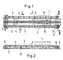
- Fig. 1 is a plan view of a conveyor track for general cargo 1 in the form of containers for luggage, which consists essentially of two parallel and spaced apart conveyors with longitudinal beams 2, on which in Conveying direction F seen behind each other and at a distance from each other conveyor rollers 3 or support rollers 4 for a conveyor belt 5 are mounted.
- the longitudinal beams 2 are C-shaped, each standing upright with their closed sides facing each other and connected to one another via a plurality of cross members 6, and connected to the floor via height-adjustable fastening elements (not shown).
- successive and spaced openings 8 are provided in the conveying direction F, through which feed rollers 3 or support rollers 4 project from below and are mounted on the webs of the longitudinal beams 2 about axes transverse to the conveying direction F and horizontally extending are.
- the conveyor rollers 3 are arranged on the right-hand side member 2 seen in the direction of conveyance F, which are designed as commercially available roller bearings with a rubber casing of the outer ring. This results in a low-noise running of the piece goods 1 over the conveyor rollers 3.
- the support rollers 4 are arranged on the left side member 2 seen in the conveying direction F and serve to support the conveyor belt 5, which is endlessly circumferential and is deflected at the beginning and at the end of the side member 2 via deflection wheels 9 which can be rotated about horizontal axes.
- the conveyor rollers 3 and the carrier rollers 4 are each arranged only in every second opening 8, wherein, viewed transversely to the conveying direction F, the conveyor rollers 4 are not arranged opposite each other and vice versa.
- a guide rail 10 is provided in the middle between the two longitudinal beams 2, which is fastened to the cross members 6 and for guiding the containers (piece goods 1) via a guide element arranged on the underside of the containers 11 (see FIG. 3).
- FIG. 2 shows a side view of FIG. 1, namely on the side of the longitudinal beam 2 with the support rollers 4 for the conveyor belt 5. It can be seen that the support rollers 4 are only arranged in every second opening 8. As a result, the left and right side members 2 can be made identical in terms of production technology.
- the lower run of the conveyor belt 5 is guided over two support rollers 12 arranged at a distance from one another in the conveying direction F.
- the respective deflection wheels 9 mounted at the ends of the longitudinal beams 2 are at one end via a not shown Drive can be driven.
- the non-driven deflection wheels 9 are mounted displaceably in the conveying direction F in order to be able to pretension the conveyor belt 5 via a schematically illustrated tensioning device 13.
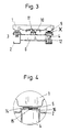
- Fig. 3 shows a cross section of Fig. 1 along the section line II, which can be seen that a pin-shaped guide element 11 is arranged on the container (piece goods 1), on the underside thereof, which in the guide rail 10 transversely to the conveying direction F is guided and is prevented from lifting off the conveyor track by this guide rail 10.
- Fig. 3 The enlargement of Fig. 3 from the area x of the support roller 4, which can be seen in Fig. 4, shows that the support roller 4 has a cylindrical peripheral surface without grooves and the conveyor belt 5 is designed as a toothed belt, which is also on the General cargo 1 side facing away and in the middle has a web 15 projecting downwards in the direction of the support roller 4 from the contour of the teeth 14 of the conveyor belt, which web is trapezoidal in cross section. It is also possible to use a toothed belt as the conveyor belt 5 without the web 15. This web 15, which runs in the longitudinal direction of the conveyor belt 5, is removed on the surface of the support roller 4 and has a height which prevents the teeth 14 of the conveyor belt 5 in Come into contact with the surface of the idlers 4. This results in a low-noise run of the conveyor belt 5. To guide the conveyor belt 5, flanges 16 are arranged on each side of the support rollers 4.
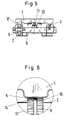
- FIG. 5 shows a cross section of FIG. 1 along the section line II-II. 5 from the region y shows that the deflection wheels 9 are designed as toothed disks, which additionally have a circumferential groove 17 in the middle for the web 15 of the conveyor belt 5.
- the driven deflection wheels 9 arranged on the other side of the longitudinal beam 2 are designed accordingly. It is also possible to design the non-driven deflection wheels 9 in accordance with the support rollers 4, that is to say with a cylindrical surface without a profile, in order to take advantage of this design with regard to the smooth running of the conveyor belt 5.
Abstract
Description
Die Erfindung betrifft eine Förderbahn für Stückgut, insbesondere für Gepäck-Behälter gemäß dem Oberbegriff des Anspruchs 1.The invention relates to a conveyor track for general cargo, in particular for luggage containers according to the preamble of
Aus der deutschen Patentschrift DE 44 07 163 C1 ist eine Förderanlage für Paletten zum Abstellen von Kraftfahrzeugen bekannt, die im wesentlichen aus zwei parallel und mit Abstand zueinander verlaufenden Fördergurten zum Transport der Paletten besteht. Die Fördergurte sind jeweils endlos umlaufend ausgebildet und werden am Anfang und am Ende der Förderbahn über um horizontale Achsen drehbare Umlenkräder geführt, die antriebsmäßig mit einem Elektromotor verbunden sind. Die Übertragung der Antriebskraft zwischen den Umlenkrädem und dem einen flachen Querschnitt aufweisenden Fördergurt erfolgt reibschlüssig. Die Umlenkräder sind jeweils an den Enden von zwei parallel und in Förderrichtung verlaufenden Längsträgem gelagert.From the German patent DE 44 07 163 C1, a conveyor system for pallets for parking motor vehicles is known, which essentially consists of two parallel and spaced apart conveyor belts for transporting the pallets. The conveyor belts are endlessly rotating and are guided at the beginning and at the end of the conveyor track via deflection wheels that can be rotated about horizontal axes and are connected to an electric motor in terms of drive. The transmission of the driving force between the deflection wheels and the conveyor belt, which has a flat cross-section, takes place in a frictional manner. The deflection wheels are each supported at the ends of two longitudinal beams running parallel and in the conveying direction.
In Förderrichtung gesehen zwischen den Umlenkrollen wird das obere Trum des Fördergurtes zusätzlich über Tragrollen abgestützt, die ebenfalls an den Längsträgern gelagert sind. Zur Seitenführung des Fördergurtes sind um senkrechte Achsen drehbare Führungsrollen bzw. seitlich neben dem Fördergurt sowie in Förderrichtung verlaufende Führungsschienen vorgesehen. Als weitere Möglichkeiten für die Führung des Fördergutes werden vorgeschlagen, entweder an den Tragrollen beidseitig Führungsscheiben anzuordnen, die Tragrollen ballig auszuführen oder die Tragrollen mit einer Umfangsnut zu versehen, über die ein komplementär ausgebildeter Steg geführt wird, der an der Unterseite des Fördergurtes angeordnet ist.Seen in the conveying direction between the deflection rollers, the upper run of the conveyor belt is additionally supported by idler rollers, which are also mounted on the longitudinal beams. For lateral guidance of the conveyor belt, guide rollers rotatable about vertical axes or laterally next to the conveyor belt and guide rails running in the conveying direction are provided. As further options for guiding the material to be conveyed, it is proposed either to arrange guide disks on both sides of the support rollers, to make the support rollers spherical, or to provide the support rollers with a circumferential groove over which a complementary web is guided, which is arranged on the underside of the conveyor belt.
Derartige Fördergurte müssen, um u.a. etwaigem Schlupf zwischen den angetriebenen Umlenkrädem und dem Gurt entgegenzuwirken, stark vorgespannt werden. Die Vorspannung erfolgt über Spannstationen, die entsprechend der erforderlichen Spannlänge verschiedene Baugrößen aufweisen müssen. Eine Vereinheitlichung der Spannstationen ist daher kaum möglich. Außerdem müssen diese hohen Spannkräfte von der Tragkonstruktion des Förderers aufgenommen werden und diese entsprechend dimensioniert werden. Darüber hinaus ist durch die reibschlüssige Antriebsart des Gurtes ein Gleichlauf der beiden parallelen Fördergurte nicht immer gewährleistet, so daß es zu einem Verdrehen der Paletten kommen kann, wodurch eine zuverlässige Übergabe an nachfolgende Förderer beeinträchtigt werden könnte.Conveyor belts of this type must, among other things, counteract any slippage between the driven deflection wheels and the belt, be strongly pretensioned. The pre-tensioning takes place via tensioning stations, which must have different sizes according to the required tensioning length. A standardization of the tensioning stations is therefore hardly possible. In addition, these high clamping forces have to be absorbed by the supporting structure of the conveyor and they have to be dimensioned accordingly. In addition, the frictional drive type of the belt does not always ensure synchronism of the two parallel conveyor belts, so that the pallets can be twisted, which could impair reliable transfer to subsequent conveyors.
Des weiteren zeigt die europäische Patentanmeldung EP 601 279 A1 bereits ein Laufband für Personen, das über zwei Keilriemen in Verbindung mit zwei Zahnriemen angetrieben wird. Das Laufband besteht im wesentlichen aus in Förderrichtung aufeinanderfolgenden sowie quer zur Förderrichtung ausgerichteten Trittlamellen, die mit ihren seitlichen Enden auf dem kombinierten Keil- und Zahnriemen befestigt sind. Das Laufband und somit die kombinierten Keil- und Zahnriemen sind endlos ausgebildet und laufen um jeweils am Anfang und am Ende des Laufbandes angeordnete Umlenkrollen um. Die Kombination von Keil- und Zahnriemen für den Antrieb des Laufbandes wurde in Abkehr eines für Laufbänder sonst üblich verwendeten reinen Zahnriemenantriebes gewählt, um die Hauptantriebskraft von den Umlenkrädem in den Keilriemen einzuleiten und den Zähnen des Keilriemens nur noch die Aufgabe der Synchronisation der beidendig von den kombinierten Keil- und Zahnriemen angetriebenen Trittlamellen zu gewährleisten. Hierdurch soll die hauptsächlich von den in die Zahnscheibe eintauchenden Zähnen des Zahnriemens hervorgerufene Geräuschentwicklung minimiert werden. Zur Optimierung der Geräuschminderung wurden gleichzeitig auf dem Umfang der Zahnscheiben zahnlose Abschnitte vorgesehen, die sich mit verzahnten Bereichen abwechseln sowie der Abstand der Flanken der Zähne auf der Zahnscheibe so vergrößert, daß nur eine Flanke des Zahns des Zahnriemens in Eingriff mit der Zahnscheibe gelangt. In bezug auf den Antrieb spielt der Zahnriemen nur noch eine untergeordnete Rolle, da seine Haupffunktion in der Synchronisation der schlupfbehafteten Keilriementriebe liegt.Furthermore, the European patent application EP 601 279 A1 already shows a treadmill for people which is driven by two V-belts in connection with two toothed belts. The treadmill essentially consists of successive slats in the conveying direction and aligned transversely to the conveying direction, which are attached with their lateral ends to the combined V-belt and toothed belt. The treadmill and thus the combined V-belts and toothed belts are endless and run around pulleys arranged at the beginning and at the end of the treadmill. The combination of V-belts and toothed belts for the drive of the treadmill was chosen in return for a pure toothed belt drive normally used for treadmills, in order to transfer the main driving force from the deflection wheels into the V-belt and the teeth of the V-belt only the task of synchronizing the both ends of the Combined V-belts and toothed belts to ensure driven tread slats. This is to minimize the noise that is mainly caused by the teeth of the toothed belt dipping into the toothed pulley. To optimize noise reduction, toothless sections were provided at the same time on the circumference of the toothed pulleys, alternating with toothed areas, and the distance between the flanks of the teeth on the toothed pulley was increased so that only one flank of the tooth of the toothed belt came into engagement with the toothed pulley. With regard to the drive, the toothed belt only plays a subordinate role, since its main function is the synchronization of the V-belt drives with slip.
Der vorliegenden Erfindung liegt die Aufgabe zugrunde, eine Förderbahn für Stückgut, insbesondere für Gepäck-Behälter, zu schaffen, die eine konstruktiv vereinfachte Bauweise aufweist.The present invention has for its object to provide a conveyor track for general cargo, especially for luggage containers, which has a structurally simplified design.
Diese Aufgabe wird bei einer Förderbahn für Stückgut, insbesondere für Gepäck-Behälter durch die im Anspruch 1 aufgeführten Merkmale gelöst. Vorteilhafte Ausgestaltungen der Erfindung sind in den Unteransprüchen 2 bis 8 angegeben.This object is achieved in a conveyor track for general cargo, in particular for luggage containers, by the features listed in
Die Lösung sieht vor, durch die Verwendung eines Zahnriemens als Fördergurt für den unmittelbaren Transport des Stückguts die Spannstationen konstruktiv einfacher auszugestalten, d.h. der zur Verfügung zu stellende Bereich möglicher Spannwege kann geringer ausfallen, da die Zahnriemen gegenüber den sonst üblich verwendeten Fördergurten eine geringere Längendehnung aufweisen, die im vorliegenden Fall etwa nur 0,2 % beträgt. Hierdurch können konstruktiv gleich ausgebildete Spannstationen für Förderbahnabschnitte im Bereich von einem bis 25 m verwendet werden. Darüber hinaus wird durch den Formschluß zwischen dem Zahnriemen und der Umlenkräder die Betriebssicherheit der Förderbahn erhöht, da kein Gurtschlupf und hierdurch hervorgerufene Störungen vorkommen können. Außerdem sind durch den Formschluß zwischen Zahnriemen und Zahnscheibe zur schlupffreien Übertragung der Antriebskräfte geringere Spannkräfte für den Riemen erforderlich als bei Flachgurten und reibschlüssiger Antriebskraftübertragung. Die geringeren Spannkräfte erlauben eine einfachere Ausbildung der Tragkonstruktion.The solution provides for the tensioning stations to be made structurally simpler by using a toothed belt as a conveyor belt for the direct transport of the piece goods, i.e. the range of possible tensioning paths to be made available can be smaller, since the toothed belts have a smaller elongation than the conveyor belts normally used, which in the present case is only about 0.2%. As a result, tensioning stations of identical design can be used for conveyor track sections in the range from one to 25 m. In addition, the operational safety of the conveyor track is increased by the positive connection between the toothed belt and the deflection wheels, since no belt slippage and the resulting malfunctions can occur. In addition, due to the positive connection between the toothed belt and toothed pulley, less tensioning forces are required for the belt for slip-free transmission of the drive forces than in the case of flat belts and frictional transmission of the drive force. The lower clamping forces allow a simpler design of the supporting structure.
Als vorteilhaft hat sich die Anordnung eines aus der Oberfläche des Fördergurtes hervorstehenden Steges auf der dem Stückgut abgewandten und der mit den Zähnen versehenen Seite des Fördergurtes erwiesen, da hierdurch eine gute Seitenführung des Fördergurtes im Bereich der Umlenkräder mit einer komplementär ausgebildeten umlaufenden Nut erreicht wird. Außerdem wird durch diesen Steg in Verbindung mit den Tragrollen, die eine zylindrische oder ballige Umfangsfläche aufweisen, ein durchgehender und somit gleichförmiger Lauf des Fördergurts auf der Tragrollenoberseite erreicht, da nur der Steg und nicht die Zähne des Fördergurtes auf der Umfangsfläche der Tragrolle ablaufen. Hierdurch wird gleichzeitig das Stückgut schonend gefördert. Auch wird hierdurch ein besonders lärmarmer Lauf des Fördergurtes erzielt und somit sind auch hohe Laufgeschwindigkeiten des Fördergurtes ohne störende Geräuschentwicklung möglich. Hieraus resultieren erreichbare Fördergeschwindigkeiten von etwa 5 m/s, wodurch derartige Förderbahnen sich insbesondere für Transferstrecken zur Förderung von Fluggepäck-Behältern eignen. Zur Führung des Fördergurtes können zusätzlich an den Tragrollen beidseitig Spurkränze vorgesehen werden. Die Ausbildung des Fördergurtes als Flachgurt mit rechteckigem Querschnitt ist für die Übertragung der Lasten des Stückguts auf die Tragrollen und der Antriebskräfte auf das Stückgut günstig.The arrangement of a web protruding from the surface of the conveyor belt on the side of the conveyor belt facing away from the piece goods and on the toothed side has proven to be advantageous, since this achieves good lateral guidance of the conveyor belt in the region of the deflection wheels with a complementary circumferential groove. In addition, this web in conjunction with the idlers, which have a cylindrical or spherical circumferential surface, ensures a continuous and thus uniform running of the conveyor belt on the top of the idler roller, since only the web and not the teeth of the conveyor belt run on the circumferential surface of the idler roller. As a result, the general cargo is conveyed gently. This also results in a particularly low-noise running of the conveyor belt and thus high running speeds of the conveyor belt are possible without disturbing noise. Result from this achievable conveying speeds of about 5 m / s, which makes such conveyors particularly suitable for transfer routes for conveying flight luggage containers. To guide the conveyor belt, wheel flanges can also be provided on both sides of the idlers. The design of the conveyor belt as a flat belt with a rectangular cross-section is favorable for the transmission of the loads of the piece goods to the idlers and the driving forces on the piece goods.
Als besonders vorteilhaft für den Transport des Stückgutes, insbesondere der Gepäck-Behälter, hat sich die Ausbildung der Förderbahn mit zwei parallel und voneinander beabstandeten sowie in Förderrichtung verlaufenden Förderem, von denen ein Förderer einen Zahnriemen und der andere Förderer hintereinander angeordnete und freilaufend ausgebildete Förderrollen aufweist, erwiesen, da hierdurch Gleichlaufschwankungen beim Zahnriemen nicht zu einer Schrägstellung des Stückguts führen. Des weiteren wird eine Beruhigung des Laufs des Stückguts auf dem Förderer dadurch erreicht, daß die Förderrollen und die Tragrollen für den Zahnriemen in Förderrichtung gesehen gegeneinander versetzt angeordnet sind.The formation of the conveyor track with two parallel and spaced apart and in the conveying direction conveyors, of which one conveyor has a toothed belt and the other conveyor arranged one behind the other and free-running conveyor rollers, has proven to be particularly advantageous for the transport of the piece goods, in particular the luggage container , proved that this means that synchronous fluctuations in the toothed belt do not lead to an inclined position of the piece goods. Furthermore, the running of the piece goods on the conveyor is calmed down by the fact that the conveyor rollers and the support rollers for the toothed belt are arranged offset with respect to one another in the conveying direction.
Besonders geeignet ist die vorliegende Förderbahn für den Transport von Behältern zur Aufnahme von Gepäck, wobei zusätzlich an der Unterseite der Behälter ein Führungselement angeordnet ist, das in einer in Förderrichtung gesehen zwischen den Förderrollen und dem Fördergurt verlaufenden Schiene geführt ist.The present conveyor track is particularly suitable for the transport of containers for holding luggage, a guide element being additionally arranged on the underside of the containers, which is seen in a rail running in the direction of conveyance between the conveyor rollers and the conveyor belt.
Die Erfindung wird nachfolgend anhand von den in den Zeichnungen dargestellten Ausführungsbeispielen näher beschrieben. Es zeigen:
- Fig. 1 eine Draufsicht auf eine Förderbahn für Gepäck-Behälter,
- Fig. 2 eine Seitenansicht von
Figur 1, - Fig. 3 eine Schnittansicht von
Figur 1 gemäß der Schnittlinie I-I, - Fig. 4 eine Ausschnittsvergrößerung von dem Bereich x der
Figur 3, - Fig. 5 eine Schnittansicht von
Figur 1 gemäß der Schnittlinie ll-ll, - Fig. 6 eine Ausschnittsvergrößerung von dem Bereich y der
Figur 5.
- 1 is a plan view of a conveyor track for luggage containers,
- 2 shows a side view of FIG. 1,
- 3 is a sectional view of Figure 1 along the section line II,
- 4 shows an enlargement of the area x of FIG. 3,
- 5 is a sectional view of Figure 1 along the section line II-II,
- 6 shows an enlarged detail of area y of FIG. 5.
In Fig. 1 ist eine Draufsicht auf eine Förderbahn für Stückgut 1 in Form von Behältern für Gepäckstücke dargestellt, die im wesentlichen aus zwei parallel und mit Abstand zueinander verlaufenden Förderern mit Längsträgern 2 besteht, an denen in Förderrichtung F gesehen hintereinander und mit Abstand zueinander Förderrollen 3 oder Tragrollen 4 für einen Fördergurt 5 gelagert sind. Die Längsträger 2 sind C-förmig ausgebildet, jeweils aufrecht stehend mit ihren geschlossenen Seiten einander zugewandt und über mehrere Quertraversen 6 miteinander verbunden, sowie über nicht dargestellte höheneinstellbare Befestigungselemente mit dem Boden verbunden. In den Obergurten 7 der Längsträger 2 sind in Förderrichtung F aufeinander folgende und voneinander beabstandet angeordnete Öffnungen 8 vorgesehen, durch die von unten Förderrollen 3 bzw. Tragrollen 4 hindurchragen, die an den Stegen der Längsträger 2 um quer zur Förderrichtung F und horizontal verlaufende Achsen gelagert sind. Die Förderrollen 3 sind an dem in Förderrichtung F gesehen rechten Längsträger 2 angeordnet, die als handelsübliche Wälzlager mit einer Gummiummantelung des Außenringes ausgebildet sind. Hierdurch wird ein geräuscharmer Lauf des Stückgutes 1 über die Förderrollen 3 erzielt. Die Tragrollen 4 sind an dem in Förderrichtung F gesehen linken Längsträger 2 angeordnet und dienen zur Abstützung des Fördergurtes 5, der endlos umlaufend ausgebildet ist und am Anfang und am Ende des Längsträgers 2 über Umlenkräder 9, die um horizontale Achsen drehbar sind, umgelenkt wird.In Fig. 1 is a plan view of a conveyor track for
Hierbei sind die Förderrollen 3 und die Tragrollen 4 jeweils nur in jeder zweiten Öffnung 8 angeordnet, wobei quer zur Förderrichtung F gesehen jeweils den Tragrollen 4 keine Förderrollen 3 gegenüberliegend angeordnet sind und umgekehrt.Here, the
Des weiteren ist der Fig. 1 zu entnehmen, daß in der Mitte zwischen den beiden Längsträgern 2 eine Führungsschiene 10 vorgesehen ist, die auf den Quertraversen 6 befestigt ist und zur Führung der Behälter (Stückgut 1) über ein an der Unterseite der Behälters angeordnetes Führungselement 11 (s. Fig. 3) dient.1 that a
Die Fig. 2 zeigt eine Seitenansicht von der Fig. 1, und zwar auf die Seite des Längsträgers 2 mit den Tragrollen 4 für den Fördergurt 5. Es ist ersichtlich, daß die Tragrollen 4 jeweils nur in jeder zweiten Öffnung 8 angeordnet sind. Hierdurch können die linken und rechten Längsträger 2 fertigungstechnisch gleich ausgebildet werden. Das Untertrum des Fördergurtes 5 wird, um ein Durchhängen und ein Schleifen auf dem Boden zu vermeiden, über zwei in Förderrichtung F mit Abstand zueinander angeordnete Stützrollen 12 geführt. Die jeweils an den Enden der Längsträger 2 gelagerten Umlenkräder 9 sind nur an einem Ende über einen nicht dargestellten Antrieb antreibbar. Die nicht angetriebenen Umlenkräder 9 sind in Förderrichtung F verschiebbar gelagert, um über eine schematisch dargestellte Spannvorrichtung 13 den Fördergurt 5 vorspannen zu können.FIG. 2 shows a side view of FIG. 1, namely on the side of the
Die Fig. 3 zeigt einen Querschnitt von Fig. 1 entlang der Schnittlinie I-I, der zu entnehmen ist, daß an dem Behälter (Stückgut 1), und zwar an dessen Unterseite ein stiftförmiges Führungselement 11 angeordnet ist, das in der Führungsschiene 10 quer zur Förderrichtung F geführt ist sowie durch diese Führungsschiene 10 von einem Abheben von der Förderbahn gehindert wird.Fig. 3 shows a cross section of Fig. 1 along the section line II, which can be seen that a pin-shaped
Die Ausschnittsvergrößerung von Fig. 3 aus dem Bereich x der Tragrolle 4, die in Fig. 4 zu sehen ist, zeigt, daß die Tragrolle 4 eine zylindrische Umfangsfläche ohne eingearbeitete Nuten aufweist und der Fördergurt 5 als Zahnriemen ausgebildet ist, der zusätzlich auf der dem Stückgut 1 abgewandten Seite und mittig einen nach unten in Richtung der Tragrolle 4 aus der Kontur der Zähne 14 des Fördergurts herausragenden Steg 15 aufweist, der im Querschnitt trapezförmig ausgebildet ist. Es ist auch möglich, als Fördergurt 5 einen Zahnriemen ohne den Steg 15 zu verwenden Dieser in Längsrichtung des Fördergurtes 5 verlaufende Steg 15 wird auf der Oberfläche der Tragrolle 4 abgetragen und weist eine Höhe auf, die verhindert, daß die Zähne 14 des Fördergurtes 5 in Kontakt mit der Oberfläche der Tragrollen 4 kommen. Hierdurch wird ein lärmarmer Lauf des Fördergurtes 5 erzielt. Zur Führung des Fördergurtes 5 sind an den Tragrollen 4 jeweils seitlich Spurkränze 16 angeordnet.The enlargement of Fig. 3 from the area x of the
Ferner ist in der Fig. 5 ein Querschnitt von Fig. 1 entlang der Schnittlinie ll-ll gezeigt. Der Ausschnittsvergrößerung von Fig. 5 aus dem Bereich y ist zu entnehmen, daß die Umlenkräder 9 als Zahnscheiben ausgebildet sind, die zusätzlich in der Mitte eine umlaufende Nut 17 für den Steg 15 des Fördergurtes 5 aufweisen. Die auf der anderen Seite des Längsträgers 2 angeordneten angetriebenen Umlenkräder 9 sind entsprechend ausgebildet. Es ist auch möglich die nicht angetriebenen Umlenkräder 9 entsprechend den Tragrollen 4, also mit profilloser, zylindrischer Oberfläche auszubilden, um die Vorteile dieser Ausbildung bezüglich des ruhigen Laufs des Fördergurtes 5 zu nutzen.5 shows a cross section of FIG. 1 along the section line II-II. 5 from the region y shows that the
- 11
- StückgutGeneral cargo
- 22nd
- LängsträgerSide member
- 33rd
- FörderrollenConveyor rollers
- 44th
- TragrollenIdlers
- 55
- FördergurtConveyor belt
- 66
- QuertraverseCrossbar
- 77
- ObergurtTop chord
- 88th
- Öffnungenopenings
- 99
- UmlenkräderDeflection wheels
- 1010th
- FührungsschieneGuide rail
- 1111
- FührungselementGuide element
- 1212th
- StützrolleSupport roller
- 1313
- SpannvorrichtungJig
- 1414
- Zähneteeth
- 1515
- Stegweb
- 1616
- SpurkränzeWheel flanges
- 1717th
- NutGroove
- FF
- FörderrichtungDirection of conveyance
- xx
- AusschnittsbereichClipping area
- yy
- AusschnittsbereichClipping area
Claims (8)
dadurch gekennzeichnet,
daß der Fördergurt (5) als Zahnriemen ausgebildet ist, dessen Zähne auf der dem Stückgut (1) abgewandten Seite angeordnet sind, und daß mindestens die angetriebenen Umlenkräder (9) als Zahnscheiben ausgebildet sind.Conveyor track for piece goods (1), in particular for luggage containers, with at least two conveyors carrying the piece goods (1) and spaced apart from one another and running parallel in the conveying direction (F), at least one of which is a driven, endlessly rotating and via deflection wheels (9) guided and designed as a flat belt conveyor belt (5), which is supported by viewed in the conveying direction (F) one behind the other and between the deflection wheels (9) arranged support rollers (4),
characterized,
that the conveyor belt (5) is designed as a toothed belt, the teeth of which are arranged on the side facing away from the piece goods (1), and that at least the driven deflection wheels (9) are designed as toothed disks.
dadurch gekennzeichnet,
daß der Fördergurt (5) auf der gezahnten Seite einen aus der Oberfläche des Fördergurtes (5) hervorstehenden Steg (15) aufweist, der parallel zur Längserstreckung des Fördergurtes (5) verläuft und von den zylindrisch oder ballig ausgebildetenTragrollen (4) abtragbar ist, deren Umfangsflächen von den Zähnen des Fördergurtes (5) beabstandet sind.Device according to claim 1,
characterized,
that the conveyor belt (5) has on the toothed side a web (15) projecting from the surface of the conveyor belt (5), which web runs parallel to the longitudinal extent of the conveyor belt (5) and can be removed from the cylindrical or spherical support rollers (4), the Circumferential surfaces are spaced from the teeth of the conveyor belt (5).
dadurch gekennzeichnet,
daß in die Umlenkräder (9) jeweils komplementär zu dem Steg (15) ausgebildete Umfangsnuten (17) eingearbeitet sind.Device according to claim 2,
characterized,
that in the deflection wheels (9) are complementary to the web (15) formed circumferential grooves (17).
dadurch gekennzeichnet,
daß an den Tragrollen (4) beidseitig Spurkränze (16) angeordnet sind.Device according to one of claims 1 to 3,
characterized,
that on the support rollers (4) wheel flanges (16) are arranged on both sides.
dadurch gekennzeichnet,
daß für den Transport des Stückguts (1) die Förderbahn einen Förderer mit einem Fördergurt (5) und einen weiteren Förderer mit Förderrollen (3) aufweist.Device according to one of claims 1 to 4
characterized,
that for the transport of the piece goods (1) the conveyor track has a conveyor with a conveyor belt (5) and another conveyor with conveyor rollers (3).
dadurch gekennzeichnet,
daß die Förderrollen (3) freilaufend sind.Device according to claim 5,
characterized,
that the conveyor rollers (3) are free running.
dadurch gekennzeichnet,
daß in Förderrichtung (F) gesehen die Förderrollen (3) und die Tragrollen (4) gegeneinander versetzt angeordnet sind.Apparatus according to claim 5 or 6,
characterized,
that seen in the conveying direction (F), the conveyor rollers (3) and the support rollers (4) are arranged offset from one another.
dadurch gekennzeichnet,
daß die Förderbahn für den Transport von Behältem (Stückgut 1) vorgesehen ist, an deren Unterseite ein Führungselement (11) angeordnet ist, das in einer in Förderrichtung (F) gesehen zwischen den Förderem verlaufenden Schiene (10) geführt ist.Device according to one of claims 5 to 7,
characterized,
that the conveyor track is provided for the transport of containers (piece goods 1), on the underside of which a guide element (11) is arranged, which is guided in a rail (10) running in the conveying direction (F) between the conveyors.
Applications Claiming Priority (2)
| Application Number | Priority Date | Filing Date | Title |
|---|---|---|---|
| DE19616907 | 1996-04-16 | ||
| DE19616907A DE19616907C5 (en) | 1996-04-16 | 1996-04-16 | Conveyor track for general cargo, especially for luggage containers |
Publications (4)
| Publication Number | Publication Date |
|---|---|
| EP0802129A2 true EP0802129A2 (en) | 1997-10-22 |
| EP0802129A3 EP0802129A3 (en) | 1998-07-08 |
| EP0802129B1 EP0802129B1 (en) | 2001-05-23 |
| EP0802129B2 EP0802129B2 (en) | 2005-08-31 |
Family
ID=7792636
Family Applications (1)
| Application Number | Title | Priority Date | Filing Date |
|---|---|---|---|
| EP97250117A Expired - Lifetime EP0802129B2 (en) | 1996-04-16 | 1997-04-15 | Conveyor path for articles, especially for luggage containers |
Country Status (4)
| Country | Link |
|---|---|
| US (1) | US6070714A (en) |
| EP (1) | EP0802129B2 (en) |
| DE (2) | DE19616907C5 (en) |
| DK (1) | DK0802129T4 (en) |
Cited By (8)
| Publication number | Priority date | Publication date | Assignee | Title |
|---|---|---|---|---|
| NL1009222C2 (en) * | 1998-05-20 | 1999-11-24 | Vanderlande Ind Nederland | Method and installation for transporting goods and combination of a container and a wheel-supported frame for transporting goods. |
| EP1101714A1 (en) * | 1999-11-18 | 2001-05-23 | mechatronik Gesellschaft zur Entwicklung, und Anwendung von Mechanik und Mikroelektronic mbH | Conveyor system for transport containers |
| DE10032189A1 (en) * | 2000-07-01 | 2002-01-17 | Bosch Gmbh Robert | Conveyor for piece goods has two parallel supports on which are conveyor elements, belt, pulley stringer , rollers in grooves. |
| DE19616907C5 (en) * | 1996-04-16 | 2004-02-19 | Siemens Ag | Conveyor track for general cargo, especially for luggage containers |
| EP1400468A1 (en) * | 2002-09-17 | 2004-03-24 | Siemens Aktiengesellschaft | Conveyor path for articles, especially for luggage containers |
| EP1477433A1 (en) | 2003-05-15 | 2004-11-17 | Siemens Aktiengesellschaft | Conveyor system for containers, in particular an airport baggage conveyor system, as well as a convex curved upward slope for a conveyor system |
| DE102005036962B3 (en) * | 2005-08-05 | 2007-02-01 | Siemens Ag | Rising section for baggage conveyor has side plates compiled from several polygonally aligned connected and angled pieces |
| DE202005019111U1 (en) * | 2005-12-06 | 2007-04-19 | Krones Ag | Belt for transporting vessels |
Families Citing this family (12)
| Publication number | Priority date | Publication date | Assignee | Title |
|---|---|---|---|---|
| DE10032188B4 (en) * | 2000-07-01 | 2004-04-08 | Robert Bosch Gmbh | Conveyor system for general cargo, especially workpiece carriers |
| US6896125B2 (en) * | 2003-04-04 | 2005-05-24 | Pflow Industries, Inc. | Belt attachment device and method |
| DE10318621A1 (en) | 2003-04-24 | 2004-11-25 | Siemens Ag | Conveyor for the transport of load carriers |
| DE10320963A1 (en) * | 2003-05-09 | 2004-12-16 | Siemens Ag | Conveyor system, in particular an airport baggage conveyor system, and an unloading device of a conveyor system for containers for transporting goods, in particular luggage |
| DE102005024434B4 (en) * | 2005-05-24 | 2009-07-16 | Knapp Logistik Automation Ges.M.B.H. | Curve conveyor with endless conveyor belt for conveying piece goods |
| DE102006053913B4 (en) * | 2006-11-16 | 2009-11-26 | Eisenmann Anlagenbau Gmbh & Co. Kg | Conveyor for load carriers |
| DE102007023219A1 (en) * | 2007-05-18 | 2008-11-20 | Siemens Ag | Aircraft baggage-conveyor system, has guide rails corresponding to one of guiding channels of cylinder in effective position, where guide rails run before and after deflector in transporting direction |
| DE102008037036B4 (en) * | 2008-08-08 | 2011-12-15 | Eisenmann Ag | Device for drying objects with at least one pulling means |
| DE102009023287A1 (en) | 2009-05-29 | 2010-12-02 | Krones Ag | Belt conveyor |
| CN104379460B (en) * | 2012-05-29 | 2017-02-22 | 西门子公司 | Container for transporting items of luggage in a sorting system and sorting system |
| DE102012020789B4 (en) | 2012-10-24 | 2024-03-07 | Volkswagen Aktiengesellschaft | Timing belt drive |
| CN104309987A (en) * | 2014-09-10 | 2015-01-28 | 常熟市古里镇淼泉利达机械厂 | Cloth conveyer |
Citations (13)
| Publication number | Priority date | Publication date | Assignee | Title |
|---|---|---|---|---|
| FR718485A (en) | 1931-06-10 | 1932-01-25 | Magneto Lumiere L M C | Pulley and belt transmission device |
| GB885427A (en) | 1960-06-14 | 1961-12-28 | Edric Raymond Brooke | Improvements relating to belt transmissions |
| DE1650657A1 (en) | 1968-01-10 | 1970-11-05 | Continental Gummi Werke Ag | Toothed belt drive |
| DE2654859A1 (en) | 1975-12-08 | 1977-06-23 | Rapistan Van Der Lande Bv | DEVICE WITH ONE DRIVE |
| DE2609043A1 (en) | 1976-03-05 | 1977-09-08 | Helmut Klinkicht | Ribbed conveyor belt for fruit picking machine - has transverse ribs at outside and longitudinal ribs at inside to hold fruit and give guidance |
| EP0036958B1 (en) | 1980-03-29 | 1986-09-24 | Robert Bosch Gmbh | Supporting member for belt conveyors |
| EP0364992A2 (en) | 1988-10-21 | 1990-04-25 | Woodway Ag | Endless running belt for fitness training |
| DE3836952A1 (en) | 1988-10-29 | 1990-05-03 | Matthias Malatitsch | Pallet conveyor |
| DE3933847A1 (en) | 1988-10-10 | 1990-05-31 | Volvo Ab | TIMING BELT DRIVE, ESPECIALLY FOR COMBUSTION ENGINES |
| DE4011317C2 (en) | 1990-04-07 | 1992-05-07 | Stotz, Kraemer Ag, 7014 Kornwestheim, De | |
| EP0569073A1 (en) | 1992-05-08 | 1993-11-10 | Vanderlande Industries Nederland B.V. | A conveyor |
| EP0601279A1 (en) | 1992-11-12 | 1994-06-15 | Woodway Ag | Toothed belt and V-belt apparatus for conveyors |
| DE4407163C1 (en) | 1994-03-04 | 1995-06-01 | Woehr Otto Gmbh | Vehicle conveyor for parking pallets |
Family Cites Families (17)
| Publication number | Priority date | Publication date | Assignee | Title |
|---|---|---|---|---|
| US207626A (en) * | 1878-09-03 | Improvement in belting for wool-washers | ||
| US2895593A (en) * | 1955-06-09 | 1959-07-21 | Rapids Standard Co Inc | Conveyors |
| US3082858A (en) * | 1961-08-03 | 1963-03-26 | Conveyor Systems | Belt conveyor system |
| US3312330A (en) * | 1963-08-30 | 1967-04-04 | Juengel V Matic Systems Inc | Conveyor apparatus |
| US3360105A (en) * | 1965-07-24 | 1967-12-26 | Beteiligungsund Patentverwaltu | Conveyor belt installation |
| US3428168A (en) * | 1967-02-02 | 1969-02-18 | Union Carbide Corp | Getter construction |
| US3561623A (en) * | 1969-01-07 | 1971-02-09 | Webb Co Jervis B | Article-handling system for baggage or other cargo |
| DE2107491C3 (en) * | 1971-02-17 | 1973-11-15 | Mannesmann Ag, 4000 Duesseldorf | Ramp start of a roller conveyor, especially for hand luggage in airport facilities |
| DE2124289C3 (en) * | 1971-05-15 | 1974-04-25 | Mannesmann Ag, 4000 Duesseldorf | Backlog of a transport system with pallets permanently connected to the system |
| SE384486B (en) * | 1973-07-09 | 1976-05-10 | T R L Holmqvist | BELT TRANSPORTER |
| US4204673A (en) * | 1978-12-14 | 1980-05-27 | Speer John Sr | Dual-tread exerciser |
| DE3900341A1 (en) * | 1989-01-07 | 1990-07-12 | Fredenhagen Kg | METHOD AND DEVICE FOR TRANSPORTING GOODS |
| DE3909949C2 (en) * | 1989-03-25 | 1993-12-23 | Breco Kunststoff | Belt drive consisting of a toothed belt and a toothed pulley |
| US5029697A (en) * | 1989-07-19 | 1991-07-09 | Simplimatic Engineering Company | Clean room conveyor |
| US5123517A (en) * | 1990-10-30 | 1992-06-23 | Lake Erie Welding & Fabricating | Low profile unpowered conveyor and method |
| DE19616907C5 (en) * | 1996-04-16 | 2004-02-19 | Siemens Ag | Conveyor track for general cargo, especially for luggage containers |
| DE29622845U1 (en) * | 1996-04-16 | 1997-07-03 | Mannesmann Ag | Conveyor track for general cargo, especially for luggage containers |
-
1996
- 1996-04-16 DE DE19616907A patent/DE19616907C5/en not_active Expired - Fee Related
-
1997
- 1997-04-02 US US08/831,229 patent/US6070714A/en not_active Expired - Lifetime
- 1997-04-15 EP EP97250117A patent/EP0802129B2/en not_active Expired - Lifetime
- 1997-04-15 DE DE59703578T patent/DE59703578D1/en not_active Expired - Lifetime
- 1997-04-15 DK DK97250117T patent/DK0802129T4/en active
Patent Citations (15)
| Publication number | Priority date | Publication date | Assignee | Title |
|---|---|---|---|---|
| FR718485A (en) | 1931-06-10 | 1932-01-25 | Magneto Lumiere L M C | Pulley and belt transmission device |
| GB885427A (en) | 1960-06-14 | 1961-12-28 | Edric Raymond Brooke | Improvements relating to belt transmissions |
| DE1650657A1 (en) | 1968-01-10 | 1970-11-05 | Continental Gummi Werke Ag | Toothed belt drive |
| DE2654859A1 (en) | 1975-12-08 | 1977-06-23 | Rapistan Van Der Lande Bv | DEVICE WITH ONE DRIVE |
| DE2609043A1 (en) | 1976-03-05 | 1977-09-08 | Helmut Klinkicht | Ribbed conveyor belt for fruit picking machine - has transverse ribs at outside and longitudinal ribs at inside to hold fruit and give guidance |
| EP0036958B1 (en) | 1980-03-29 | 1986-09-24 | Robert Bosch Gmbh | Supporting member for belt conveyors |
| DE3933847A1 (en) | 1988-10-10 | 1990-05-31 | Volvo Ab | TIMING BELT DRIVE, ESPECIALLY FOR COMBUSTION ENGINES |
| EP0364992A2 (en) | 1988-10-21 | 1990-04-25 | Woodway Ag | Endless running belt for fitness training |
| DE3836952A1 (en) | 1988-10-29 | 1990-05-03 | Matthias Malatitsch | Pallet conveyor |
| DE4011317C2 (en) | 1990-04-07 | 1992-05-07 | Stotz, Kraemer Ag, 7014 Kornwestheim, De | |
| EP0569073A1 (en) | 1992-05-08 | 1993-11-10 | Vanderlande Industries Nederland B.V. | A conveyor |
| EP0601279A1 (en) | 1992-11-12 | 1994-06-15 | Woodway Ag | Toothed belt and V-belt apparatus for conveyors |
| DE4238252C2 (en) | 1992-11-12 | 1994-08-18 | Woodway Ag | Toothed and V-belt device for treadmills |
| EP0601279B1 (en) | 1992-11-12 | 1997-11-05 | Woodway Ag | Toothed belt and V-belt apparatus for conveyors |
| DE4407163C1 (en) | 1994-03-04 | 1995-06-01 | Woehr Otto Gmbh | Vehicle conveyor for parking pallets |
Non-Patent Citations (9)
| Title |
|---|
| BEUMER-Zeichnung Nr. 7/8219-1-D vom 21.05.1990 |
| BEUMER-Zeichnung Nr.100-0009 vom 21.05.1985 |
| H.GRÜNHAGEN: "PUR-Zahnriemen für viele Standardlösungen - Innovatives Antriebselement", INDUSTRIE-ANZEIGER, no. 44, 1990, pages 20 - 24 |
| H.HAURI: "Zahnriemenantriebe", TECHNISCHE RUNDSCHAU, no. 11, 13 March 1979 (1979-03-13), pages 25 - 32 |
| Katalog Mulco "Aus Erfahrung erste Wahl" Druckvermerck 2/95 |
| KATALOG MULCO "Spurzahnbänder und Spurzahnscheiben" Druckvermerk: 2/95 |
| R.PERNEDER, A.SCHMID: "Der Zahnriemen, ein Innovatives Antriebselement", TECHNISCHE RUNDSCHAU, no. 10, 1988, pages 30 - 38 |
| W.BEITZ, K.-H.KÜTTNER: "DUBBEL - TASCHENBUCH FÜR DEN MASCHINENBAU", vol. 17, SPRINGER-VERLAG |
| Wieland-Katalog "Wieland Antriebstechnik, Zahnriemen - Antriebe"Auszug: 3 B1, Druckvermerck: 1/87 |
Cited By (12)
| Publication number | Priority date | Publication date | Assignee | Title |
|---|---|---|---|---|
| DE19616907C5 (en) * | 1996-04-16 | 2004-02-19 | Siemens Ag | Conveyor track for general cargo, especially for luggage containers |
| NL1009222C2 (en) * | 1998-05-20 | 1999-11-24 | Vanderlande Ind Nederland | Method and installation for transporting goods and combination of a container and a wheel-supported frame for transporting goods. |
| WO1999059901A3 (en) * | 1998-05-20 | 2000-02-10 | Vanderlande Ind Nederland | Method and installation for transporting goods, as well as a combination of a container and a wheel-supported frame for transporting goods |
| EP1101714A1 (en) * | 1999-11-18 | 2001-05-23 | mechatronik Gesellschaft zur Entwicklung, und Anwendung von Mechanik und Mikroelektronic mbH | Conveyor system for transport containers |
| DE10032189A1 (en) * | 2000-07-01 | 2002-01-17 | Bosch Gmbh Robert | Conveyor for piece goods has two parallel supports on which are conveyor elements, belt, pulley stringer , rollers in grooves. |
| DE10032189B4 (en) * | 2000-07-01 | 2004-04-01 | Robert Bosch Gmbh | Conveyor line for piece goods, especially workpiece carriers |
| EP1400468A1 (en) * | 2002-09-17 | 2004-03-24 | Siemens Aktiengesellschaft | Conveyor path for articles, especially for luggage containers |
| EP1477433A1 (en) | 2003-05-15 | 2004-11-17 | Siemens Aktiengesellschaft | Conveyor system for containers, in particular an airport baggage conveyor system, as well as a convex curved upward slope for a conveyor system |
| DE10321915B3 (en) * | 2003-05-15 | 2005-06-09 | Siemens Ag | Slope for a container conveyor system, in particular an airport baggage conveyor system |
| US7048109B2 (en) | 2003-05-15 | 2006-05-23 | Siemens Aktiengesellschaft | Transport system for containers, in particular an airport baggage handling system, and incline conveyor for a transport system |
| DE102005036962B3 (en) * | 2005-08-05 | 2007-02-01 | Siemens Ag | Rising section for baggage conveyor has side plates compiled from several polygonally aligned connected and angled pieces |
| DE202005019111U1 (en) * | 2005-12-06 | 2007-04-19 | Krones Ag | Belt for transporting vessels |
Also Published As
| Publication number | Publication date |
|---|---|
| EP0802129B2 (en) | 2005-08-31 |
| DE19616907A1 (en) | 1997-10-23 |
| DE19616907C5 (en) | 2004-02-19 |
| DE19616907C2 (en) | 2000-12-21 |
| DK0802129T3 (en) | 2001-08-06 |
| US6070714A (en) | 2000-06-06 |
| EP0802129B1 (en) | 2001-05-23 |
| DE59703578D1 (en) | 2001-06-28 |
| DK0802129T4 (en) | 2005-12-19 |
| EP0802129A3 (en) | 1998-07-08 |
Similar Documents
| Publication | Publication Date | Title |
|---|---|---|
| EP0802129A2 (en) | Conveyer path for articles, especially for luggage containers | |
| EP0704390A1 (en) | Conveyor system, in particular for load carriers for application in a medical laboratory | |
| DE3623435A1 (en) | COLLECTOR FOR RECEIVING OBJECTS WHERE THE OBJECT IS DELIVERED ONLY TO A WORKSTATION READY TO RECORD | |
| DE10340868B4 (en) | Conveyor system, in particular an airport baggage conveyor system, for the transport of general cargo serving containers | |
| EP0541850B1 (en) | Curvilinear plate conveyor | |
| DE2754918C2 (en) | Device for producing the same distances between piece goods on a conveyor belt | |
| EP2314529A2 (en) | Transport unit with accumulation roll chain | |
| EP0858961B1 (en) | Conveyer path with V-ribbed belt for articles, especially for luggage containers | |
| DE3439966A1 (en) | TRANSPORT DEVICE FOR STUECKGUETER OR THE LIKE | |
| DE2360335C2 (en) | Device for the transport and simultaneous spreading of a web of material | |
| EP1471016A1 (en) | Device for discharging load carriers | |
| DE10340867B4 (en) | Conveyor system, in particular an airport baggage conveyor system | |
| DE3023389C2 (en) | Friction roller conveyor | |
| DE19716748C1 (en) | Circulating conveyor for containers or palettes | |
| EP0683118B1 (en) | Storage device for article especially storage containers | |
| DE10044048B4 (en) | Device for transferring means of transport | |
| EP0949163A1 (en) | Installation for conveying goods by means of an endless conveyor belt or similar | |
| CH683989A5 (en) | Drive for endless transport chain | |
| DE10243117B4 (en) | Conveyor for general cargo, in particular for luggage containers | |
| DE3638661C1 (en) | Helical roller conveyor | |
| EP0562543B1 (en) | Transporting device for workpiece-carriers | |
| DE1945405C3 (en) | Device for branching a stream of brick blanks into two partial streams | |
| DE2534437A1 (en) | Conveying equipment for beamlike work pieces - has equipment for conveying work pieces across roller track and placing them longitudinally | |
| DE1434753C (en) | Device for the vertical and / or horizontal and / or inclined transport of vehicles, in particular in garages | |
| EP0401572B1 (en) | Transport device for supplying empty bobbins to spinning units and for removing full bobbins from spinning units of a double sided spinning machine, in particular a ring spinning machine |
Legal Events
| Date | Code | Title | Description |
|---|---|---|---|
| PUAI | Public reference made under article 153(3) epc to a published international application that has entered the european phase |
Free format text: ORIGINAL CODE: 0009012 |
|
| AK | Designated contracting states |
Kind code of ref document: A2 Designated state(s): DE DK FR GB IT NL |
|
| TPAD | Observations filed by third parties |
Free format text: ORIGINAL CODE: EPIDOS TIPA |
|
| TPAD | Observations filed by third parties |
Free format text: ORIGINAL CODE: EPIDOS TIPA |
|
| TPAD | Observations filed by third parties |
Free format text: ORIGINAL CODE: EPIDOS TIPA |
|
| PUAL | Search report despatched |
Free format text: ORIGINAL CODE: 0009013 |
|
| AK | Designated contracting states |
Kind code of ref document: A3 Designated state(s): DE DK FR GB IT NL |
|
| RHK1 | Main classification (correction) |
Ipc: B65G 15/10 |
|
| RTI1 | Title (correction) | ||
| 17P | Request for examination filed |
Effective date: 19980716 |
|
| 17Q | First examination report despatched |
Effective date: 19990723 |
|
| GRAG | Despatch of communication of intention to grant |
Free format text: ORIGINAL CODE: EPIDOS AGRA |
|
| GRAG | Despatch of communication of intention to grant |
Free format text: ORIGINAL CODE: EPIDOS AGRA |
|
| GRAH | Despatch of communication of intention to grant a patent |
Free format text: ORIGINAL CODE: EPIDOS IGRA |
|
| RAP1 | Party data changed (applicant data changed or rights of an application transferred) |
Owner name: ATECS MANNESMANN AG |
|
| GRAH | Despatch of communication of intention to grant a patent |
Free format text: ORIGINAL CODE: EPIDOS IGRA |
|
| GRAA | (expected) grant |
Free format text: ORIGINAL CODE: 0009210 |
|
| AK | Designated contracting states |
Kind code of ref document: B1 Designated state(s): DE DK FR GB IT NL |
|
| GBT | Gb: translation of ep patent filed (gb section 77(6)(a)/1977) |
Effective date: 20010523 |
|
| REF | Corresponds to: |
Ref document number: 59703578 Country of ref document: DE Date of ref document: 20010628 |
|
| ITF | It: translation for a ep patent filed |
Owner name: GUZZI E RAVIZZA S.R.L. |
|
| REG | Reference to a national code |
Ref country code: DK Ref legal event code: T3 |
|
| ET | Fr: translation filed | ||
| REG | Reference to a national code |
Ref country code: GB Ref legal event code: IF02 |
|
| PLBQ | Unpublished change to opponent data |
Free format text: ORIGINAL CODE: EPIDOS OPPO |
|
| PLBI | Opposition filed |
Free format text: ORIGINAL CODE: 0009260 |
|
| PLBF | Reply of patent proprietor to notice(s) of opposition |
Free format text: ORIGINAL CODE: EPIDOS OBSO |
|
| 26 | Opposition filed |
Opponent name: BEUMER MASCHINENFABRIK GMBH & CO. KG Effective date: 20020222 |
|
| RAP2 | Party data changed (patent owner data changed or rights of a patent transferred) |
Owner name: SIEMENS AKTIENGESELLSCHAFT |
|
| NLR1 | Nl: opposition has been filed with the epo |
Opponent name: BEUMER MASCHINENFABRIK GMBH & CO. KG |
|
| NLT2 | Nl: modifications (of names), taken from the european patent patent bulletin |
Owner name: SIEMENS AKTIENGESELLSCHAFT |
|
| PLBF | Reply of patent proprietor to notice(s) of opposition |
Free format text: ORIGINAL CODE: EPIDOS OBSO |
|
| PLAY | Examination report in opposition despatched + time limit |
Free format text: ORIGINAL CODE: EPIDOSNORE2 |
|
| PLBC | Reply to examination report in opposition received |
Free format text: ORIGINAL CODE: EPIDOSNORE3 |
|
| PUAH | Patent maintained in amended form |
Free format text: ORIGINAL CODE: 0009272 |
|
| STAA | Information on the status of an ep patent application or granted ep patent |
Free format text: STATUS: PATENT MAINTAINED AS AMENDED |
|
| 27A | Patent maintained in amended form |
Effective date: 20050831 |
|
| AK | Designated contracting states |
Kind code of ref document: B2 Designated state(s): DE DK FR GB IT NL |
|
| NLR2 | Nl: decision of opposition |
Effective date: 20050831 |
|
| REG | Reference to a national code |
Ref country code: DK Ref legal event code: T4 |
|
| REG | Reference to a national code |
Ref country code: GB Ref legal event code: 732E |
|
| GBTA | Gb: translation of amended ep patent filed (gb section 77(6)(b)/1977) | ||
| NLR3 | Nl: receipt of modified translations in the netherlands language after an opposition procedure | ||
| ET3 | Fr: translation filed ** decision concerning opposition | ||
| PGFP | Annual fee paid to national office [announced via postgrant information from national office to epo] |
Ref country code: NL Payment date: 20120418 Year of fee payment: 16 |
|
| REG | Reference to a national code |
Ref country code: NL Ref legal event code: V1 Effective date: 20131101 |
|
| PG25 | Lapsed in a contracting state [announced via postgrant information from national office to epo] |
Ref country code: NL Free format text: LAPSE BECAUSE OF NON-PAYMENT OF DUE FEES Effective date: 20131101 |
|
| REG | Reference to a national code |
Ref country code: FR Ref legal event code: PLFP Year of fee payment: 20 |
|
| PGFP | Annual fee paid to national office [announced via postgrant information from national office to epo] |
Ref country code: GB Payment date: 20160411 Year of fee payment: 20 Ref country code: DE Payment date: 20160620 Year of fee payment: 20 |
|
| PGFP | Annual fee paid to national office [announced via postgrant information from national office to epo] |
Ref country code: FR Payment date: 20160429 Year of fee payment: 20 Ref country code: DK Payment date: 20160420 Year of fee payment: 20 Ref country code: IT Payment date: 20160428 Year of fee payment: 20 |
|
| REG | Reference to a national code |
Ref country code: DE Ref legal event code: R071 Ref document number: 59703578 Country of ref document: DE |
|
| REG | Reference to a national code |
Ref country code: DK Ref legal event code: EUP Effective date: 20170415 |
|
| REG | Reference to a national code |
Ref country code: GB Ref legal event code: PE20 Expiry date: 20170414 |
|
| PG25 | Lapsed in a contracting state [announced via postgrant information from national office to epo] |
Ref country code: GB Free format text: LAPSE BECAUSE OF EXPIRATION OF PROTECTION Effective date: 20170414 |