EP0802100B1 - Schienenfahrzeug mit einem Fahrerstand, der eine energieaufnehmende Struktur mit progressiver Verformung aufweist - Google Patents
Schienenfahrzeug mit einem Fahrerstand, der eine energieaufnehmende Struktur mit progressiver Verformung aufweist Download PDFInfo
- Publication number
- EP0802100B1 EP0802100B1 EP97440039A EP97440039A EP0802100B1 EP 0802100 B1 EP0802100 B1 EP 0802100B1 EP 97440039 A EP97440039 A EP 97440039A EP 97440039 A EP97440039 A EP 97440039A EP 0802100 B1 EP0802100 B1 EP 0802100B1
- Authority
- EP
- European Patent Office
- Prior art keywords
- box
- section
- energy
- members
- rail vehicle
- Prior art date
- Legal status (The legal status is an assumption and is not a legal conclusion. Google has not performed a legal analysis and makes no representation as to the accuracy of the status listed.)
- Expired - Lifetime
Links
- 230000000750 progressive effect Effects 0.000 title description 7
- 230000008878 coupling Effects 0.000 claims abstract description 31
- 238000010168 coupling process Methods 0.000 claims abstract description 31
- 238000005859 coupling reaction Methods 0.000 claims abstract description 31
- 239000000463 material Substances 0.000 claims description 8
- 230000004083 survival effect Effects 0.000 claims description 4
- 230000000712 assembly Effects 0.000 claims description 3
- 238000000429 assembly Methods 0.000 claims description 3
- 230000003247 decreasing effect Effects 0.000 claims description 3
- 239000002131 composite material Substances 0.000 claims description 2
- 230000007423 decrease Effects 0.000 claims 1
- 230000001066 destructive effect Effects 0.000 claims 1
- 238000010521 absorption reaction Methods 0.000 abstract description 14
- 239000006096 absorbing agent Substances 0.000 abstract description 6
- 230000035939 shock Effects 0.000 description 11
- 238000006073 displacement reaction Methods 0.000 description 2
- 208000027418 Wounds and injury Diseases 0.000 description 1
- 230000002745 absorbent Effects 0.000 description 1
- 239000002250 absorbent Substances 0.000 description 1
- 239000000470 constituent Substances 0.000 description 1
- 238000010276 construction Methods 0.000 description 1
- 230000006378 damage Effects 0.000 description 1
- 208000014674 injury Diseases 0.000 description 1
- 238000009434 installation Methods 0.000 description 1
- 230000002427 irreversible effect Effects 0.000 description 1
- 238000005259 measurement Methods 0.000 description 1
- 239000002184 metal Substances 0.000 description 1
- 238000012986 modification Methods 0.000 description 1
- 230000004048 modification Effects 0.000 description 1
- 238000003032 molecular docking Methods 0.000 description 1
- 230000035515 penetration Effects 0.000 description 1
- 230000000284 resting effect Effects 0.000 description 1
- 238000006467 substitution reaction Methods 0.000 description 1
- 230000001960 triggered effect Effects 0.000 description 1
Images

Classifications
-
- B—PERFORMING OPERATIONS; TRANSPORTING
- B62—LAND VEHICLES FOR TRAVELLING OTHERWISE THAN ON RAILS
- B62D—MOTOR VEHICLES; TRAILERS
- B62D21/00—Understructures, i.e. chassis frame on which a vehicle body may be mounted
- B62D21/15—Understructures, i.e. chassis frame on which a vehicle body may be mounted having impact absorbing means, e.g. a frame designed to permanently or temporarily change shape or dimension upon impact with another body
-
- B—PERFORMING OPERATIONS; TRANSPORTING
- B61—RAILWAYS
- B61D—BODY DETAILS OR KINDS OF RAILWAY VEHICLES
- B61D15/00—Other railway vehicles, e.g. scaffold cars; Adaptations of vehicles for use on railways
- B61D15/06—Buffer cars; Arrangements or construction of railway vehicles for protecting them in case of collisions
-
- B—PERFORMING OPERATIONS; TRANSPORTING
- B61—RAILWAYS
- B61D—BODY DETAILS OR KINDS OF RAILWAY VEHICLES
- B61D17/00—Construction details of vehicle bodies
- B61D17/04—Construction details of vehicle bodies with bodies of metal; with composite, e.g. metal and wood body structures
- B61D17/06—End walls
-
- B—PERFORMING OPERATIONS; TRANSPORTING
- B61—RAILWAYS
- B61F—RAIL VEHICLE SUSPENSIONS, e.g. UNDERFRAMES, BOGIES OR ARRANGEMENTS OF WHEEL AXLES; RAIL VEHICLES FOR USE ON TRACKS OF DIFFERENT WIDTH; PREVENTING DERAILING OF RAIL VEHICLES; WHEEL GUARDS, OBSTRUCTION REMOVERS OR THE LIKE FOR RAIL VEHICLES
- B61F1/00—Underframes
- B61F1/08—Details
- B61F1/10—End constructions
-
- B—PERFORMING OPERATIONS; TRANSPORTING
- B61—RAILWAYS
- B61F—RAIL VEHICLE SUSPENSIONS, e.g. UNDERFRAMES, BOGIES OR ARRANGEMENTS OF WHEEL AXLES; RAIL VEHICLES FOR USE ON TRACKS OF DIFFERENT WIDTH; PREVENTING DERAILING OF RAIL VEHICLES; WHEEL GUARDS, OBSTRUCTION REMOVERS OR THE LIKE FOR RAIL VEHICLES
- B61F19/00—Wheel guards; Bumpers; Obstruction removers or the like
- B61F19/04—Bumpers or like collision guards
-
- B—PERFORMING OPERATIONS; TRANSPORTING
- B61—RAILWAYS
- B61G—COUPLINGS; DRAUGHT AND BUFFING APPLIANCES
- B61G9/00—Draw-gear
- B61G9/04—Draw-gear combined with buffing appliances
Definitions
- the present invention relates to the field of construction metallic of vehicles, in particular railway with driving cab, and has for object such a vehicle comprising a deformation energy absorbing structure progressive.
- the purpose of such a structure is to protect passengers and the driver of the vehicle in the event of a collision.
- a vehicle has been proposed by FR-A-2 698 840 railway with driver's cab having an absorbent metallic structure of energy, consisting of zones of dynamic plastic deformation, formed fixed or interchangeable energy absorbing elements, provided at the ends of said vehicle.
- Such a structure allows energy absorption over a significant length by dynamic plastic deformation of zones predetermined, namely from the front of the driver's cab and at the level of the intercirculation couplings.
- a railway vehicle with a driving cabin comprising a energy absorbing structure is also known from EP-A-0 655 556, from the same Applicant.
- the object of the present invention is to overcome these drawbacks by proposing a railway vehicle with a driving cabin comprising a structure energy absorber with progressive deformation allowing to control the direction of progression of the deformation during an impact.
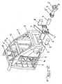
- the railway cab vehicle shown more particularly, by way of example, in Figure 1 of the accompanying drawings, comprises a energy-absorbing metal structure, which consists of zones 1 and 2 of dynamic plastic deformation, made up of fixed energy absorbing elements or interchangeable, provided respectively at the front ends and traffic of said vehicle.
- the deformation zones 1 and 2 dynamic plastic present means with mechanical resistance property different resulting in progressive deformation phases from the end vehicle correspondent.
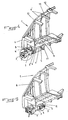
- the means with properties of mechanical resistance different from zone 1 of dynamic plastic deformation, provided at the front end of the vehicle are constituted by an automatic coupling 3 rigidly linked to a box 4 arranged in a frame element 5, formed in a non-deformable end portion 6 of the vehicle body, by a first energy absorbing element 7 inserted in the box 4 and pressing against the rear end of the automatic coupling 3, by at at least one second energy absorbing element 8 connecting the front part of the box 4 to the front face of the non-deformable end portion 6 of the vehicle body and by at least one series of elements 9 and 9 ′ with programmed plastic deformation, provided between the non-deformable end portion 6 of the vehicle body and the body of the vehicle itself.
- the automatic coupling 3 is constituted by a coupling head 3 'and by a body connecting this head to a 3 "hitch support rigidly connected to the box 4 by through fusible bolts 10 ( Figures 2 and 4).
- the assembly thus produced keeps the automatic coupling 3 in the service position in a first energy absorption phase corresponding to a shock not exceeding a speed of the order of 7 km / h, corresponding to a load mechanical fuse bolts 10 below their breaking limit by shear, said automatic coupling 3 then realizing energy absorption without deformation (Figure 4).
- the first energy absorbing element 7, inserted in the box 4 and leaning against the rear end of the automatic coupling 3, is advantageously constituted by a piece of destructible composite material under shape of a tube connected by its front end to the 3 "hitch support of the hitch automatic 3 and supported by its rear end on the bottom of the box 4, this bottom having at least one opening, not shown, for ejecting the material constituting the energy absorbing element 7, said opening having a section lower than that of the tube.
- the tube constituting the absorbing element of energy 7 is supported by an element of corresponding section at the bottom of the box 4, this support element having two material ejection openings constituting the energy absorbing element 7, diametrically opposite.
- the box 4 has a tubular rear part for receiving the body and hitch support 3 "of automatic hitch 3 and part flared front for receiving the head 3 ′ of said automatic coupling 3 provided lateral edges 4 'intended to cooperate with the second element or elements energy absorbers 8, the front face of these edges 4 'being provided with 4 "devices anti-overlap.
- These 4 "devices are of known type and allow, by form cooperation, to avoid mutual vertical displacement between two car ends.
- the frame member 5, formed in an end portion non-deformable 6, presents, on the one hand, at its end opposite to that receiving the box 4, an opening 11 intended to allow the ejection of the material constituting the energy absorbing element 7 during the crushing of the latter and, on the other hand, a length at least equal to that of the tubular rear part of the box 4 ( Figures 4 to 7).
- the second energy absorbing elements 8 connecting the front part of the box 4 on the front face of the non-deformable end part 6 of the body of the vehicle are in the form of deformable beams bolted to their ends, respectively on the front of the non-deformable end portion 6 of the body of the vehicle and on the rear face of the edges 4 ′ of the box 4, these beams deformable, each consisting of an assembly of deformation plates predetermined.
- Deformable structures of this type are known in particular from FR-A-2 694 255.
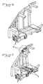
- These second energy absorbing elements 8 allow, like the shows Figure 6 of the accompanying drawings, a third phase of shock absorption by irreversible plastic deformation, for shock speeds up to 32 km / h.
- the constitution of the chassis element 5 allows, during the third energy absorption phase, complete retraction of the tubular rear part for receiving the body and the 3 "hitch support of the automatic hitch 3, box 4 with automatic coupling 3, in said chassis element 5.
- the front parts of the automatic coupling 3 and of the box 4 are then housed in the shield 6 'provided at the front end of the non-deformable end portion 6 of the vehicle body and thus completely eliminate the risk of tilting.
- the series or elements 9 and 9 'with plastic deformation programmed, provided between the non-deformable end part 6 of the body of the vehicle and the body of the vehicle itself are advantageously presented in the form of assemblies of sheets with progressive deformation from the front towards the rear of the vehicle ( Figures 3 and 7). These elements 9 and 9 'constitute the chassis extending between the non-deformable end portion 6 of the body of the vehicle and the body of the vehicle itself and are connected to roll bars rigid 12 of these.
- Elements 9 and 9 ' are preferably provided in pairs and are connected to an intermediate hoop 13 laterally defining a door opening and a technical room.
- the elements 9 and 9 'between two arches are limited to a limited number, so that their deformation can be carried out only by crushing, without generalized buckling.
- the driver's cab of the vehicle is provided with a survival tunnel 14 in the form of a trellis cage tubular, mounted between a pivot cross member 16 and the roof of the cabin and fixed on the rigid hoop 12 delimiting the body of the vehicle proper ( Figure 4).
- the elements 9' located between the intermediate arch 13 and the rigid arch 12 defining the body of the vehicle itself are arranged in such a way that their deformation progressive is carried out from the rear towards the front of the vehicle.
- These elements 9 and 9 ' are formed, as shown in Figure 3 annexed drawings, in the form of boxes, the lateral and central faces extending parallel to the longitudinal axis of the vehicle have material reliefs in the form of openings 15 or predeformations under form of ripples of matter.
- the openings 15 of the elements 9 and 9 ' have advantageously a decreasing section in the direction of the deformation and the undulations of elements 9 and 9 ′ have a decreasing amplitude in the same direction.
- the sheets forming the assemblies of sheets constituting the elements 9 and 9 ′ have a increasing thickness in the direction of deformation. So the resistance of elements 9 and 9 ' also increases during the deformation phase.
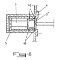
- Means with different mechanical strength properties than the rear zone 2 of dynamic plastic deformation, provided at the rear end of the vehicle are constituted, as shown in Figure 8 of the accompanying drawings, by a 3 "hitch support connected to an intermediate hitch body and cooperating with a box 4, housed in a chassis element 5 in the rear area 2 and fixed to said chassis, said hitch support 3 "resting in said box 4 on a energy absorbing element 7 and being connected to said box 4 by means of fuse bolts 10, the chassis 5 being further provided, at its end, with anti-overlapping devices not shown.
- the drawbar exerts on the support 3 "coupling force so that the fusible bolts 10 are sheared and the energy absorbing element 7 is crushed on the bottom of the box 4.
- the penetration of the drawbar 3 in the box 4 thus completely eliminates the risk of crutch and anti-overlapping devices, of known type, allow, by form cooperation, to avoid mutual vertical displacement between two car ends.
- a rail vehicle with driving cab comprising an energy absorbing structure, constituted by zones of dynamic plastic deformation, formed by absorbing elements fixed or interchangeable energy, allowing absorption of shock energy in progressive phases and ensuring maximum safety for the driver and The passengers.
Landscapes
- Engineering & Computer Science (AREA)
- Mechanical Engineering (AREA)
- Transportation (AREA)
- Chemical & Material Sciences (AREA)
- Combustion & Propulsion (AREA)
- Life Sciences & Earth Sciences (AREA)
- Wood Science & Technology (AREA)
- Vibration Dampers (AREA)
- Body Structure For Vehicles (AREA)
- Aiming, Guidance, Guns With A Light Source, Armor, Camouflage, And Targets (AREA)
Claims (17)
- Eisenbahnfahrzeug mit Fahrerkabine mit einer energieabsorbierenden Struktur, gebildet aus zwei Zonen (1 und 2) zur dynamischen, plastischen Deformation, gebildet aus festen oder austauschbaren energieabsorbierenden Elementen, jeweils vorgesehen an dem vorderen Ende und zwischen Fahrzeugen, wobei die Zonen (1 und 2) zur dynamische, plastischen Deformation Einrichtungen aufweisen, mit unterschiedlich mechanischen Widerstandseigenschaften, die progressive Deformationsphasen auslösen, ausgehend von dem korrespondierenden Ende des Fahrzeugs, dadurch gekennzeichnet, dass die Einrichtungen mit unterschiedlichen, mechanischen Widerstandseigenschaften der Zone (1) der dynamischen, plastischen Deformation, vorgesehen am vorderen Ende des Fahrzeugs, aus einer automatischen Kopplung (3) gebildet sind, die fest mit einem ersten Kasten (4) verbunden ist, angeordnet an einem Chassiselement (5), welches in einem nicht verformbaren Endbereich (6) des Fahrzeuggehäuses ausgebildet ist, durch ein erstes energieabsorbierendes Element (7), das in den Kasten (4) eingeführt ist und sich gegen das hintere Ende der automatischen Kopplung (3) abstützt, durch zumindest ein zweites energieabsorbierendes Element (8), das den vorderen Teil des Kastens (4) mit der Vorderseite des nicht deformierbaren Endbereichs (6) des Fahrzeuggehäuses verbindet und durch zumindest eine Reihe von Elementen (9 und 9') zur programmierten plastischen Deformation, vorgesehen zwischen dem nicht deformierbaren Endbereich (6) des Fahrzeuggehäuses und dem eigentlichen Fahrzeuggehäuse.
- Eisenbahnfahrzeug gemäß Anspruch 1, dadurch gekennzeichnet, dass die automatische Kopplung (3) durch einen Kopplungskopf (3') und durch einen Korpus gebildet ist, der den Kopf mit einer Kopplungshalterung (3'') verbindet, welche fest mit dem Kasten (4) mittels schmelzbarer Bolzen (10) verbunden ist.
- Eisenbahnfahrzeug nach einem der Ansprüche 1 und 2, dadurch gekennzeichnet, dass das erste energieabsorbierende Element (7), eingeführt in den Kasten (4) und abgestützt gegen das hintere Ende der automatischen Kopplung (3), durch ein Teil aus einem zerstörbaren Kompositmaterial in der Form einer Röhre gebildet wird, die an ihrem vorderen Ende mit der Kopplungshalterung (3") der automatischen Kopplung (3) verbunden ist und sich am hinteren Ende am Boden des Kastens (4) abstützt, wobei der Boden zumindest eine Ausstoßöffnung für das Material aufweist, welche das energieabsorbierende Element (7) bildet, wobei die Öffnung einen Querschnitt hat, der kleiner ist als derjenige der Röhre.
- Eisenbahnfahrzeug nach Anspruch 3, dadurch gekennzeichnet, dass die Röhre, die das energieabsorbierende Element (7) bildet, sich an einem Element abstützt, dessen Querschnitt demjenigen des Bodens des Kastens entspricht, wobei das Abstützelement (2) Ausstoßöffnungen für das Material aufweist, das das energieabsorbierende Element (7) bildet, die sich diametral gegenüberliegen.
- Eisenbahnfahrzeug nach einem der Ansprüche 1 bis 4, dadurch gekennzeichnet, dass der Kasten (4) einen hinteren röhrenförmigen Teil zur Aufnahme des Korpus der Kopplungshalterung (3") der automatischen Kopplung (3) aufweist und einen vorhergehenden aufgeweiteten Teil zur Aufnahme des Kopfes (3`) der automatischen Kopplung (3) versehen mit Seitenrändern (4') bestimmt für ein Zusammenwirken mit dem oder den zweiten energieabsorbierenden Elementen (8), wobei die Vorderseite der Ränder (4') mit Einrichtungen (4") zum Schutz gegen Versatz versehen ist.
- Eisenbahnfahrzeug nach einem der Ansprüche 1 bis 5, dadurch gekennzeichnet, dass das Chassiselement (5), das in einem nicht deformierbaren Endbereich (6) ausgebildet ist, einerseits an seinem Ende, das demjenigen gegenüberliegt, welches den Kasten (4) aufnimmt, eine Öffnung (11) aufweist, die für einen Ausstoß des Materials vorgesehen ist, welches das energieabsorbierende Element (7) bildet, während des Stauchens des letzteren und, andererseits, eine Länge, die zumindest gleich derjenigen des hinteren röhrenförmigen Teils des Kastens (4) ist.
- Eisenbahnfahrzeug nach einem der Ansprüche 1 bis 3, 5 und 6, dadurch gekennzeichnet, dass der oder die zweiten energieabsorbierenden Elemente (8), die den vorderen Teil des Kastens (4) mit der Vorderseite des nicht deformierbaren Teils (6) des Fahrzeuggehäuses verbinden, sich in der Form von deformierbaren Trägern zeigen, die an ihren Enden verbolzt sind, jeweils vorne mit dem nicht deformierbaren Teil (6) des Fahrzeuggehäuses und an der Rückseite mit den Rändern (4') des Kastens (4), wobei die verformbaren Träger jeweils aus einer Anordnung von Blechen mit vorbestimmter Deformation gebildet sind.
- Eisenbahnfahrzeug nach Anspruch 1, dadurch gekennzeichnet, dass das oder die Reihe von Elementen (9 und 9') mit programmierter plastischer Deformation, vorgesehen zwischen dem nicht deformierbaren Teil (6) des Fahrzeuggehäuses und dem eigentlichen Fahrzeuggehäuse sich in der Form einer Anordnung von Blechen mit progressiver Deformation zeigt, ausgehend von der Vorderseite zur Rückseite des Fahrzeugs.
- Eisenbahnfahrzeug nach Anspruch 8, dadurch gekennzeichnet, dass die Elemente (9 und 9') zur programmierten plastischen Deformation, die das Chassis bilden, sich zwischen dem nicht deformierbaren Teil (6) des Fahrzeuggehäuses und dem eigentlichen Fahrzeuggehäuse erstrecken und über steife Bögen (12) mit den letzteren verbunden sind.
- Eisenbahnfahrzeug nach einem der Ansprüche 8 und 9, dadurch gekennzeichnet, dass die Elemente (9 und 9') zur programmierten plastischen Deformation paarweise vorgesehen sind und über einen Zwischenbogen (13) verbunden sind, der seitlich eine Türöffnung und einen Technikraum begrenzt.
- Eisenbahnfahrzeug nach einem der Ansprüche 1 und 8, dadurch gekennzeichnet, dass die Fahrerkabine mit einem Überlebenstunnel (14) in der Form eines Röhrennetzkäfigs versehen ist, der zwischen einer Schwenktraverse (16) und dem Kabinendach montiert ist und an dem steifen Bogen (12) zur Begrenzung des eigentlichen Fahrzeuggehäuses fixiert ist.
- Eisenbahnfahrzeug nach Anspruch 10, dadurch gekennzeichnet, dass die Elemente (9') zur programmierten plastischen Deformation, die zwischen dem Zwischenbogen (13) und dem steifen Bogen (12), der das eigentliche Fahrzeuggehäuse begrenzt, so angeordnet sind, dass ihre progressive Deformation von der Rückseite zur Vorderseite des Fahrzeugs erfolgt.
- Eisenbahnfahrzeug nach einem der Ansprüche 1 und 8 bis 12, dadurch gekennzeichnet, dass die Elemente (9 und 9') zur programmierten plastischen Deformation in der Form von Kästen vorgesehen sind, wobei die seitlichen und zentralen Seiten, die sich parallel zur Längsachse des Fahrzeugs erstrecken, Ausnehmungen des Materials in der Form von Öffnungen (15) oder Vorverformungen in der Form von Wellungen des Materials aufweisen.
- Eisenbahnfahrzeug nach Anspruch 13, dadurch gekennzeichnet, dass die Öffnungen (15) der Elemente (9 und 9') zur programmierten plastischen Deformation vorteilhafterweise einen in Richtung der Deformation abnehmende Querschnitt und die Wellungen eine in die selbe Richtung abnehmende Amplitude aufweisen.
- Eisenbahnfahrzeug nach einem der Ansprüche 1 und 8 bis 14, dadurch gekennzeichnet, dass die Bleche, die die Anordnung der Bleche zur Bildung der Elemente (9 und 9') zur programmierten plastischen Deformation bilden, eine Dicke aufweisen, die in Richtung der Deformation zunimmt.
- Eisenbahnfahrzeug nach einem der Ansprüche 1 bis 7, dadurch gekennzeichnet, dass die Einrichtungen mit unterschiedlichen mechanischen Widerstandseigenschaften der hinteren Zone (2) zur dynamischen, plastischen Deformation, vorgesehen am hinteren Ende des Fahrzeugs, durch eine Kopplungshalterung (3") gebildet werden, die mit einem Zwischenkorpus des Kopplungsglieds verbunden ist und mit einem Kasten (4) zusammenwirkt, angeordnet in einem Chassiselement (5) der hinteren Zone (2) und fixiert an dem Chassis, wobei die Kopplungshalterung (3'') sich abstützt in dem Kasten (4) an einem Energieabsorptionselement (7) und mit dem Kasten (4) mittels Schmelzbolzen (10) verbunden ist, wobei das Chassis (5) andererseits an seinem Ende mit Einrichtungen zum Schutz gegen Versatz versehen ist.
- Eisenbahnfahrzeug nach einem der Ansprüche 1, 3 bis 7 und 16, dadurch gekennzeichnet, dass die energieabsorbierenden Elemente (7 und 8) in der Form von austauschbaren Elementen realisiert sind, die im Falle von zerstörerischen Stößen leicht ersetzt werden können.
Applications Claiming Priority (2)
| Application Number | Priority Date | Filing Date | Title |
|---|---|---|---|
| FR9605203A FR2747633B1 (fr) | 1996-04-19 | 1996-04-19 | Vehicule ferroviaire a cabine de conduite comportant une structure absorbeuse d'energie a deformation progressive |
| FR9605203 | 1996-04-19 |
Publications (2)
| Publication Number | Publication Date |
|---|---|
| EP0802100A1 EP0802100A1 (de) | 1997-10-22 |
| EP0802100B1 true EP0802100B1 (de) | 2001-09-12 |
Family
ID=9491569
Family Applications (1)
| Application Number | Title | Priority Date | Filing Date |
|---|---|---|---|
| EP97440039A Expired - Lifetime EP0802100B1 (de) | 1996-04-19 | 1997-04-18 | Schienenfahrzeug mit einem Fahrerstand, der eine energieaufnehmende Struktur mit progressiver Verformung aufweist |
Country Status (7)
| Country | Link |
|---|---|
| EP (1) | EP0802100B1 (de) |
| AT (1) | ATE205448T1 (de) |
| DE (1) | DE69706597T2 (de) |
| DK (1) | DK0802100T3 (de) |
| ES (1) | ES2161423T3 (de) |
| FR (1) | FR2747633B1 (de) |
| PT (1) | PT802100E (de) |
Cited By (2)
| Publication number | Priority date | Publication date | Assignee | Title |
|---|---|---|---|---|
| RU2231462C2 (ru) * | 2000-12-18 | 2004-06-27 | Альстом | Рельсовое транспортное средство, имеющее кабину машиниста, обеспеченную энергопоглощающей конструкцией, выполненной с возможностью воспринимать столкновение, происходящее выше рамы транспортного средства |
| DE102006002036A1 (de) * | 2006-01-16 | 2007-07-26 | Siemens Ag | Verfahren zum Einbauen eines Geräteschrankes in den Fahrerraum eines Schienenfahrzeuges |
Families Citing this family (77)
| Publication number | Priority date | Publication date | Assignee | Title |
|---|---|---|---|---|
| FR2765543B1 (fr) | 1997-07-02 | 2005-01-07 | Alstom Ddf | Vehicule ferroviaire comportant au moins un module d'extremite interchangeable |
| DE19817860A1 (de) * | 1998-04-22 | 1999-11-04 | Dwa Deutsche Waggonbau Gmbh | Sicherheitseinrichtung für Fahrzeugführer von Schienenfahrzeugen |
| DE19817861C2 (de) * | 1998-04-22 | 2001-09-06 | Dwa Deutsche Waggonbau Gmbh | Kollisionsschutzeinrichtung für Schienenfahrzeuge |
| FR2785028B1 (fr) | 1998-10-23 | 2000-12-15 | Dytesys | Dispositif amortisseur de chocs |
| EP1090829B1 (de) * | 1999-10-06 | 2003-04-23 | Alcan Technology & Management AG | Anordnung zur Absorption von Aufprallenergie |
| DE19956856A1 (de) * | 1999-11-25 | 2001-05-31 | Siemens Duewag Gmbh | Schienenfahrzeug zur Personenbeförderung, insbesondere für den Nahverkehr |
| CA2387344C (en) * | 2000-08-28 | 2006-11-28 | Mitsubishi Heavy Industries, Ltd. | Vehicle body structure |
| DE10152986A1 (de) * | 2001-10-26 | 2003-05-08 | Siemens Ag | Kletterschutzvorrichtung für Schienenfahrzeuge mit Seitenpuffern |
| DE10155257B4 (de) * | 2001-11-09 | 2008-02-21 | Alstom Lhb Gmbh | Kollisionsschutzeinrichtung für Schienenfahrzeuge |
| JP3848227B2 (ja) | 2002-09-02 | 2006-11-22 | 株式会社日立製作所 | 軌条車両 |
| JP4912559B2 (ja) * | 2002-09-11 | 2012-04-11 | 株式会社日立製作所 | 軌条車両 |
| DE10301273A1 (de) * | 2003-01-15 | 2004-04-22 | Siemens Ag | Vorrichtung zum Umwandeln kinetischer Energie bei einem Aufprall eines Schienenfahrzeuges |
| DE10321238B4 (de) * | 2003-05-12 | 2014-08-07 | Siemens Aktiengesellschaft | Schienenfahrzeug mit Bugspitze |
| WO2005028275A1 (en) * | 2003-09-19 | 2005-03-31 | Siemens Transportation Systems, Inc. | Integrated impact protecting system |
| DE102004003142A1 (de) * | 2004-01-21 | 2005-08-18 | Siemens Ag | Schienenfahrzeug mit einem Wagenkastenvorbau |
| GB2411632A (en) | 2004-03-01 | 2005-09-07 | Bombardier Transp Gmbh | Rail vehicle cabin with yieldable parts |
| GB2411633A (en) * | 2004-03-01 | 2005-09-07 | Bombardier Transp Gmbh | Railway vehicle with cabin having a collapsible front section |
| DE102004028964A1 (de) | 2004-05-07 | 2005-12-01 | Siemens Ag | Fahrzeug mit Deformationszone |
| DE202005004885U1 (de) | 2005-03-26 | 2006-08-03 | Alstom Lhb Gmbh | Fußbodenausbildung mit Fußbodenplatte im Fahrzeugführerraum von Schienenfahrzeugen |
| JP4912614B2 (ja) * | 2005-05-09 | 2012-04-11 | 株式会社日立製作所 | 軌条車両 |
| EP1873037B1 (de) * | 2006-05-10 | 2011-12-28 | Hitachi, Ltd. | Vorrichtung zur Absorption von Kollisionsenergie und Schienenfahrzeug mit der Vorrichtung |
| JP4712604B2 (ja) * | 2006-05-10 | 2011-06-29 | 株式会社日立製作所 | 輸送機器 |
| JP5179053B2 (ja) * | 2006-05-10 | 2013-04-10 | 株式会社日立製作所 | 衝突エネルギー吸収装置及びそれを備えた軌条車両 |
| KR100797046B1 (ko) | 2006-09-05 | 2008-01-22 | 한국철도기술연구원 | 슬라이딩 방식 전두부 충격에너지 흡수장치 |
| DE102006043926A1 (de) * | 2006-09-14 | 2008-03-27 | Voith Turbo Lokomotivtechnik Gmbh & Co. Kg | Lokomotive |
| DE102006044397A1 (de) * | 2006-09-18 | 2008-03-27 | Bombardier Transportation Gmbh | Kopfmodul für ein Schienenfahrzeug |
| JP4845688B2 (ja) * | 2006-11-21 | 2011-12-28 | 株式会社日立製作所 | 車両 |
| ITTO20060863A1 (it) | 2006-12-04 | 2008-06-05 | Ansaldobreda Spa | Carrozza di testa di un treno provvista di una struttura frontale che assorbe energia in caso di collisione |
| RU2334637C1 (ru) * | 2007-05-03 | 2008-09-27 | Открытое акционерное общество "РИФ" | Модуль кабины управления для транспортного средства, преимущественно для магистральных локомотивов |
| DE102008007590A1 (de) * | 2008-01-31 | 2009-08-06 | Siemens Aktiengesellschaft | Kopfbauteil zum Ausbilden der Stirnseite eines Fahrzeugs |
| JP2009241772A (ja) * | 2008-03-31 | 2009-10-22 | Hitachi Ltd | 軌条車両 |
| PL2130739T3 (pl) * | 2008-06-06 | 2014-02-28 | Bombardier Transp Gmbh | Zespół ostoi wagonu kolejowego i modułowy korpus wagonu dla pojazdu szynowego |
| WO2010029188A1 (de) | 2008-09-15 | 2010-03-18 | Voith Patent Gmbh | Fahrzeugkopf zur befestigung an der stirnseite eines spurgebundenen fahrzeuges, insbesondere eines schienenfahrzeuges |
| EP2295305B2 (de) | 2009-09-15 | 2017-06-07 | Voith Patent GmbH | Energieverzehrvorrichtung, insbesondere in Gestalt einer Stoßsicherung für ein spurgeführtes Fahrzeug |
| JP5161251B2 (ja) * | 2010-03-25 | 2013-03-13 | 株式会社日立製作所 | 衝撃吸収構造を備える鉄道車両 |
| JP5209666B2 (ja) * | 2010-05-10 | 2013-06-12 | 日本車輌製造株式会社 | 鉄道車両 |
| CN101817350B (zh) * | 2010-05-10 | 2011-12-21 | 南车株洲电力机车有限公司 | 一种司机室 |
| US9090266B2 (en) | 2010-05-10 | 2015-07-28 | Nippon Sharyo, Ltd. | Railway vehicle |
| CN102180182A (zh) * | 2011-03-30 | 2011-09-14 | 中南大学 | 一种带切削式吸能防撞器的车钩缓冲装置 |
| ES2487991B1 (es) * | 2011-11-30 | 2015-06-02 | Patentes Talgo, S.L. | Sistema de absorción de energía para coches cabina de vehículos ferroviarios |
| US9248846B2 (en) * | 2011-12-02 | 2016-02-02 | Nippon Sharyo, Ltd. | Rolling stock |
| US9421989B2 (en) | 2012-01-27 | 2016-08-23 | Nippon Sharyo, Ltd. | Rolling stock |
| CN102975731B (zh) * | 2012-04-24 | 2015-08-12 | 南车南京浦镇车辆有限公司 | 轨道车辆司机室骨架与车体的安装结构 |
| DE102012212967A1 (de) * | 2012-07-24 | 2014-01-30 | Siemens Aktiengesellschaft | Zugkopfteil |
| CN103101553B (zh) * | 2013-03-06 | 2015-04-22 | 南车南京浦镇车辆有限公司 | 带防爬吸能装置的列车前端组成 |
| CN103192845B (zh) * | 2013-04-22 | 2015-09-30 | 西南交通大学 | 一种防爬防偏吸能装置 |
| AT514375B1 (de) | 2013-06-04 | 2015-02-15 | Siemens Ag Oesterreich | Schienenfahrzeug mit Verformungszone |
| CN104442857B (zh) * | 2013-09-22 | 2017-10-03 | 中车青岛四方机车车辆股份有限公司 | 一种轨道车辆司机室吸能结构 |
| CN103625500B (zh) * | 2013-10-10 | 2016-09-07 | 中车青岛四方机车车辆股份有限公司 | 轨道车辆底架端部防撞结构 |
| CN103625501B (zh) * | 2013-10-17 | 2016-06-22 | 中车青岛四方机车车辆股份有限公司 | 一种轨道车辆防爬缓冲结构 |
| CN103625502B (zh) * | 2013-10-18 | 2016-05-25 | 中车青岛四方机车车辆股份有限公司 | 一种轨道车辆前端吸能装置 |
| CN103770798A (zh) * | 2014-02-11 | 2014-05-07 | 唐山轨道客车有限责任公司 | 列车前端结构及列车 |
| CN104787073A (zh) * | 2015-03-26 | 2015-07-22 | 长春轨道客车股份有限公司 | 高速动车组头车底架端部结构 |
| CN104943702B (zh) * | 2015-06-30 | 2018-08-03 | 中车青岛四方机车车辆股份有限公司 | 一种隔墙及具有该隔墙的轨道车辆 |
| US11021176B2 (en) | 2015-09-30 | 2021-06-01 | Crrc Qingdao Sifang Co., Ltd. | Energy absorption device and rail vehicle having same |
| CN105151075B (zh) * | 2015-09-30 | 2018-03-20 | 中车青岛四方机车车辆股份有限公司 | 一种吸能装置及具有该吸能装置的轨道车辆 |
| CN105292164B (zh) * | 2015-10-16 | 2017-11-14 | 中南大学 | 伸缩式轨道车辆碰撞吸能装置 |
| GB201522419D0 (en) * | 2015-12-18 | 2016-02-03 | Hitachi Ltd | Railway vehicle provided with collision energy absorption structure |
| CN105818831B (zh) * | 2016-03-31 | 2017-10-24 | 中南大学 | 组合式吸能机构及具有该组合式吸能机构的轨道车辆 |
| CN105946890A (zh) * | 2016-06-20 | 2016-09-21 | 中车唐山机车车辆有限公司 | 吸能装置及轨道车辆 |
| CN106240587B (zh) * | 2016-08-30 | 2018-12-14 | 中车株洲电力机车有限公司 | 一种轨道车辆车头结构 |
| CN106364520B (zh) * | 2016-09-28 | 2018-04-13 | 中南大学 | 一种列车碰撞防护方法及系统 |
| CN106240595B (zh) * | 2016-09-28 | 2018-02-23 | 中南大学 | 一种轨道车辆用碰撞吸能装置 |
| CN106347387B (zh) * | 2016-10-09 | 2019-02-26 | 中车株洲电力机车有限公司 | 一种轨道车辆头车结构 |
| CN106672010A (zh) * | 2016-11-22 | 2017-05-17 | 中车长春轨道客车股份有限公司 | 一种动车组头车被动安全防护装置 |
| WO2018112684A1 (zh) * | 2016-12-19 | 2018-06-28 | 中车株洲电力机车有限公司 | 一种轨道车辆车头结构 |
| CN107200034A (zh) * | 2017-05-23 | 2017-09-26 | 中车唐山机车车辆有限公司 | 吸能组件及动车 |
| CN108482414B (zh) * | 2018-03-26 | 2019-06-11 | 中车株洲电力机车有限公司 | 轨道车辆及其轨道车辆牵缓结构 |
| JP7218060B2 (ja) * | 2019-03-29 | 2023-02-06 | 日本車輌製造株式会社 | 鉄道車両 |
| CN110920650B (zh) * | 2019-09-18 | 2021-04-16 | 中车南京浦镇车辆有限公司 | 一种轨道车辆底架前端防撞结构 |
| CN112977518B (zh) * | 2019-12-13 | 2023-02-28 | 中车唐山机车车辆有限公司 | 一种轨道车辆及其车体和端底架 |
| CN111605568A (zh) * | 2020-07-03 | 2020-09-01 | 中车戚墅堰机车有限公司 | 一种具有多级碰撞保护的内燃机车司机室 |
| CN112078618B (zh) * | 2020-09-16 | 2022-01-18 | 中车株洲电力机车有限公司 | 一种轨道车辆底架结构 |
| CN112109764B (zh) * | 2020-09-16 | 2021-09-17 | 中车株洲电力机车有限公司 | 一种挡车器及轨道车辆防撞方法 |
| CN112109758B (zh) * | 2020-09-16 | 2021-10-26 | 中车株洲电力机车有限公司 | 一种轨道车辆防撞系统及防撞方法 |
| CN112078620B (zh) * | 2020-09-16 | 2021-09-17 | 中车株洲电力机车有限公司 | 一种轨道车辆前端结构 |
| CN112389488B (zh) * | 2020-11-02 | 2022-05-17 | 中车唐山机车车辆有限公司 | 一种轨道车辆及其司机室车 |
Family Cites Families (3)
| Publication number | Priority date | Publication date | Assignee | Title |
|---|---|---|---|---|
| DE635018C (de) * | 1933-01-14 | 1936-09-14 | Curt Stedefeld Dipl Ing | Stromlinienfoermiger Kopfteil mit zurueckliegendem Fuehrerstandsaufbau fuer Triebwagen mit hohen Geschwindigkeiten |
| GB2257770A (en) * | 1991-07-16 | 1993-01-20 | Fischer Georg Formtech | Shock absorber for a coupling |
| FR2712950B1 (fr) * | 1993-11-25 | 1995-12-29 | Gec Alsthom Transport Sa | Dispositifs et procédé d'amortissement de choc, ossature et véhicule comportant de tels dispositifs d'amortissement de choc. |
-
1996
- 1996-04-19 FR FR9605203A patent/FR2747633B1/fr not_active Expired - Fee Related
-
1997
- 1997-04-18 ES ES97440039T patent/ES2161423T3/es not_active Expired - Lifetime
- 1997-04-18 DK DK97440039T patent/DK0802100T3/da active
- 1997-04-18 AT AT97440039T patent/ATE205448T1/de not_active IP Right Cessation
- 1997-04-18 EP EP97440039A patent/EP0802100B1/de not_active Expired - Lifetime
- 1997-04-18 PT PT97440039T patent/PT802100E/pt unknown
- 1997-04-18 DE DE69706597T patent/DE69706597T2/de not_active Expired - Fee Related
Cited By (3)
| Publication number | Priority date | Publication date | Assignee | Title |
|---|---|---|---|---|
| RU2231462C2 (ru) * | 2000-12-18 | 2004-06-27 | Альстом | Рельсовое транспортное средство, имеющее кабину машиниста, обеспеченную энергопоглощающей конструкцией, выполненной с возможностью воспринимать столкновение, происходящее выше рамы транспортного средства |
| DE102006002036A1 (de) * | 2006-01-16 | 2007-07-26 | Siemens Ag | Verfahren zum Einbauen eines Geräteschrankes in den Fahrerraum eines Schienenfahrzeuges |
| DE102006002036B4 (de) * | 2006-01-16 | 2014-07-17 | Siemens Aktiengesellschaft | Verfahren zum Einbauen eines Geräteschrankes in den Fahrerraum eines Schienenfahrzeuges |
Also Published As
| Publication number | Publication date |
|---|---|
| PT802100E (pt) | 2002-01-30 |
| ATE205448T1 (de) | 2001-09-15 |
| FR2747633B1 (fr) | 2003-01-31 |
| EP0802100A1 (de) | 1997-10-22 |
| DK0802100T3 (da) | 2001-12-17 |
| DE69706597D1 (de) | 2001-10-18 |
| ES2161423T3 (es) | 2001-12-01 |
| FR2747633A1 (fr) | 1997-10-24 |
| DE69706597T2 (de) | 2002-07-11 |
Similar Documents
| Publication | Publication Date | Title |
|---|---|---|
| EP0802100B1 (de) | Schienenfahrzeug mit einem Fahrerstand, der eine energieaufnehmende Struktur mit progressiver Verformung aufweist | |
| CA2121995C (fr) | Dispositif d'amortissement de choc | |
| EP0655565B1 (de) | Stossdämpfende Vorrichtungen und Methode, Gerippe und Fahrzeug die diese stossdämpfende Vorrichtungen aufweisen | |
| CA2364957C (fr) | Vehicule ferroviaire a cabine de conduite comportant une structure absorbeuse d'energie adaptee a une collision au-dessus du chassis du vehicule | |
| EP1893469B1 (de) | Geführter unterbereich der front eines automobils | |
| EP1942033B1 (de) | Auflagerteil für Stoßdämpfersystem, das für die Montage am Ende eines Längsträgers eines Kraftfahrzeugs bestimmt ist | |
| FR2698840A1 (fr) | Véhicule ferroviaire à cabine de conduite comportant une structure absorbeuse d'énergie. | |
| EP1426242A2 (de) | Schalenförmiger Stossfängerträger mit einer Zweitschale und einem Verstärkungselement | |
| EP2934953B1 (de) | Stossdämpfungsvorrichtung für die vorder- oder hinterstruktur eines fahrzeugs | |
| EP0581707B1 (de) | Struktur zur Energieaufnahme, insbesondere für Eisenbahnfahrzeuge | |
| EP1827943B1 (de) | Stossdämpfungsvorrichtung für eisenbahnfahrzeug | |
| EP3554923A1 (de) | Unterbodenstruktur eines kraftfahrzeugs, insbesondere eines hybridkraftfahrzeugs, die für einen seitlichen stoss ausgelegt ist | |
| FR3092067A1 (fr) | Berceau moteur pour véhicule automobile et véhicule comportant un tel berceau | |
| EP3059137B1 (de) | Dämpfungseinrichtung für die kupplungseinrichtung eines eisenbahnfahrzeugs | |
| EP1106467A1 (de) | Vorrichtung zur kontrollierten Verformung durch Krafteinwirkung oder zur Aufnahme von Energie durch Verformung, insbesondere Hindernisabweiser für ein Schienenfahrzeug | |
| FR3041580A1 (fr) | Structure de vehicule comportant un dispositif de renfort et vehicule comportant une telle structure | |
| EP1660364B1 (de) | Kraftfahrzeugvorderteilkonstruktion | |
| FR3022603B1 (fr) | Dispositif absorbeur d'energie et vehicule correspondant | |
| FR2810940A1 (fr) | Bloc avant comprenant des elements d'absorption d'energie de choc et vehicule automobile correspondant | |
| FR3081423A1 (fr) | Vehicule avec dispositif d’absorption a surface d’impact augmentant durant un choc. | |
| EP4001060B1 (de) | Frontstruktur eines kraftfahrzeugs mit frontalaufprallsteuerung mit geringer abdeckung | |
| CA2466204C (fr) | Procede d'amortissement de choc et ossature | |
| EP3424757B1 (de) | Hinterachse eines kraftfahrzeugs, die energieabsorptionsmittel eines seitlichen aufpralls umfasst | |
| FR2742776A1 (fr) | Elements de protection absorbant les chocs | |
| EP0669483A1 (de) | Energieaufnahmevorrichtung für Schienenfahrzeug |
Legal Events
| Date | Code | Title | Description |
|---|---|---|---|
| PUAI | Public reference made under article 153(3) epc to a published international application that has entered the european phase |
Free format text: ORIGINAL CODE: 0009012 |
|
| AK | Designated contracting states |
Kind code of ref document: A1 Designated state(s): AT BE CH DE DK ES GB IT LI NL PT SE |
|
| 17P | Request for examination filed |
Effective date: 19980313 |
|
| RAP1 | Party data changed (applicant data changed or rights of an application transferred) |
Owner name: ALSTOM DDF |
|
| 17Q | First examination report despatched |
Effective date: 19991223 |
|
| GRAG | Despatch of communication of intention to grant |
Free format text: ORIGINAL CODE: EPIDOS AGRA |
|
| GRAH | Despatch of communication of intention to grant a patent |
Free format text: ORIGINAL CODE: EPIDOS IGRA |
|
| GRAH | Despatch of communication of intention to grant a patent |
Free format text: ORIGINAL CODE: EPIDOS IGRA |
|
| GRAA | (expected) grant |
Free format text: ORIGINAL CODE: 0009210 |
|
| AK | Designated contracting states |
Kind code of ref document: B1 Designated state(s): AT BE CH DE DK ES GB IT LI NL PT SE |
|
| REF | Corresponds to: |
Ref document number: 205448 Country of ref document: AT Date of ref document: 20010915 Kind code of ref document: T |
|
| REG | Reference to a national code |
Ref country code: CH Ref legal event code: EP |
|
| GBT | Gb: translation of ep patent filed (gb section 77(6)(a)/1977) |
Effective date: 20010912 |
|
| REG | Reference to a national code |
Ref country code: CH Ref legal event code: NV Representative=s name: CABINET ROLAND NITHARDT CONSEILS EN PROPRIETE INDU |
|
| REF | Corresponds to: |
Ref document number: 69706597 Country of ref document: DE Date of ref document: 20011018 |
|
| REG | Reference to a national code |
Ref country code: ES Ref legal event code: FG2A Ref document number: 2161423 Country of ref document: ES Kind code of ref document: T3 |
|
| REG | Reference to a national code |
Ref country code: GB Ref legal event code: IF02 |
|
| REG | Reference to a national code |
Ref country code: PT Ref legal event code: SC4A Free format text: AVAILABILITY OF NATIONAL TRANSLATION Effective date: 20011031 |
|
| PLBE | No opposition filed within time limit |
Free format text: ORIGINAL CODE: 0009261 |
|
| STAA | Information on the status of an ep patent application or granted ep patent |
Free format text: STATUS: NO OPPOSITION FILED WITHIN TIME LIMIT |
|
| 26N | No opposition filed | ||
| PGFP | Annual fee paid to national office [announced via postgrant information from national office to epo] |
Ref country code: PT Payment date: 20090331 Year of fee payment: 13 |
|
| PGFP | Annual fee paid to national office [announced via postgrant information from national office to epo] |
Ref country code: ES Payment date: 20090422 Year of fee payment: 13 Ref country code: DK Payment date: 20090415 Year of fee payment: 13 |
|
| PGFP | Annual fee paid to national office [announced via postgrant information from national office to epo] |
Ref country code: SE Payment date: 20090416 Year of fee payment: 13 Ref country code: NL Payment date: 20090415 Year of fee payment: 13 Ref country code: IT Payment date: 20090428 Year of fee payment: 13 Ref country code: DE Payment date: 20090422 Year of fee payment: 13 Ref country code: AT Payment date: 20090416 Year of fee payment: 13 |
|
| PGFP | Annual fee paid to national office [announced via postgrant information from national office to epo] |
Ref country code: BE Payment date: 20090528 Year of fee payment: 13 |
|
| PGFP | Annual fee paid to national office [announced via postgrant information from national office to epo] |
Ref country code: CH Payment date: 20090417 Year of fee payment: 13 |
|
| PGFP | Annual fee paid to national office [announced via postgrant information from national office to epo] |
Ref country code: GB Payment date: 20090421 Year of fee payment: 13 |
|
| BERE | Be: lapsed |
Owner name: *ALSTOM DDF Effective date: 20100430 |
|
| REG | Reference to a national code |
Ref country code: NL Ref legal event code: V1 Effective date: 20101101 |
|
| EUG | Se: european patent has lapsed | ||
| REG | Reference to a national code |
Ref country code: CH Ref legal event code: PL |
|
| REG | Reference to a national code |
Ref country code: DK Ref legal event code: EBP |
|
| GBPC | Gb: european patent ceased through non-payment of renewal fee |
Effective date: 20100418 |
|
| PG25 | Lapsed in a contracting state [announced via postgrant information from national office to epo] |
Ref country code: NL Free format text: LAPSE BECAUSE OF NON-PAYMENT OF DUE FEES Effective date: 20101101 Ref country code: AT Free format text: LAPSE BECAUSE OF NON-PAYMENT OF DUE FEES Effective date: 20100418 |
|
| PG25 | Lapsed in a contracting state [announced via postgrant information from national office to epo] |
Ref country code: PT Free format text: LAPSE BECAUSE OF NON-PAYMENT OF DUE FEES Effective date: 20101018 Ref country code: LI Free format text: LAPSE BECAUSE OF NON-PAYMENT OF DUE FEES Effective date: 20100430 Ref country code: DE Free format text: LAPSE BECAUSE OF NON-PAYMENT OF DUE FEES Effective date: 20101103 Ref country code: CH Free format text: LAPSE BECAUSE OF NON-PAYMENT OF DUE FEES Effective date: 20100430 |
|
| PG25 | Lapsed in a contracting state [announced via postgrant information from national office to epo] |
Ref country code: IT Free format text: LAPSE BECAUSE OF NON-PAYMENT OF DUE FEES Effective date: 20100418 Ref country code: GB Free format text: LAPSE BECAUSE OF NON-PAYMENT OF DUE FEES Effective date: 20100418 Ref country code: BE Free format text: LAPSE BECAUSE OF NON-PAYMENT OF DUE FEES Effective date: 20100430 |
|
| PG25 | Lapsed in a contracting state [announced via postgrant information from national office to epo] |
Ref country code: DK Free format text: LAPSE BECAUSE OF NON-PAYMENT OF DUE FEES Effective date: 20100503 |
|
| REG | Reference to a national code |
Ref country code: ES Ref legal event code: FD2A Effective date: 20110715 |
|
| PG25 | Lapsed in a contracting state [announced via postgrant information from national office to epo] |
Ref country code: ES Free format text: LAPSE BECAUSE OF NON-PAYMENT OF DUE FEES Effective date: 20110705 |
|
| PG25 | Lapsed in a contracting state [announced via postgrant information from national office to epo] |
Ref country code: ES Free format text: LAPSE BECAUSE OF NON-PAYMENT OF DUE FEES Effective date: 20100419 |
|
| PG25 | Lapsed in a contracting state [announced via postgrant information from national office to epo] |
Ref country code: SE Free format text: LAPSE BECAUSE OF NON-PAYMENT OF DUE FEES Effective date: 20100419 |