EP0802100B1 - Railway vehicle with a driverscompartment having an energy absorbing structure with progressive deformation - Google Patents
Railway vehicle with a driverscompartment having an energy absorbing structure with progressive deformation Download PDFInfo
- Publication number
- EP0802100B1 EP0802100B1 EP97440039A EP97440039A EP0802100B1 EP 0802100 B1 EP0802100 B1 EP 0802100B1 EP 97440039 A EP97440039 A EP 97440039A EP 97440039 A EP97440039 A EP 97440039A EP 0802100 B1 EP0802100 B1 EP 0802100B1
- Authority
- EP
- European Patent Office
- Prior art keywords
- box
- section
- energy
- members
- rail vehicle
- Prior art date
- Legal status (The legal status is an assumption and is not a legal conclusion. Google has not performed a legal analysis and makes no representation as to the accuracy of the status listed.)
- Expired - Lifetime
Links
Images

Classifications
-
- B—PERFORMING OPERATIONS; TRANSPORTING
- B62—LAND VEHICLES FOR TRAVELLING OTHERWISE THAN ON RAILS
- B62D—MOTOR VEHICLES; TRAILERS
- B62D21/00—Understructures, i.e. chassis frame on which a vehicle body may be mounted
- B62D21/15—Understructures, i.e. chassis frame on which a vehicle body may be mounted having impact absorbing means, e.g. a frame designed to permanently or temporarily change shape or dimension upon impact with another body
-
- B—PERFORMING OPERATIONS; TRANSPORTING
- B61—RAILWAYS
- B61D—BODY DETAILS OR KINDS OF RAILWAY VEHICLES
- B61D15/00—Other railway vehicles, e.g. scaffold cars; Adaptations of vehicles for use on railways
- B61D15/06—Buffer cars; Arrangements or construction of railway vehicles for protecting them in case of collisions
-
- B—PERFORMING OPERATIONS; TRANSPORTING
- B61—RAILWAYS
- B61D—BODY DETAILS OR KINDS OF RAILWAY VEHICLES
- B61D17/00—Construction details of vehicle bodies
- B61D17/04—Construction details of vehicle bodies with bodies of metal; with composite, e.g. metal and wood body structures
- B61D17/06—End walls
-
- B—PERFORMING OPERATIONS; TRANSPORTING
- B61—RAILWAYS
- B61F—RAIL VEHICLE SUSPENSIONS, e.g. UNDERFRAMES, BOGIES OR ARRANGEMENTS OF WHEEL AXLES; RAIL VEHICLES FOR USE ON TRACKS OF DIFFERENT WIDTH; PREVENTING DERAILING OF RAIL VEHICLES; WHEEL GUARDS, OBSTRUCTION REMOVERS OR THE LIKE FOR RAIL VEHICLES
- B61F1/00—Underframes
- B61F1/08—Details
- B61F1/10—End constructions
-
- B—PERFORMING OPERATIONS; TRANSPORTING
- B61—RAILWAYS
- B61F—RAIL VEHICLE SUSPENSIONS, e.g. UNDERFRAMES, BOGIES OR ARRANGEMENTS OF WHEEL AXLES; RAIL VEHICLES FOR USE ON TRACKS OF DIFFERENT WIDTH; PREVENTING DERAILING OF RAIL VEHICLES; WHEEL GUARDS, OBSTRUCTION REMOVERS OR THE LIKE FOR RAIL VEHICLES
- B61F19/00—Wheel guards; Bumpers; Obstruction removers or the like
- B61F19/04—Bumpers or like collision guards
-
- B—PERFORMING OPERATIONS; TRANSPORTING
- B61—RAILWAYS
- B61G—COUPLINGS; DRAUGHT AND BUFFING APPLIANCES
- B61G9/00—Draw-gear
- B61G9/04—Draw-gear combined with buffing appliances
Definitions
- the present invention relates to the field of construction metallic of vehicles, in particular railway with driving cab, and has for object such a vehicle comprising a deformation energy absorbing structure progressive.
- the purpose of such a structure is to protect passengers and the driver of the vehicle in the event of a collision.
- a vehicle has been proposed by FR-A-2 698 840 railway with driver's cab having an absorbent metallic structure of energy, consisting of zones of dynamic plastic deformation, formed fixed or interchangeable energy absorbing elements, provided at the ends of said vehicle.
- Such a structure allows energy absorption over a significant length by dynamic plastic deformation of zones predetermined, namely from the front of the driver's cab and at the level of the intercirculation couplings.
- a railway vehicle with a driving cabin comprising a energy absorbing structure is also known from EP-A-0 655 556, from the same Applicant.
- the object of the present invention is to overcome these drawbacks by proposing a railway vehicle with a driving cabin comprising a structure energy absorber with progressive deformation allowing to control the direction of progression of the deformation during an impact.
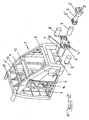
- the railway cab vehicle shown more particularly, by way of example, in Figure 1 of the accompanying drawings, comprises a energy-absorbing metal structure, which consists of zones 1 and 2 of dynamic plastic deformation, made up of fixed energy absorbing elements or interchangeable, provided respectively at the front ends and traffic of said vehicle.
- the deformation zones 1 and 2 dynamic plastic present means with mechanical resistance property different resulting in progressive deformation phases from the end vehicle correspondent.
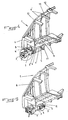
- the means with properties of mechanical resistance different from zone 1 of dynamic plastic deformation, provided at the front end of the vehicle are constituted by an automatic coupling 3 rigidly linked to a box 4 arranged in a frame element 5, formed in a non-deformable end portion 6 of the vehicle body, by a first energy absorbing element 7 inserted in the box 4 and pressing against the rear end of the automatic coupling 3, by at at least one second energy absorbing element 8 connecting the front part of the box 4 to the front face of the non-deformable end portion 6 of the vehicle body and by at least one series of elements 9 and 9 ′ with programmed plastic deformation, provided between the non-deformable end portion 6 of the vehicle body and the body of the vehicle itself.
- the automatic coupling 3 is constituted by a coupling head 3 'and by a body connecting this head to a 3 "hitch support rigidly connected to the box 4 by through fusible bolts 10 ( Figures 2 and 4).
- the assembly thus produced keeps the automatic coupling 3 in the service position in a first energy absorption phase corresponding to a shock not exceeding a speed of the order of 7 km / h, corresponding to a load mechanical fuse bolts 10 below their breaking limit by shear, said automatic coupling 3 then realizing energy absorption without deformation (Figure 4).
- the first energy absorbing element 7, inserted in the box 4 and leaning against the rear end of the automatic coupling 3, is advantageously constituted by a piece of destructible composite material under shape of a tube connected by its front end to the 3 "hitch support of the hitch automatic 3 and supported by its rear end on the bottom of the box 4, this bottom having at least one opening, not shown, for ejecting the material constituting the energy absorbing element 7, said opening having a section lower than that of the tube.
- the tube constituting the absorbing element of energy 7 is supported by an element of corresponding section at the bottom of the box 4, this support element having two material ejection openings constituting the energy absorbing element 7, diametrically opposite.
- the box 4 has a tubular rear part for receiving the body and hitch support 3 "of automatic hitch 3 and part flared front for receiving the head 3 ′ of said automatic coupling 3 provided lateral edges 4 'intended to cooperate with the second element or elements energy absorbers 8, the front face of these edges 4 'being provided with 4 "devices anti-overlap.
- These 4 "devices are of known type and allow, by form cooperation, to avoid mutual vertical displacement between two car ends.
- the frame member 5, formed in an end portion non-deformable 6, presents, on the one hand, at its end opposite to that receiving the box 4, an opening 11 intended to allow the ejection of the material constituting the energy absorbing element 7 during the crushing of the latter and, on the other hand, a length at least equal to that of the tubular rear part of the box 4 ( Figures 4 to 7).
- the second energy absorbing elements 8 connecting the front part of the box 4 on the front face of the non-deformable end part 6 of the body of the vehicle are in the form of deformable beams bolted to their ends, respectively on the front of the non-deformable end portion 6 of the body of the vehicle and on the rear face of the edges 4 ′ of the box 4, these beams deformable, each consisting of an assembly of deformation plates predetermined.
- Deformable structures of this type are known in particular from FR-A-2 694 255.
- These second energy absorbing elements 8 allow, like the shows Figure 6 of the accompanying drawings, a third phase of shock absorption by irreversible plastic deformation, for shock speeds up to 32 km / h.
- the constitution of the chassis element 5 allows, during the third energy absorption phase, complete retraction of the tubular rear part for receiving the body and the 3 "hitch support of the automatic hitch 3, box 4 with automatic coupling 3, in said chassis element 5.
- the front parts of the automatic coupling 3 and of the box 4 are then housed in the shield 6 'provided at the front end of the non-deformable end portion 6 of the vehicle body and thus completely eliminate the risk of tilting.
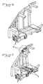
- the series or elements 9 and 9 'with plastic deformation programmed, provided between the non-deformable end part 6 of the body of the vehicle and the body of the vehicle itself are advantageously presented in the form of assemblies of sheets with progressive deformation from the front towards the rear of the vehicle ( Figures 3 and 7). These elements 9 and 9 'constitute the chassis extending between the non-deformable end portion 6 of the body of the vehicle and the body of the vehicle itself and are connected to roll bars rigid 12 of these.
- Elements 9 and 9 ' are preferably provided in pairs and are connected to an intermediate hoop 13 laterally defining a door opening and a technical room.
- the elements 9 and 9 'between two arches are limited to a limited number, so that their deformation can be carried out only by crushing, without generalized buckling.
- the driver's cab of the vehicle is provided with a survival tunnel 14 in the form of a trellis cage tubular, mounted between a pivot cross member 16 and the roof of the cabin and fixed on the rigid hoop 12 delimiting the body of the vehicle proper ( Figure 4).
- the elements 9' located between the intermediate arch 13 and the rigid arch 12 defining the body of the vehicle itself are arranged in such a way that their deformation progressive is carried out from the rear towards the front of the vehicle.
- These elements 9 and 9 ' are formed, as shown in Figure 3 annexed drawings, in the form of boxes, the lateral and central faces extending parallel to the longitudinal axis of the vehicle have material reliefs in the form of openings 15 or predeformations under form of ripples of matter.
- the openings 15 of the elements 9 and 9 ' have advantageously a decreasing section in the direction of the deformation and the undulations of elements 9 and 9 ′ have a decreasing amplitude in the same direction.
- the sheets forming the assemblies of sheets constituting the elements 9 and 9 ′ have a increasing thickness in the direction of deformation. So the resistance of elements 9 and 9 ' also increases during the deformation phase.
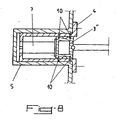
- Means with different mechanical strength properties than the rear zone 2 of dynamic plastic deformation, provided at the rear end of the vehicle are constituted, as shown in Figure 8 of the accompanying drawings, by a 3 "hitch support connected to an intermediate hitch body and cooperating with a box 4, housed in a chassis element 5 in the rear area 2 and fixed to said chassis, said hitch support 3 "resting in said box 4 on a energy absorbing element 7 and being connected to said box 4 by means of fuse bolts 10, the chassis 5 being further provided, at its end, with anti-overlapping devices not shown.
- the drawbar exerts on the support 3 "coupling force so that the fusible bolts 10 are sheared and the energy absorbing element 7 is crushed on the bottom of the box 4.
- the penetration of the drawbar 3 in the box 4 thus completely eliminates the risk of crutch and anti-overlapping devices, of known type, allow, by form cooperation, to avoid mutual vertical displacement between two car ends.
- a rail vehicle with driving cab comprising an energy absorbing structure, constituted by zones of dynamic plastic deformation, formed by absorbing elements fixed or interchangeable energy, allowing absorption of shock energy in progressive phases and ensuring maximum safety for the driver and The passengers.
Landscapes
- Engineering & Computer Science (AREA)
- Mechanical Engineering (AREA)
- Transportation (AREA)
- Chemical & Material Sciences (AREA)
- Combustion & Propulsion (AREA)
- Life Sciences & Earth Sciences (AREA)
- Wood Science & Technology (AREA)
- Vibration Dampers (AREA)
- Body Structure For Vehicles (AREA)
- Aiming, Guidance, Guns With A Light Source, Armor, Camouflage, And Targets (AREA)
Abstract
Description
La présente invention concerne le domaine de la construction métallique de véhicules, en particulier ferroviaires à cabine de conduite, et a pour objet un tel véhicule comportant une structure absorbeuse d'énergie à déformation progressive.The present invention relates to the field of construction metallic of vehicles, in particular railway with driving cab, and has for object such a vehicle comprising a deformation energy absorbing structure progressive.
Une telle structure a pour fonction de protéger les passagers et le conducteur du véhicule en cas de collision.The purpose of such a structure is to protect passengers and the driver of the vehicle in the event of a collision.
Les véhicules ferroviaires existant actuellement sont généralement équipés à leurs parties d'extrémité d'une structure destinée à supporter les sollicitations que subit le véhicule en conditions normales de circulation et lors de chocs à faible vitesse, dits chocs "d'accostage".Currently existing rail vehicles are generally equipped at their end parts with a structure intended to support the stresses to which the vehicle is subjected under normal traffic conditions and during low speed shocks, called "docking" shocks.
Cependant, en cas de chocs importants, notamment à vitesse relativement élevée, les véhicules existants ne présentent pas de disposition de protection des passagers et du conducteur par déformation préférentielle d'une partie de leur structure et absorption d'énergie, de sorte que lesdits passagers et le conducteur sont exposés à un risque important de dommages corporels en cas de tels chocs, le conducteur ne pouvant en particulier pas se réfugier dans une structure permettant sa survie.However, in the event of major shocks, especially at speed relatively high, existing vehicles do not have a protection of passengers and the driver by preferential deformation of a part of their structure and energy absorption, so that said passengers and the driver are exposed to a significant risk of personal injury in the event of such shocks, the driver being unable in particular to take refuge in a structure allowing its survival.
A cet effet, il a été proposé, par FR-A-2 698 840 un véhicule ferroviaire à cabine de conduite comportant une structure métallique absorbeuse d'énergie, consistant en des zones de déformation plastique dynamique, formées d'éléments absorbeurs d'énergie fixes ou interchangeables, prévues aux extrémités dudit véhicule. Une telle structure permet une absorption d'énergie sur une longueur importante par déformation plastique dynamique de zones prédéterminées, à savoir de l'avant de la cabine de conduite et au niveau des attelages des intercirculations.To this end, a vehicle has been proposed by FR-A-2 698 840 railway with driver's cab having an absorbent metallic structure of energy, consisting of zones of dynamic plastic deformation, formed fixed or interchangeable energy absorbing elements, provided at the ends of said vehicle. Such a structure allows energy absorption over a significant length by dynamic plastic deformation of zones predetermined, namely from the front of the driver's cab and at the level of the intercirculation couplings.
Un véhicule ferroviaire à cabine de conduite comportant une structure absorbeuse d'énergie est connu également de EP-A-0 655 556, du même Demandeur.A railway vehicle with a driving cabin comprising a energy absorbing structure is also known from EP-A-0 655 556, from the same Applicant.
Cependant, dans ce mode de réalisation, il est certes obtenu une déformation des zones concernées correspondant à une absorption totale de l'énergie du choc, mais cette déformation n'est pas totalement maítrisée dans sa progression.However, in this embodiment, it is certainly obtained a deformation of the areas concerned corresponding to a total absorption of the energy of the shock, but this deformation is not fully controlled in its progression.
La présente invention a pour but de pallier ces inconvénients en proposant un véhicule ferroviaire à cabine de conduite comportant une structure absorbeuse d'énergie à déformation progressive permettant de contrôler le sens de progression de la déformation lors d'un choc. The object of the present invention is to overcome these drawbacks by proposing a railway vehicle with a driving cabin comprising a structure energy absorber with progressive deformation allowing to control the direction of progression of the deformation during an impact.
Cet objectif est atteint au moyen des caractéristiques
inclues dans la Revendication 1.This objective is achieved by means of the characteristics
included in
L'invention sera mieux comprise, grâce à la description ci-après, qui
se rapporte à un mode de réalisation préféré, donné à titre d'exemple non limitatif,
et expliqué avec référence aux dessins schématiques annexés, dans lesquels :
Le véhicule ferroviaire à cabine de conduite représenté plus
particulièrement, à titre d'exemple, à la figure 1 des dessins annexés, comporte une
structure métallique absorbeuse d'énergie, qui consiste en des zones 1 et 2 de
déformation plastique dynamique, formées d'éléments absorbeurs d'énergie fixes
ou interchangeables, prévues respectivement aux extrémités avant et
d'intercirculation dudit véhicule.The railway cab vehicle shown more
particularly, by way of example, in Figure 1 of the accompanying drawings, comprises a
energy-absorbing metal structure, which consists of
Conformément à l'invention, les zones 1 et 2 de déformation
plastique dynamique présentent des moyens à propriété de résistance mécanique
différentes entraínant des phases de déformation progressive à partir de l'extrémité
correspondante du véhicule.In accordance with the invention, the
A cet effet, comme le montre la figure 2 des dessins annexés, les
moyens à propriété de résistance mécanique différentes de la zone 1 de
déformation plastique dynamique, prévue à l'extrémité avant du véhicule, sont
constitués par un attelage automatique 3 lié rigidement à un caisson 4 disposé dans
un élément de châssis 5, formé dans une partie d'extrémité indéformable 6 de la
caisse du véhicule, par un premier élément absorbeur d'énergie 7 inséré dans le
caisson 4 et s'appuyant contre l'extrémité arrière de l'attelage automatique 3, par au
moins un second élément absorbeur d'énergie 8 reliant la partie avant du caisson 4
à la face avant de la partie d'extrémité indéformable 6 de la caisse du véhicule et
par au moins une série d'éléments 9 et 9' à déformation plastique programmée,
prévus entre la partie d'extrémité indéformable 6 de la caisse du véhicule et la
caisse du véhicule proprement dite.To this end, as shown in Figure 2 of the accompanying drawings, the
means with properties of mechanical resistance different from
L'attelage automatique 3 est constitué par une tête d'attelage 3' et par
un corps reliant cette tête à un support d'attelage 3" lié rigidement au caisson 4 par
l'intermédiaire de boulons fusibles 10 (figures 2 et 4). Le montage ainsi réalisé
permet d'assurer le maintien en position de service de l'attelage automatique 3
dans une première phase d'absorption d'énergie correspondant à un choc
n'excédant pas une vitesse de l'ordre de 7 km/h, correspondant à une sollicitation
mécanique des boulons fusibles 10 inférieure à leur limite de rupture par
cisaillement, ledit attelage automatique 3 réalisant alors l'absorption d'énergie sans
déformation (figure 4).The
Le premier élément absorbeur d'énergie 7, inséré dans le caisson 4 et
s'appuyant contre l'extrémité arrière de l'attelage automatique 3, est
avantageusement constitué par une pièce en matière composite destructible sous
forme d'un tube reliée par son extrémité avant au support d'attelage 3" de l'attelage
automatique 3 et s'appuyant par son extrémité arrière sur le fond du caisson 4, ce
fond présentant au moins une ouverture, non représentée, d'éjection de la matière
constitutive de l'élément absorbeur d'énergie 7, ladite ouverture ayant une section
inférieure à celle du tube. De préférence, le tube constituant l'élément absorbeur
d'énergie 7 s'appuie sur un élément de section correspondante du fond du caisson
4, cet élément d'appui présentant deux ouvertures d'éjection de la matière
constitutive de l'élément absorbeur d'énergie 7, diamétralement opposées.The first
Le caisson 4 présente une partie arrière tubulaire de réception du
corps et du support d'attelage 3" de l'attelage automatique 3 et une partie
antérieure évasée de réception de la tête 3' dudit attelage automatique 3 pourvue
de bords latéraux 4' destinés à coopérer avec le ou les seconds éléments
absorbeurs d'énergie 8, la face avant de ces bords 4' étant munie de dispositifs 4"
d'antichevauchement. Ces dispositifs 4" sont de type connu et permettent, par
coopération de forme, d'éviter un déplacement vertical mutuel entre deux
extrémités de voitures. The
Ainsi, dans le cas d'un choc d'une intensité supérieure à la limite de
résistance de rupture par cisaillement des boulons fusibles 10, ces derniers sont
détruits et l'attelage automatique 3 est poussé vers le fond de la partie arrière
tubulaire du caisson 4, entraínant l'élément absorbeur d'énergie 7, qui est alors
écrasé dans ledit caisson 4, sa matière constitutive étant éjectée à travers la ou les
ouvertures d'éjection prévues dans ledit caisson 4 (figure 5). A la fin de cette
phase d'absorption d'énergie, l'attelage automatique 3 est entièrement logé dans le
caisson 4, l'élément absorbeur d'énergie 7 étant totalement détruit et expulsé dudit
caisson. Cette deuxième phase d'absorption d'énergie correspond à une vitesse de
choc comprise entre 7 km/h et 18 km/h et permet une remise en état rapide par
simples remplacement de l'élément absorbeur d'énergie 7 et mise en place de
nouveaux boulons fusibles 10.Thus, in the case of a shock of an intensity greater than the limit of
shear breaking strength of
L'élément de châssis 5, formé dans une partie d'extrémité
indéformable 6, présente, d'une part, à son extrémité opposée à celle recevant le
caisson 4, une ouverture 11 destinée à permettre l'éjection de la matière
constitutive de l'élément absorbeur d'énergie 7 lors de l'écrasement de ce dernier
et, d'autre part, une longueur au moins égale à celle de la partie arrière tubulaire du
caisson 4 (figures 4 à 7).The frame member 5, formed in an end portion
non-deformable 6, presents, on the one hand, at its end opposite to that receiving the
Les seconds éléments absorbeurs d'énergie 8 reliant la partie avant du
caisson 4 à la face avant de la partie d'extrémité indéformable 6 de la caisse du
véhicule se présentent sous forme de poutres déformables boulonnées à leurs
extrémités, respectivement sur l'avant de la partie d'extrémité indéformable 6 de la
caisse du véhicule et sur la face arrière des bords 4' du caisson 4, ces poutres
déformables étant constituées chacune par un assemblage de tôles à déformation
prédéterminée. Des structures déformables de ce type sont notamment connues par
FR-A-2 694 255.The second
Ces seconds éléments absorbeurs d'énergie 8 permettent, comme le
montre la figure 6 des dessins annexés, une troisième phase d'absorption de chocs
par déformation plastique irréversible, pour des vitesses de choc allant jusqu'à 32
km/h.These second
La constitution de l'élément de châssis 5 permet, lors de la troisième
phase d'absorption d'énergie, un escamotage complet de la partie arrière tubulaire
de réception du corps et du support d'attelage 3" de l'attelage automatique 3, du
caisson 4 avec l'attelage automatique 3, dans ledit élément de châssis 5. Les
parties avant de l'attelage automatique 3 et du caisson 4 logent alors dans le
bouclier 6' prévu à l'extrémité avant de la partie d'extrémité indéformable 6 de la
caisse du véhicule et suppriment ainsi totalement le risque de béquillage. The constitution of the chassis element 5 allows, during the third
energy absorption phase, complete retraction of the tubular rear part
for receiving the body and the 3 "hitch support of the
La ou les séries d'éléments 9 et 9' à déformation plastique
programmée, prévus entre la partie d'extrémité indéformable 6 de la caisse du
véhicule et la caisse du véhicule proprement dite se présentent avantageusement
sous forme d'assemblages de tôles à déformation progressive à partir de l'avant
vers l'arrière du véhicule (figures 3 et 7). Ces éléments 9 et 9' constituent le
châssis s'étendant entre la partie d'extrémité indéformable 6 de la caisse du
véhicule et la caisse du véhicule proprement dite et sont reliés à des arceaux
rigides 12 de ces derniers.The series or
Les éléments 9 et 9' sont, de préférence, prévus par paires et sont
reliés à un arceau intermédiaire 13 délimitant latéralement une ouverture de porte
et un local technique. Ainsi, les éléments 9 et 9' entre deux arceaux sont limités à
un nombre restreint, de sorte que leur déformation peut s'effectuer uniquement par
écrasement, sans flambage généralisé.
Selon une caractéristique de l'invention, la cabine de conduite du
véhicule est pourvue d'un tunnel de survie 14 sous forme d'une cage en treillis
tubulaire, monté entre une traverse de pivot 16 et le toit de la cabine et fixé sur
l'arceau rigide 12 délimitant la caisse du véhicule proprement dite (figure 4).According to a characteristic of the invention, the driver's cab of the
vehicle is provided with a survival tunnel 14 in the form of a trellis cage
tubular, mounted between a pivot cross member 16 and the roof of the cabin and fixed on
the
De préférence, dans le cas de la prévision d'une paire d'éléments 9
et 9' s'étendant de part et d'autre d'un arceau intermédiaire 13, les éléments 9'
situés entre l'arceau intermédiaire 13 et l'arceau rigide 12 délimitant la caisse du
véhicule proprement dite sont disposés de telle manière que leur déformation
progressive s'effectue à partir de l'arrière vers l'avant du véhicule.Preferably, in the case of the forecast of a pair of
Ces éléments 9 et 9' sont constitués, comme le montre la figure 3
des dessins annexés, sous forme de caissons, dont les faces latérales et centrales
s'étendant parallèlement à l'axe longitudinal du véhicule présentent des
allégements de matière sous forme d'ouvertures 15 ou des prédéformations sous
forme d'ondulations de matière. Les ouvertures 15 des éléments 9 et 9' présentent
avantageusement une section décroissante en direction de la déformation et les
ondulations des éléments 9 et 9' présentent un amplitude décroissante dans la
même direction. Ainsi, la résistance des éléments 9 et 9' s'accroít au fur et à
mesure de la déformation de la zone 1.These
Conformément à une autre caractéristique de l'invention, les tôles
formant les assemblages de tôles constitutifs des éléments 9 et 9' présentent une
épaisseur croissante en direction de la déformation. Ainsi, la résistance des
éléments 9 et 9' augmente également pendant la phase de déformation. In accordance with another characteristic of the invention, the sheets
forming the assemblies of sheets constituting the
Cette déformation des éléments 9 et 9' correspond à une quatrième
phase d'absorption d'énergie, qui est déclenchée à partir d'une vitesse de l'ordre de
32 km/h et permet de préserver un espace suffisant pour le tunnel de survie 14.This deformation of the
Le fait de prévoir, entre l'arceau intermédiaire 13 et l'arceau 12
délimitant la caisse du véhicule proprement dite, des éléments 9 et 9' dont la
déformation s'effectue progressivement, permet d'optimaliser la déformation du
tronçon de cabine correspondant en protégeant simultanément le tunnel 14 et les
armoires techniques pouvant être ménagées de part et d'autre de ce dernier.Providing, between the
Les moyens à propriété de résistance mécanique différentes de la
zone arrière 2 de déformation plastique dynamique, prévue à l'extrémité arrière du
véhicule sont constitués, comme le montre la figure 8 des dessins annexés, par un
support d'attelage 3" relié à un corps intermédiaire de barre d'attelage et coopérant
avec un caisson 4, logé dans un élément de châssis 5 de la zone arrière 2 et fixé
audit châssis, ledit support d'attelage 3" s'appuyant dans ledit caisson 4 sur un
élément absorbeur d'énergie 7 et étant relié audit caisson 4 par l'intermédiaire de
boulons fusibles 10, le châssis 5 étant pourvu, en outre, à son extrémité, de
dispositifs d'antichevauchement non représentés. Il résulte de ce mode de
réalisation que lors d'un choc violent, la barre d'attelage exerce sur le support
d'attelage 3" un effort tel que les boulons fusibles 10 soient cisaillés et que
l'élément absorbeur d'énergie 7 soit écrasé sur le fond du caisson 4. La pénétration
de la barre d'attelage 3 dans le caisson 4 supprime ainsi totalement le risque de
béquillage et des dispositifs d'antichevauchement, de type connu, permettent, par
coopération de forme, d'éviter un déplacement vertical mutuel entre deux
extrémités de voitures.Means with different mechanical strength properties than the
Grâce à l'invention, il est possible de réaliser un véhicule ferroviaire à cabine de conduite comportant une structure absorbeuse d'énergie, constituée par des zones de déformation plastique dynamique, formées d'éléments absorbeurs d'énergie fixes ou interchangeables, permettant une absorption de l'énergie de choc par phases progressives et assurant une sécurité maximale pour le conducteur et les passagers.Thanks to the invention, it is possible to produce a rail vehicle with driving cab comprising an energy absorbing structure, constituted by zones of dynamic plastic deformation, formed by absorbing elements fixed or interchangeable energy, allowing absorption of shock energy in progressive phases and ensuring maximum safety for the driver and The passengers.
Bien entendu, l'invention n'est pas limitée au mode de réalisation décrit et représenté aux dessins annexés. Des modifications restent possibles, notamment du point de vue de la constitution des divers éléments ou par substitution d'équivalents techniques, sans sortir pour autant du domaine de protection de l'invention.Of course, the invention is not limited to the embodiment described and shown in the accompanying drawings. Modifications are still possible, in particular from the point of view of the constitution of the various elements or by substitution of technical equivalents, without departing from the scope of protection of the invention.
Claims (17)
- A rail vehicle with a driver's cab including an energy-absorbing structure consisting of respective dynamic plastic deformation areas (1 and 2) formed of fixed or interchangeable energy-absorbing members at front and between-cars ends of said vehicle, the dynamic plastic deformation areas (1 and 2) having means with different mechanical strength properties leading to progressive-deformation phases from the corresponding end of the vehicle, characterised in that the means with different mechanical properties of the dynamic plastic deformation area (1) at the front end of the vehicle consist of an automatic coupling (3) connected rigidly to a first box-section (4) disposed in a chassis member (5) formed in a non-deformable end part (6) of the body of the vehicle, a first energy-absorbing member (7) inserted in the box-section (4) and bearing against the rear end of the automatic coupling (3), a second energy-absorbing member (8) connecting the front part of the box-section (4) to the front face of the non-deformable end part (6) of the body of the vehicle, and a series of members (9 and 9') which undergo programmed plastic deformation disposed between the non-deformable end part (6) of the body of the vehicle and the body itself.
- A rail vehicle according to claim 1, characterised in that the automatic coupling (3) consists of a coupling head (3') and a body connecting said head to a coupling support (3") connected rigidly to the box-section (4) by breakable bolts (10).
- A rail vehicle according to either claim 1 or claim 2, characterised in that the first energy-absorbing member (7) inserted in the box-section (4) and bearing against the rear end of the automatic coupling (3) consists of a composite material destructible component in the form of a tube connected at its front end to the coupling support (3") of the automatic coupling (3) and with its rear end bearing on the end wall of the box-section (4), that end wall having an opening in it of smaller section than the tube for ejection of the material of the energy-absorbing member (7).
- A rail vehicle according to claim 3, characterised in that the tube constituting the energy-absorbing member (7) bears on a member of corresponding section of the end wall of the box-section (4) having two diametrally opposite openings in it for ejecting the material of the energy-absorbing member (7).
- A rail vehicle according to any of claims 1 to 4, characterised in that the box-section (4) has a tubular rear part to receive the body and the coupling support (3") of the automatic coupling (3) and a flared front part to receive the head (3') of said automatic coupling (3) provided with lateral rim (4') adapted to cooperate with the second energy-absorbing member or members (8), the front face of the rims (4') being provided with anti-override devices (4").
- A rail vehicle according to any of claims 1 to 5, characterised in that the chassis member (5) formed in a non-deformable end part (6) is at least as long as the tubular rear part of the box-section (4) and has at the end opposite that receiving the box-section (4) an opening (11) to enable ejection of the material of the energy-absorbing member (7) during crushing of the latter.
- A rail vehicle according to any of claims 1 to 3, 5 or 6, characterised in that the second energy-absorbing member or members (8) connecting the front part of the box-section (4) to the front face of the non-deformable end part (6) of the body of the vehicle takes the form of deformable beams bolted at their respective ends to the front of the non-deformable end part (6) of the body of the vehicle and to the rear face of the rims (4') of the box-section (4), each deformable beam consisting of an assembly of plates which deform in a predetermined way.
- A rail vehicle according to claim 1, characterised in that the series of members (9 and 9') that undergo programmed plastic deformation between the non-deformable end part (6) of the body of the vehicle and the body itself take the form of assemblies of plates which deform progressively from the front towards the rear of the vehicle.
- A rail vehicle according to claim 8, characterised in that the members (9 and 9') that undergo programmed plastic deformation constitute a chassis between the non-deformable end part (6) of the body of the vehicle and the body itself and are connected to rigid arched members (12) of the latter.
- A rail vehicle according to either claim 8 or claim 9, characterised in that the members (9 and 9') that undergo programmed plastic deformation are provided in pairs and are joined to an intermediate arched member (13) delimiting laterally a door opening and a technical area.
- A rail vehicle according to any of claims 1 and 8 to it [sic], characterised in that the driver's cab is provided with a survival tunnel (14) in the form of a tubular mesh cage mounted between a pivot crossmember (16) and the roof of the cab and fixed to the rigid arched member (12) delimiting the body of the vehicle.
- A rail vehicle according to claim 10, characterised in that the members (9') that undergo programmed plastic deformation between the intermediate arched member (13) and the rigid arched member (12) delimiting the body of the vehicle are disposed so that they deform progressively from the rear towards the front of the vehicle.
- A rail vehicle according to any of claims 1 and 8 to 12, characterised in that the members (9 and 9') that undergo programmed plastic deformation take the form of box-sections whose lateral and central faces are parallel to the longitudinal axis of the vehicle and are weakened by openings (15) or corrugations.
- A rail vehicle according to claim 13, characterised in that the openings (15) in the members (9 and 9') that undergo programmed plastic deformation advantageously have a section that decreases in the direction of deformation and the corrugations advantageously have an amplitude decreasing in the same direction.
- A rail vehicle according to any of claims 1 and 8 to 14, characterised in that the plates forming the assembly of plates constituting the members (9 and 9') that undergo programmed plastic deformation have a thickness increasing in the direction of deformation.
- A rail vehicle according to any of claims 1 to 7, characterised in that the means with different mechanical strength properties of the rear dynamic plastic deformation area (2) at the rear end of the vehicle consist of a coupling support (3") connected to an intermediate coupling bar body and co-operating with a box-section (4) housed in a chassis member (5) of the rear area (2) and fixed to said chassis, said coupling support (3") bearing inside said box-section (4) on an energy-absorbing member (7) and being connected to said box section (4) by breakable bolts (10), and the chassis (5) being further provided at its end with anti-override devices.
- A rail vehicle according to any of claims 1, 3 to 7 and 16, characterised in that the energy-absorbing members (7 and 8) take the form of interchangeable members that can be replaced readily in the event of a destructive impact.
Applications Claiming Priority (2)
| Application Number | Priority Date | Filing Date | Title |
|---|---|---|---|
| FR9605203 | 1996-04-19 | ||
| FR9605203A FR2747633B1 (en) | 1996-04-19 | 1996-04-19 | RAILWAY VEHICLE WITH DRIVING CABIN COMPRISING AN ENERGY ABSORBING STRUCTURE WITH PROGRESSIVE DEFORMATION |
Publications (2)
| Publication Number | Publication Date |
|---|---|
| EP0802100A1 EP0802100A1 (en) | 1997-10-22 |
| EP0802100B1 true EP0802100B1 (en) | 2001-09-12 |
Family
ID=9491569
Family Applications (1)
| Application Number | Title | Priority Date | Filing Date |
|---|---|---|---|
| EP97440039A Expired - Lifetime EP0802100B1 (en) | 1996-04-19 | 1997-04-18 | Railway vehicle with a driverscompartment having an energy absorbing structure with progressive deformation |
Country Status (7)
| Country | Link |
|---|---|
| EP (1) | EP0802100B1 (en) |
| AT (1) | ATE205448T1 (en) |
| DE (1) | DE69706597T2 (en) |
| DK (1) | DK0802100T3 (en) |
| ES (1) | ES2161423T3 (en) |
| FR (1) | FR2747633B1 (en) |
| PT (1) | PT802100E (en) |
Cited By (1)
| Publication number | Priority date | Publication date | Assignee | Title |
|---|---|---|---|---|
| DE102006002036A1 (en) * | 2006-01-16 | 2007-07-26 | Siemens Ag | Relay locker assembling method for use in rail vehicle, involves positioning locker in driver's cab through section using lifting device, where section is provided in vehicle roof and designed for mounting of air-conditioning system |
Families Citing this family (77)
| Publication number | Priority date | Publication date | Assignee | Title |
|---|---|---|---|---|
| FR2765543B1 (en) | 1997-07-02 | 2005-01-07 | Alstom Ddf | RAILWAY VEHICLE COMPRISING AT LEAST ONE INTERCHANGEABLE END MODULE |
| DE19817860A1 (en) * | 1998-04-22 | 1999-11-04 | Dwa Deutsche Waggonbau Gmbh | Safety device for vehicle drivers of rail vehicles |
| DE19817861C2 (en) * | 1998-04-22 | 2001-09-06 | Dwa Deutsche Waggonbau Gmbh | Collision protection device for rail vehicles |
| FR2785028B1 (en) | 1998-10-23 | 2000-12-15 | Dytesys | SHOCK ABSORBER DEVICE |
| ES2193680T3 (en) | 1999-10-06 | 2003-11-01 | Alcan Tech & Man Ag | DEVICE FOR THE IMPACT ENERGY ABSORPTION. |
| DE19956856A1 (en) | 1999-11-25 | 2001-05-31 | Siemens Duewag Gmbh | Rail vehicle, especially for passenger conveyance on outer suburban rail services, has shock absorber units supported on deformable sandwich construction containing foam metal and supporting section of footplate of driver's cab |
| ES2275706T3 (en) * | 2000-08-28 | 2007-06-16 | Mitsubishi Heavy Industries, Ltd. | BODY STRUCTURE. |
| FR2818224B1 (en) * | 2000-12-18 | 2003-01-24 | Alstom | RAIL VEHICLE WITH DRIVING CABIN COMPRISING AN ENERGY ABSORBING STRUCTURE SUITABLE FOR COLLISION ABOVE THE VEHICLE CHASSIS |
| DE10152986A1 (en) * | 2001-10-26 | 2003-05-08 | Siemens Ag | Climbing protection device for rail vehicles with side buffers |
| DE10155257B4 (en) * | 2001-11-09 | 2008-02-21 | Alstom Lhb Gmbh | Collision protection device for rail vehicles |
| JP3848227B2 (en) * | 2002-09-02 | 2006-11-22 | 株式会社日立製作所 | Rail vehicle |
| JP4912559B2 (en) * | 2002-09-11 | 2012-04-11 | 株式会社日立製作所 | Rail vehicle |
| DE10301273A1 (en) * | 2003-01-15 | 2004-04-22 | Siemens Ag | Railcar kinetic collision energy converter involves modules joined to car structure stiffly but otherwise drilled out to form deformable crush sectors to absorb kinetic energy of collision etc. |
| DE10321238B4 (en) * | 2003-05-12 | 2014-08-07 | Siemens Aktiengesellschaft | Rail vehicle with nose cone |
| ES2300829T3 (en) | 2003-09-19 | 2008-06-16 | Siemens Transportation Systems Inc. | INTEGRATED IMPACT PROTECTION SYSTEM. |
| DE102004003142A1 (en) * | 2004-01-21 | 2005-08-18 | Siemens Ag | Rail vehicle with a car body stem |
| GB2411633A (en) * | 2004-03-01 | 2005-09-07 | Bombardier Transp Gmbh | Railway vehicle with cabin having a collapsible front section |
| GB2411632A (en) | 2004-03-01 | 2005-09-07 | Bombardier Transp Gmbh | Rail vehicle cabin with yieldable parts |
| DE102004028964A1 (en) | 2004-05-07 | 2005-12-01 | Siemens Ag | Vehicle with deformation zone |
| DE202005004885U1 (en) * | 2005-03-26 | 2006-08-03 | Alstom Lhb Gmbh | Floor education with floor plate in the driver's cab of rail vehicles |
| JP4912614B2 (en) * | 2005-05-09 | 2012-04-11 | 株式会社日立製作所 | Rail vehicle |
| JP4712604B2 (en) * | 2006-05-10 | 2011-06-29 | 株式会社日立製作所 | Transport equipment |
| JP5179053B2 (en) * | 2006-05-10 | 2013-04-10 | 株式会社日立製作所 | Collision energy absorbing device and rail vehicle equipped with the same |
| EP1873036B1 (en) | 2006-05-10 | 2012-02-22 | Hitachi, Ltd. | Collision energy absorbing device and railway vehicle comprising such a device |
| KR100797046B1 (en) | 2006-09-05 | 2008-01-22 | 한국철도기술연구원 | Apparatus for absorbing shock power of sliding type |
| DE102006043926A1 (en) * | 2006-09-14 | 2008-03-27 | Voith Turbo Lokomotivtechnik Gmbh & Co. Kg | locomotive |
| DE102006044397A1 (en) * | 2006-09-18 | 2008-03-27 | Bombardier Transportation Gmbh | Head module for a rail vehicle |
| JP4845688B2 (en) * | 2006-11-21 | 2011-12-28 | 株式会社日立製作所 | vehicle |
| ITTO20060863A1 (en) | 2006-12-04 | 2008-06-05 | Ansaldobreda Spa | HEAD CAR OF A TRAIN PROVIDED WITH A FRONT STRUCTURE THAT ABSORTS ENERGY IN CASE OF COLLISION |
| DE102008007590A1 (en) * | 2008-01-31 | 2009-08-06 | Siemens Aktiengesellschaft | Head assembly for forming the front of a vehicle |
| JP2009241772A (en) * | 2008-03-31 | 2009-10-22 | Hitachi Ltd | Rail vehicle |
| EP2130739B1 (en) | 2008-06-06 | 2013-09-25 | Bombardier Transportation GmbH | Rail car underframe assembly and modular car body for a rail vehicle |
| AU2009290832B2 (en) | 2008-09-15 | 2012-04-12 | Voith Patent Gmbh | Vehicle front-end for mounting to the front face of a track-bound vehicle, in particular a rail vehicle |
| ES2362167T5 (en) * | 2009-09-15 | 2017-09-06 | Voith Patent Gmbh | Energy absorption device, in particular in the form of impact protection for a rail-guided vehicle |
| JP5161251B2 (en) * | 2010-03-25 | 2013-03-13 | 株式会社日立製作所 | Railway vehicle with shock absorbing structure |
| JP5209666B2 (en) * | 2010-05-10 | 2013-06-12 | 日本車輌製造株式会社 | Railway vehicle |
| CN101817350B (en) * | 2010-05-10 | 2011-12-21 | 南车株洲电力机车有限公司 | Cab |
| WO2011142208A1 (en) * | 2010-05-10 | 2011-11-17 | 日本車輌製造株式会社 | Railroad vehicle |
| CN102180182A (en) * | 2011-03-30 | 2011-09-14 | 中南大学 | Coupler buffer device with cutting type energy-absorbing bumper |
| WO2013079733A1 (en) * | 2011-11-30 | 2013-06-06 | Patentes Talgo, S.L. | Energy absorption system for the caboose of railway vehicles |
| US9248846B2 (en) * | 2011-12-02 | 2016-02-02 | Nippon Sharyo, Ltd. | Rolling stock |
| JP5752277B2 (en) * | 2012-01-27 | 2015-07-22 | 日本車輌製造株式会社 | Railway vehicle |
| CN102975731B (en) * | 2012-04-24 | 2015-08-12 | 南车南京浦镇车辆有限公司 | The mounting structure of railway vehicle cab skeleton and car body |
| DE102012212967A1 (en) * | 2012-07-24 | 2014-01-30 | Siemens Aktiengesellschaft | Zugkopfteil |
| CN103101553B (en) * | 2013-03-06 | 2015-04-22 | 南车南京浦镇车辆有限公司 | Front-end train assembly with anti-creeping energy-absorbing device |
| CN103192845B (en) * | 2013-04-22 | 2015-09-30 | 西南交通大学 | The anti-bias energy absorption device of a kind of anti-creep |
| AT514375B1 (en) * | 2013-06-04 | 2015-02-15 | Siemens Ag Oesterreich | Rail vehicle with deformation zone |
| CN104442857B (en) * | 2013-09-22 | 2017-10-03 | 中车青岛四方机车车辆股份有限公司 | A kind of railway vehicle cab endergonic structure |
| CN103625500B (en) * | 2013-10-10 | 2016-09-07 | 中车青岛四方机车车辆股份有限公司 | Chassis of rail vehicle end portion anti-collision structure |
| CN103625501B (en) * | 2013-10-17 | 2016-06-22 | 中车青岛四方机车车辆股份有限公司 | A kind of rail vehicle anti-creep buffer structure |
| CN103625502B (en) * | 2013-10-18 | 2016-05-25 | 中车青岛四方机车车辆股份有限公司 | A kind of rail vehicle front end energy absorption device |
| CN103770798A (en) * | 2014-02-11 | 2014-05-07 | 唐山轨道客车有限责任公司 | Train front end structure and train |
| CN104787073A (en) * | 2015-03-26 | 2015-07-22 | 长春轨道客车股份有限公司 | Head-train under carriage end structure of high speed EMU |
| CN104943702B (en) * | 2015-06-30 | 2018-08-03 | 中车青岛四方机车车辆股份有限公司 | A kind of partition wall and the rail vehicle with the partition wall |
| CN105151075B (en) * | 2015-09-30 | 2018-03-20 | 中车青岛四方机车车辆股份有限公司 | A kind of energy absorption device and the rail vehicle with the energy absorption device |
| US11021176B2 (en) | 2015-09-30 | 2021-06-01 | Crrc Qingdao Sifang Co., Ltd. | Energy absorption device and rail vehicle having same |
| CN105292164B (en) * | 2015-10-16 | 2017-11-14 | 中南大学 | Telescopic rail energy-absorbing device for vehicle collision |
| GB201522419D0 (en) * | 2015-12-18 | 2016-02-03 | Hitachi Ltd | Railway vehicle provided with collision energy absorption structure |
| CN105818831B (en) * | 2016-03-31 | 2017-10-24 | 中南大学 | Combined type energy absorber and the rail vehicle with the combined type energy absorber |
| CN105946890A (en) * | 2016-06-20 | 2016-09-21 | 中车唐山机车车辆有限公司 | Energy absorption device and rail vehicle |
| CN106240587B (en) * | 2016-08-30 | 2018-12-14 | 中车株洲电力机车有限公司 | A kind of rail vehicle vehicle head structure |
| CN106240595B (en) * | 2016-09-28 | 2018-02-23 | 中南大学 | A kind of collision energy-absorbing device used for rail vehicle |
| CN106364520B (en) * | 2016-09-28 | 2018-04-13 | 中南大学 | A kind of train collision means of defence and system |
| CN106347387B (en) * | 2016-10-09 | 2019-02-26 | 中车株洲电力机车有限公司 | A kind of rail vehicle head bassinet structure |
| CN106672010A (en) * | 2016-11-22 | 2017-05-17 | 中车长春轨道客车股份有限公司 | Motor train unit head train passive safety protection device |
| WO2018112684A1 (en) * | 2016-12-19 | 2018-06-28 | 中车株洲电力机车有限公司 | Locomotive structure of railway vehicle |
| CN107200034A (en) * | 2017-05-23 | 2017-09-26 | 中车唐山机车车辆有限公司 | Energy-absorbing component and motor-car |
| CN108482414B (en) * | 2018-03-26 | 2019-06-11 | 中车株洲电力机车有限公司 | Rail vehicle and its rail vehicle lead slow structure |
| JP7218060B2 (en) * | 2019-03-29 | 2023-02-06 | 日本車輌製造株式会社 | rail car |
| CN110920650B (en) * | 2019-09-18 | 2021-04-16 | 中车南京浦镇车辆有限公司 | Front-end anti-collision structure of underframe of railway vehicle |
| CN112977518B (en) * | 2019-12-13 | 2023-02-28 | 中车唐山机车车辆有限公司 | Rail vehicle and vehicle body and end underframe thereof |
| CN111605568A (en) * | 2020-07-03 | 2020-09-01 | 中车戚墅堰机车有限公司 | Diesel locomotive cab with multistage collision protection |
| CN112078620B (en) * | 2020-09-16 | 2021-09-17 | 中车株洲电力机车有限公司 | Front end structure of railway vehicle |
| CN112078618B (en) * | 2020-09-16 | 2022-01-18 | 中车株洲电力机车有限公司 | Rail vehicle chassis structure |
| CN112109764B (en) * | 2020-09-16 | 2021-09-17 | 中车株洲电力机车有限公司 | Car stopper and rail vehicle anti-collision method |
| CN112109758B (en) * | 2020-09-16 | 2021-10-26 | 中车株洲电力机车有限公司 | Rail vehicle anti-collision system and method |
| CN112389488B (en) * | 2020-11-02 | 2022-05-17 | 中车唐山机车车辆有限公司 | Rail vehicle and cab vehicle thereof |
Family Cites Families (3)
| Publication number | Priority date | Publication date | Assignee | Title |
|---|---|---|---|---|
| DE635018C (en) * | 1933-01-14 | 1936-09-14 | Curt Stedefeld Dipl Ing | Streamlined head part with a rear-mounted driver's cab structure for high-speed railcars |
| GB2257770A (en) * | 1991-07-16 | 1993-01-20 | Fischer Georg Formtech | Shock absorber for a coupling |
| FR2712950B1 (en) * | 1993-11-25 | 1995-12-29 | Gec Alsthom Transport Sa | Shock absorbing devices and method, frame and vehicle comprising such shock absorbing devices. |
-
1996
- 1996-04-19 FR FR9605203A patent/FR2747633B1/en not_active Expired - Fee Related
-
1997
- 1997-04-18 ES ES97440039T patent/ES2161423T3/en not_active Expired - Lifetime
- 1997-04-18 AT AT97440039T patent/ATE205448T1/en not_active IP Right Cessation
- 1997-04-18 PT PT97440039T patent/PT802100E/en unknown
- 1997-04-18 DE DE69706597T patent/DE69706597T2/en not_active Expired - Fee Related
- 1997-04-18 EP EP97440039A patent/EP0802100B1/en not_active Expired - Lifetime
- 1997-04-18 DK DK97440039T patent/DK0802100T3/en active
Cited By (2)
| Publication number | Priority date | Publication date | Assignee | Title |
|---|---|---|---|---|
| DE102006002036A1 (en) * | 2006-01-16 | 2007-07-26 | Siemens Ag | Relay locker assembling method for use in rail vehicle, involves positioning locker in driver's cab through section using lifting device, where section is provided in vehicle roof and designed for mounting of air-conditioning system |
| DE102006002036B4 (en) * | 2006-01-16 | 2014-07-17 | Siemens Aktiengesellschaft | Method for installing a device cabinet in the driver's compartment of a rail vehicle |
Also Published As
| Publication number | Publication date |
|---|---|
| PT802100E (en) | 2002-01-30 |
| ES2161423T3 (en) | 2001-12-01 |
| DK0802100T3 (en) | 2001-12-17 |
| FR2747633B1 (en) | 2003-01-31 |
| DE69706597D1 (en) | 2001-10-18 |
| ATE205448T1 (en) | 2001-09-15 |
| FR2747633A1 (en) | 1997-10-24 |
| DE69706597T2 (en) | 2002-07-11 |
| EP0802100A1 (en) | 1997-10-22 |
Similar Documents
| Publication | Publication Date | Title |
|---|---|---|
| EP0802100B1 (en) | Railway vehicle with a driverscompartment having an energy absorbing structure with progressive deformation | |
| CA2121995C (en) | Shock absorbing device | |
| EP0655565B1 (en) | Shock absorbing devices and methods, frame and vehicle having such shock absorbing devices | |
| CA2364957C (en) | Rail vehicle with a conductor's car comprising a collision energy absorbing structure above the vehicle chassis | |
| EP1893469B1 (en) | Guided low area for the front of a motor vehicle | |
| EP1827943B1 (en) | Shock absorber device for railway vehicle | |
| EP1942033B1 (en) | Support part for a shock-absorber system designed to be mounted on one end of a longitudinal beam for a vehicle | |
| FR2698840A1 (en) | Energy-absorbing driver cab for rail vehicle - has two zones with dynamic plastic deformation and fixed or interchangeable energy absorbers using automatic coupling with two slides | |
| EP1426242A2 (en) | Bumper beam with twin shells and a stiffening element | |
| EP2934953B1 (en) | Shock absorbing apparatus for a front vehicle structure | |
| EP0581707B1 (en) | Structure for energy absorption, especially for railway vehicles | |
| WO2006072695A2 (en) | Front panel for motor vehicle | |
| WO2018109294A1 (en) | Underbody structure of an automotive vehicle, in particular a hybrid automotive vehicle, adapted for a lateral shock | |
| FR3092067A1 (en) | Motor cradle for a motor vehicle and a vehicle comprising such a cradle | |
| EP1660364B1 (en) | Motor vehicle forebody structure | |
| FR3022603B1 (en) | ENERGY ABSORBER DEVICE AND CORRESPONDING VEHICLE | |
| EP1106467A1 (en) | Device for controlled deformation by forces or for absorption of energy by deformation, especially obstacle deflector for a railway vehicle | |
| EP2767458B1 (en) | Floor of rear luggage compartment for a motor vehicle, comprising a reinforced beam | |
| EP4001060B1 (en) | Front structure of a motor vehicle with frontal collision management with small overlap | |
| EP3424757B1 (en) | Automotive vehicle rear train comprising means for absorbing the energy of a side impact | |
| FR3081423A1 (en) | VEHICLE WITH ABSORPTION DEVICE WITH INCREASING IMPACT SURFACE DURING SHOCK. | |
| FR2742776A1 (en) | Protection element used at racetracks for absorbing shocks of impact between vehicles and fixed obstacles | |
| FR3041580A1 (en) | VEHICLE STRUCTURE COMPRISING A REINFORCEMENT DEVICE AND VEHICLE COMPRISING SUCH A STRUCTURE | |
| CA2466204C (en) | Method for absorbing impact and frame | |
| FR2862596A1 (en) | LIGHT VEHICLE OF A NEW TYPE |
Legal Events
| Date | Code | Title | Description |
|---|---|---|---|
| PUAI | Public reference made under article 153(3) epc to a published international application that has entered the european phase |
Free format text: ORIGINAL CODE: 0009012 |
|
| AK | Designated contracting states |
Kind code of ref document: A1 Designated state(s): AT BE CH DE DK ES GB IT LI NL PT SE |
|
| 17P | Request for examination filed |
Effective date: 19980313 |
|
| RAP1 | Party data changed (applicant data changed or rights of an application transferred) |
Owner name: ALSTOM DDF |
|
| 17Q | First examination report despatched |
Effective date: 19991223 |
|
| GRAG | Despatch of communication of intention to grant |
Free format text: ORIGINAL CODE: EPIDOS AGRA |
|
| GRAH | Despatch of communication of intention to grant a patent |
Free format text: ORIGINAL CODE: EPIDOS IGRA |
|
| GRAH | Despatch of communication of intention to grant a patent |
Free format text: ORIGINAL CODE: EPIDOS IGRA |
|
| GRAA | (expected) grant |
Free format text: ORIGINAL CODE: 0009210 |
|
| AK | Designated contracting states |
Kind code of ref document: B1 Designated state(s): AT BE CH DE DK ES GB IT LI NL PT SE |
|
| REF | Corresponds to: |
Ref document number: 205448 Country of ref document: AT Date of ref document: 20010915 Kind code of ref document: T |
|
| REG | Reference to a national code |
Ref country code: CH Ref legal event code: EP |
|
| GBT | Gb: translation of ep patent filed (gb section 77(6)(a)/1977) |
Effective date: 20010912 |
|
| REG | Reference to a national code |
Ref country code: CH Ref legal event code: NV Representative=s name: CABINET ROLAND NITHARDT CONSEILS EN PROPRIETE INDU |
|
| REF | Corresponds to: |
Ref document number: 69706597 Country of ref document: DE Date of ref document: 20011018 |
|
| REG | Reference to a national code |
Ref country code: ES Ref legal event code: FG2A Ref document number: 2161423 Country of ref document: ES Kind code of ref document: T3 |
|
| REG | Reference to a national code |
Ref country code: GB Ref legal event code: IF02 |
|
| REG | Reference to a national code |
Ref country code: PT Ref legal event code: SC4A Free format text: AVAILABILITY OF NATIONAL TRANSLATION Effective date: 20011031 |
|
| PLBE | No opposition filed within time limit |
Free format text: ORIGINAL CODE: 0009261 |
|
| STAA | Information on the status of an ep patent application or granted ep patent |
Free format text: STATUS: NO OPPOSITION FILED WITHIN TIME LIMIT |
|
| 26N | No opposition filed | ||
| PGFP | Annual fee paid to national office [announced via postgrant information from national office to epo] |
Ref country code: PT Payment date: 20090331 Year of fee payment: 13 |
|
| PGFP | Annual fee paid to national office [announced via postgrant information from national office to epo] |
Ref country code: ES Payment date: 20090422 Year of fee payment: 13 Ref country code: DK Payment date: 20090415 Year of fee payment: 13 |
|
| PGFP | Annual fee paid to national office [announced via postgrant information from national office to epo] |
Ref country code: SE Payment date: 20090416 Year of fee payment: 13 Ref country code: NL Payment date: 20090415 Year of fee payment: 13 Ref country code: IT Payment date: 20090428 Year of fee payment: 13 Ref country code: DE Payment date: 20090422 Year of fee payment: 13 Ref country code: AT Payment date: 20090416 Year of fee payment: 13 |
|
| PGFP | Annual fee paid to national office [announced via postgrant information from national office to epo] |
Ref country code: BE Payment date: 20090528 Year of fee payment: 13 |
|
| PGFP | Annual fee paid to national office [announced via postgrant information from national office to epo] |
Ref country code: CH Payment date: 20090417 Year of fee payment: 13 |
|
| PGFP | Annual fee paid to national office [announced via postgrant information from national office to epo] |
Ref country code: GB Payment date: 20090421 Year of fee payment: 13 |
|
| BERE | Be: lapsed |
Owner name: *ALSTOM DDF Effective date: 20100430 |
|
| REG | Reference to a national code |
Ref country code: NL Ref legal event code: V1 Effective date: 20101101 |
|
| EUG | Se: european patent has lapsed | ||
| REG | Reference to a national code |
Ref country code: CH Ref legal event code: PL |
|
| REG | Reference to a national code |
Ref country code: DK Ref legal event code: EBP |
|
| GBPC | Gb: european patent ceased through non-payment of renewal fee |
Effective date: 20100418 |
|
| PG25 | Lapsed in a contracting state [announced via postgrant information from national office to epo] |
Ref country code: NL Free format text: LAPSE BECAUSE OF NON-PAYMENT OF DUE FEES Effective date: 20101101 Ref country code: AT Free format text: LAPSE BECAUSE OF NON-PAYMENT OF DUE FEES Effective date: 20100418 |
|
| PG25 | Lapsed in a contracting state [announced via postgrant information from national office to epo] |
Ref country code: PT Free format text: LAPSE BECAUSE OF NON-PAYMENT OF DUE FEES Effective date: 20101018 Ref country code: LI Free format text: LAPSE BECAUSE OF NON-PAYMENT OF DUE FEES Effective date: 20100430 Ref country code: DE Free format text: LAPSE BECAUSE OF NON-PAYMENT OF DUE FEES Effective date: 20101103 Ref country code: CH Free format text: LAPSE BECAUSE OF NON-PAYMENT OF DUE FEES Effective date: 20100430 |
|
| PG25 | Lapsed in a contracting state [announced via postgrant information from national office to epo] |
Ref country code: IT Free format text: LAPSE BECAUSE OF NON-PAYMENT OF DUE FEES Effective date: 20100418 Ref country code: GB Free format text: LAPSE BECAUSE OF NON-PAYMENT OF DUE FEES Effective date: 20100418 Ref country code: BE Free format text: LAPSE BECAUSE OF NON-PAYMENT OF DUE FEES Effective date: 20100430 |
|
| PG25 | Lapsed in a contracting state [announced via postgrant information from national office to epo] |
Ref country code: DK Free format text: LAPSE BECAUSE OF NON-PAYMENT OF DUE FEES Effective date: 20100503 |
|
| REG | Reference to a national code |
Ref country code: ES Ref legal event code: FD2A Effective date: 20110715 |
|
| PG25 | Lapsed in a contracting state [announced via postgrant information from national office to epo] |
Ref country code: ES Free format text: LAPSE BECAUSE OF NON-PAYMENT OF DUE FEES Effective date: 20110705 |
|
| PG25 | Lapsed in a contracting state [announced via postgrant information from national office to epo] |
Ref country code: ES Free format text: LAPSE BECAUSE OF NON-PAYMENT OF DUE FEES Effective date: 20100419 |
|
| PG25 | Lapsed in a contracting state [announced via postgrant information from national office to epo] |
Ref country code: SE Free format text: LAPSE BECAUSE OF NON-PAYMENT OF DUE FEES Effective date: 20100419 |