EP3424757B1 - Hinterachse eines kraftfahrzeugs, die energieabsorptionsmittel eines seitlichen aufpralls umfasst - Google Patents
Hinterachse eines kraftfahrzeugs, die energieabsorptionsmittel eines seitlichen aufpralls umfasst Download PDFInfo
- Publication number
- EP3424757B1 EP3424757B1 EP18181255.3A EP18181255A EP3424757B1 EP 3424757 B1 EP3424757 B1 EP 3424757B1 EP 18181255 A EP18181255 A EP 18181255A EP 3424757 B1 EP3424757 B1 EP 3424757B1
- Authority
- EP
- European Patent Office
- Prior art keywords
- bar
- safety member
- fastened
- rear end
- train
- Prior art date
- Legal status (The legal status is an assumption and is not a legal conclusion. Google has not performed a legal analysis and makes no representation as to the accuracy of the status listed.)
- Active
Links
Images

Classifications
-
- B—PERFORMING OPERATIONS; TRANSPORTING
- B60—VEHICLES IN GENERAL
- B60G—VEHICLE SUSPENSION ARRANGEMENTS
- B60G9/00—Resilient suspensions of a rigid axle or axle housing for two or more wheels
-
- B—PERFORMING OPERATIONS; TRANSPORTING
- B60—VEHICLES IN GENERAL
- B60G—VEHICLE SUSPENSION ARRANGEMENTS
- B60G2200/00—Indexing codes relating to suspension types
- B60G2200/30—Rigid axle suspensions
-
- B—PERFORMING OPERATIONS; TRANSPORTING
- B60—VEHICLES IN GENERAL
- B60G—VEHICLE SUSPENSION ARRANGEMENTS
- B60G2200/00—Indexing codes relating to suspension types
- B60G2200/30—Rigid axle suspensions
- B60G2200/34—Stabilising mechanisms, e.g. for lateral stability
- B60G2200/341—Panhard rod
-
- B—PERFORMING OPERATIONS; TRANSPORTING
- B60—VEHICLES IN GENERAL
- B60G—VEHICLE SUSPENSION ARRANGEMENTS
- B60G2206/00—Indexing codes related to the manufacturing of suspensions: constructional features, the materials used, procedures or tools
- B60G2206/01—Constructional features of suspension elements, e.g. arms, dampers, springs
- B60G2206/016—Constructional features of suspension elements, e.g. arms, dampers, springs allowing controlled deformation during collision
Definitions
- the present invention relates to the field of motor vehicles, and more particularly, the rear axles of motor vehicles.
- the invention relates to rear axles of the flexible axle type comprising a body and a “Panhard” type train bar or connecting rod rotatably mounted on said body.
- An example of a train comprising a “Panhard” type train bar is disclosed in JP H03 79410 .
- Such a landing gear bar makes it possible to absorb a compressive force by buckling thereof beyond a threshold value.
- the deformation of this landing gear causes a noise of contact with elements of the chassis and the body of the vehicle, which makes it possible to alert the driver of the vehicle that there has been a side impact to the wheel.
- the latter does not allow the shock to be absorbed, thus transmitting high energies into the structure of the vehicle, and it is then not possible to '' alert the driver of the vehicle.
- the objective of the invention is therefore to overcome these drawbacks and to improve the absorption of the energies transmitted to the structure of the motor vehicle in the event of a side impact.
- the invention also aims to alert the driver of the vehicle in the event of an impact to the wheel damaging the side of the vehicle where the train bar is working in traction, that is to say on the side where said bar is fixed. train at the vehicle body.
- the present invention relates to a rear axle of a motor vehicle comprising a body, a rear axle connecting two wheels, a train bar comprising a first end rotatably mounted on said axle.
- the rear axle comprises a safety member fixed respectively to the body of the vehicle and to a second end of the axle bar.
- the safety member is configured to allow angular displacement of the point of attachment of the landing gear bar to said member upon impact to the wheel located on the side where said bar is fixed to said member.
- the rear axle comprises a reinforcement bar comprising a first end mounted to rotate on the body, on the side where the axle bar is fixed to the axle, and a second end fixed to the safety member.
- the reinforcement bar is fixed so as to work in the opposite direction with respect to the landing gear bar.
- the reinforcement bar works in compression and vice versa. Thanks to this lateral displacement, in the event of a side impact to the wheel, the attachment point common to the two bars can move without damaging the body. Indeed, the reinforcement bar absorbs the energy of the side impact by buckling.
- the reinforcement bar may have a U-shaped section comprising two coaxial holes for receiving an axis, the reinforcement bar and the undercarriage being mounted to rotate about said axis.
- the safety member comprises a first end fixed to the body and a second end receiving said pin.
- the safety member has the form of a connecting rod articulated around two pivot links making it possible to ensure freedom of movement in the lateral direction of the vehicle from the point of attachment common to the train bar and the bar reinforcement during an impact to the wheel located on the side where said bar is fixed to said member.
- the rod pivots by its end fixed to the body around its point of attachment to the body, allowing the point of attachment common to the bars to move angularly around said point fixing to the body causing displacement in the lateral direction of the undercarriage bar and the reinforcement bar.
- the reinforcement bar thus absorbs the energy of the side impact by buckling. Thanks to the link, the body and the undercarriage are not damaged.
- the safety member is a mechanical part or deformable and ductile yoke, configured to deform and move angularly with respect to its point of attachment to the body in the event of a side impact to the wheel.
- the deformable yoke has for example an L-shape comprising a first part fixed to the body, for example by screws, and a second part forming an angle between 45 ° and 90 ° relative to the first part and extending towards the axle.
- the end of the second part of the deformable yoke may include a bore for receiving the axle on which the undercarriage bar and the reinforcement bar are mounted to rotate.
- the axis can be in the form of a screw.
- the deformable yoke forms, for example, part of the reinforcing bar.
- the deformable yoke comprises a lower part fixed to the reinforcing bar, for example by welding, two side flanks extending towards the body and an upper part respectively fixed to the upper ends of the lateral sides, for example by welding, and at the cash register, for example by means of screws.
- the safety member can be made from stamped metal sheets and machined to remove material to allow it to be ductile, that is to say to deform without breaking during a side impact at wheel.
- the lateral flanks of the deformable yoke deform allowing the point of attachment of the train bar to move angularly causing displacement in the lateral direction of the train bar.
- the reinforcement bar / deformable yoke assembly thus absorbs the energy of the side impact respectively by buckling and deformation. Thanks to the deformable yoke, the body and the undercarriage are not damaged.
- the safety member and the reinforcing bar can be fixed respectively to the body by screws, bushings or ball joints, or any other means allowing these parts to be interchangeable and thus to limit repair costs.
- the safety member and / or the reinforcement bar can be dismantled, reducing the cost of repair.
- the safety member is for example made of a highly ductile material, such as, for example, steel, aluminum with a high elongation at break or any other material making it possible to obtain high deformations without risk of breakage. especially for security reasons.
- the safety device is for example made of HE450M steel.
- the invention relates to a motor vehicle comprising a body, at least two wheels and a rear axle as described above.
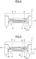
- the figures 1 to 7 show part of a rear axle 10 of a motor vehicle.
- the rear axle part 10 comprises a body 12, which cannot be dismantled, a rear axle 14 connecting two wheels 16, 18, a train bar 20 or connecting rod comprising a first end 20a rotatably mounted on the axle 14 and a second end 20b rotatably mounted on a safety member 22 fixed to the body 12.
- the train bar 20 may be a bar of the “Panhard” type, consisting of a rigid metal rod allowing the connection between one end of the axle and the body and allowing lateral guidance of the rear axle.
- the train bar 20 works in compression for shocks to the wheel located on the side where said bar is attached to the axle (located on the left in the figures) and in traction for shocks to the wheel located on the side where said bar is. attached to the body (located on the right in the figures).
- the rear axle part 10 also comprises a reinforcing bar 24 mounted in series with the axle bar 20 and comprising a first end 24a rotatably mounted on the body 12, on the side where the undercarriage bar is fixed to the axle, and a second end 24b rotatably mounted on the undercarriage bar 20 and on the safety member 22, on the side where the undercarriage bar is fixed to the body.
- the reinforcement bar 24 is fixed so as to work in the opposite direction relative to the train bar. In other words, when the train bar 20 works in tension, the reinforcement bar 24 works in compression and vice versa.
- Such a reinforcement bar 24 between the body 12 and the opposite side of the base structure makes it possible to repel part of the tensile forces in the event of a side impact.
- such a reinforcement bar does not make it possible to absorb all the energy of the side impact.
- the reinforcement bar 24 has, for example, a U-shaped section, comprising two coaxial bores (not shown) for receiving an axis 26.
- the reinforcement bar 24 is mounted for rotation on said axis 26.
- the end 20b of the undercarriage bar 20 is mounted within the U-shape of said reinforcing bar and rotatably about said axis 26.
- the safety member 22 comprises a first end 22a rotatably mounted on the body 12 by a first pin 28 and a second end 22b rotatably mounted on the pin 26 on which are rotatably mounted the second ends 20b, 24b of the undercarriage bar 20 and of the reinforcement bar 24.
- the fixing point P1 of the undercarriage bar 20 and the fixing point P2 of the force take-up bar 24 on the safety member 22 are merged here.
- the safety member 22 here has the form of a connecting rod or rod articulated around two pivot links produced respectively by a screwed assembly or by bushings making it possible to ensure freedom of movement in the lateral direction of the lateral vehicle of the points of fixing P1, P2 common to the undercarriage bar 20 and the reinforcement bar 24 in the event of a side impact to the wheel.
- a traction force F T for example, in the event of a side impact, for example on a rear wheel on the side of the body illustrated on figure 2 , the rod 22 pivots by its end 22a fixed to the body around the axis 28, allowing the common fixing point P1, P2 to move angularly around said axis 28 causing movement in the lateral direction of the train bar 20 and of the reinforcement bar 24.
- the reinforcement bar 24 thus absorbs the energy of the side impact by buckling. Thanks to the link, the body 12 and the landing gear 20 are not damaged.
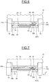
- the safety member 30, 40 is in the form of a deformable and ductile mechanical part, that is to say that it can be pulled, stretched without breaking.
- the safety member 30, 40 is configured to deform and move angularly with respect to its point of attachment to the body in the event of a side impact to the wheel without damage to the body.
- the safety member 30 or deformable yoke has an L-shape comprising a first part 32 fixed to the body 12 for example by screws and a second part 34 forming an angle between 45 ° and 90 ° relative to the first part 32 and extending towards the axle 14.
- the end 34a of the second part 34 of the deformable yoke 30 comprises a bore (not referenced) for receiving the axle 26 on which the train bar is rotatably mounted 20 and the reinforcing bar 24.
- the axis 26 may be in the form of a screw.
- the second part 34 of the deformable yoke 30 pivots by its end fixed to the first part 32, allowing the common fixing point P1, P2 to move angularly around the same axis causing the displacement in the lateral direction of the train bar 20 and of the reinforcement bar 24.
- the bar reinforcement 24 thus absorbs the energy of the side impact by buckling. Thanks to the deformable yoke, the body 12 and the undercarriage 20 are not damaged.
- the train bar 20 absorbs the forces by buckling.
- the reinforcing bar 24 and the deformable yoke 30 do not move and the body 12 is thus preserved.
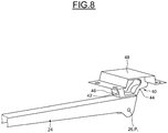
- the safety member 40 or deformable yoke is part of the reinforcing bar 24.
- the safety member 40 comprises a lower part 42 fixed to the reinforcing bar 24, for example, by welding, two side flanks 44, 46 extending towards the body 12 and an upper part 48 fixed respectively to the upper ends of the lateral sides, for example by welding, and to the body, for example by screw means.
- the safety member is made from stamped metal sheets and machined to remove material to allow it to be ductile, that is to say to deform without breaking during a side impact at the wheel.
- the train bar 20 is fixed to the assembly comprising the reinforcing bar 24 and the deformable yoke 40.
- a traction force F T for example, in the event of a side impact, for example on a rear wheel on the side of the body illustrated on figure 7 , the lateral flanks 44, 46 of the deformable yoke 40 are deformed allowing the fixing point P1 of the landing gear bar 20 to move angularly causing the displacement in the lateral direction of the gear bar 20.
- the reinforcement bar assembly 24 / deformable yoke 40 thus absorb the energy of the side impact by buckling and deformation respectively. Thanks to the deformable yoke, the body 12 and the undercarriage 20 are not damaged.
- the train bar 20 absorbs the forces by buckling.
- the reinforcing bar 24 and the deformable yoke 40 do not move and the body 12 is thus preserved.
- the safety member 22, 30, 40 and the reinforcing bar 24 are respectively fixed to the body by screws, bushings or ball joints, or any other means allowing these parts to be interchangeable and thus limit repair costs.
- the safety member 22, 30, 40 is made of a highly ductile material, such as, for example, steel, aluminum with a high elongation at break or any other material allowing to obtain strong deformations without risk of breakage, in particular for safety reasons.
- the safety member 22, 30, 40 is for example made of HE450M steel.
- the safety member acts as a fusible part when the energy of a side impact is transmitted to a rear wheel of the motor vehicle. Its deformation, as well as the deformation of the reinforcement bar, make it possible to generate a noise nuisance alerting the driver of the vehicle that a side impact damaging the wheel has occurred.
Landscapes
- Engineering & Computer Science (AREA)
- Mechanical Engineering (AREA)
- Vibration Dampers (AREA)
- Vehicle Body Suspensions (AREA)
- Body Structure For Vehicles (AREA)
Claims (10)
- Kraftfahrzeughinterachse, umfassend einen Aufbau (12), eine hintere Radachse (14), die zwei Räder (16, 18) verbindet, und eine Achsstrebe (20), die ein erstes Ende (20a) umfasst, das drehbar an der Radachse montiert ist, dadurch gekennzeichnet, dass sie ein Sicherheitsglied (22, 30, 40) umfasst, das jeweils an dem Aufbau (12) des Fahrzeugs und an einem zweiten Ende (20b) der Achsstrebe befestigt ist, wobei das Sicherheitsglied dazu ausgestaltet ist, bei einem Aufprall an dem Rad, das an der Seite, an der die Achsstrebe (20) an dem Glied befestigt ist, angeordnet ist, die winkelförmige Bewegung des Befestigungspunkts (P1) der Strebe bezüglich des Glieds zu gestatten.
- Hinterachse nach Anspruch 1, umfassend eine Verstärkungsstrebe (24), die ein erstes Ende (24a), das an der Seite drehbar an dem Aufbau (12) montiert ist, an der die Achsstrebe (20) an der Radachse (14) befestigt ist, und ein an dem Sicherheitsglied (22, 30, 40) befestigtes zweites Ende (24b) aufweist.
- Hinterachse nach Anspruch 2, wobei die Verstärkungsstrebe (24) einen U-förmigen Querschnitt aufweist, der zwei koaxiale Bohrungen zur Aufnahme eines Bolzens (26) umfasst, wobei die Verstärkungsstrebe (24) und die Achsstrebe (20) um den Bolzen (26) drehbar montiert sind.
- Hinterachse nach Anspruch 3, wobei das Sicherheitsglied (22, 30) ein erstes Ende (22a, 30a), das an dem Aufbau (12) befestigt ist, und ein zweites Ende (22b, 30b), das den Bolzen (26) aufnimmt, umfasst.
- Hinterachse nach einem der vorhergehenden Ansprüche, wobei das Sicherheitsglied (22) die Form einer um zwei Drehzapfverbindungen angelenkten Schwinge hat, wodurch eine Bewegungsfreiheit in der seitlichen Richtung des Fahrzeugs des der Achsstrebe (20) und der Verstärkungsstrebe (24) gemeinsamen Befestigungspunkts (P1, P2) bei einem Aufprall an dem Rad sichergestellt werden kann, das an der Seite, an der die Strebe an dem Glied befestigt ist, angeordnet ist.
- Hinterachse nach einem der vorhergehenden Ansprüche, wobei das Sicherheitsglied (30, 40) ein deformierbares und duktiles mechanisches Teil ist, das dazu ausgestaltet ist, sich bei einem seitlichen Aufprall an dem Rad zu deformieren und sich winkelmäßig bezüglich seines Befestigungspunkts an dem Aufbau (12) zu bewegen.
- Hinterachse nach Anspruch 6, wobei das Sicherheitsglied (30) eine L-Form hat, die einen ersten Teil (32), der an dem Aufbau (12) befestigt ist, und einen zweiten Teil (34) umfasst, der bezüglich des ersten Teils (32) einen Winkel zwischen 45° und 90° bildet und sich zu der Radachse (14) hin erstreckt.
- Hinterachse nach Anspruch 6, wobei das Sicherheitsglied (40) Teil der Verstärkungsstrebe (24) ist.
- Hinterachse nach Anspruch 8, wobei das Sicherheitsglied (40) einen unteren Teil (42), der an der Verstärkungsstrebe (24) befestigt ist, zwei seitliche Flanken (44, 46), die sich zu dem Aufbau (12) hin erstrecken, und einen oberen Teil (48) umfasst, der jeweils an den oberen Enden der seitlichen Flanken und an dem Aufbau befestigt ist.
- Kraftfahrzeug, umfassend einen Aufbau (12), eine Hinterachse (10) nach einem der vorhergehenden Ansprüche.
Applications Claiming Priority (1)
| Application Number | Priority Date | Filing Date | Title |
|---|---|---|---|
| FR1756287A FR3068669B1 (fr) | 2017-07-04 | 2017-07-04 | Train arriere de vehicule automobile comprenant des moyens d'absorption de l'energie d'un choc lateral |
Publications (2)
| Publication Number | Publication Date |
|---|---|
| EP3424757A1 EP3424757A1 (de) | 2019-01-09 |
| EP3424757B1 true EP3424757B1 (de) | 2021-02-17 |
Family
ID=59699925
Family Applications (1)
| Application Number | Title | Priority Date | Filing Date |
|---|---|---|---|
| EP18181255.3A Active EP3424757B1 (de) | 2017-07-04 | 2018-07-02 | Hinterachse eines kraftfahrzeugs, die energieabsorptionsmittel eines seitlichen aufpralls umfasst |
Country Status (2)
| Country | Link |
|---|---|
| EP (1) | EP3424757B1 (de) |
| FR (1) | FR3068669B1 (de) |
Family Cites Families (4)
| Publication number | Priority date | Publication date | Assignee | Title |
|---|---|---|---|---|
| JPH0379410A (ja) * | 1989-08-23 | 1991-04-04 | Nissan Motor Co Ltd | 車軸式懸架装置 |
| JPH11165518A (ja) * | 1997-12-05 | 1999-06-22 | Nissan Motor Co Ltd | リヤサスペンションのリンク取付け構造 |
| JP3716610B2 (ja) * | 1998-03-30 | 2005-11-16 | マツダ株式会社 | 自動車の後輪懸架装置 |
| CN104442272B (zh) * | 2014-11-21 | 2017-11-03 | 重庆永淳新能源科技有限公司 | 电动汽车防侧撞后桥结构 |
-
2017
- 2017-07-04 FR FR1756287A patent/FR3068669B1/fr active Active
-
2018
- 2018-07-02 EP EP18181255.3A patent/EP3424757B1/de active Active
Non-Patent Citations (1)
| Title |
|---|
| None * |
Also Published As
| Publication number | Publication date |
|---|---|
| EP3424757A1 (de) | 2019-01-09 |
| FR3068669A1 (fr) | 2019-01-11 |
| FR3068669B1 (fr) | 2019-11-22 |
Similar Documents
| Publication | Publication Date | Title |
|---|---|---|
| EP0802100B1 (de) | Schienenfahrzeug mit einem Fahrerstand, der eine energieaufnehmende Struktur mit progressiver Verformung aufweist | |
| CA2121995C (fr) | Dispositif d'amortissement de choc | |
| EP2934953A1 (de) | Stossdämpfungsvorrichtung für die vorder- oder hinterstruktur eines fahrzeugs | |
| EP3412506B1 (de) | Optischer block für kraftfahrzeug | |
| EP3424757B1 (de) | Hinterachse eines kraftfahrzeugs, die energieabsorptionsmittel eines seitlichen aufpralls umfasst | |
| FR2879549A1 (fr) | Dispositif absorbeur de chocs pour vehicule ferroviaire | |
| EP1106467A1 (de) | Vorrichtung zur kontrollierten Verformung durch Krafteinwirkung oder zur Aufnahme von Energie durch Verformung, insbesondere Hindernisabweiser für ein Schienenfahrzeug | |
| FR3092067A1 (fr) | Berceau moteur pour véhicule automobile et véhicule comportant un tel berceau | |
| EP3085554B1 (de) | Stossdämpfereinheit, die eine abschleppbuchse umfasst, und fahrzeug, das eine solche stossdämpfereinheit umfasst | |
| EP2130717B1 (de) | System zur Begrenzung von Schäden im Fall von Aufprall, die von einem Sichtelement oder zumindest einem Organ eines Kraftfahrzeugs erzeugt werden könnten | |
| EP3427981B1 (de) | Hinterachse eines kraftfahrzeugs, die energieabsorptionsmittel eines rückwärtigen aufpralls umfasst | |
| FR3093674A1 (fr) | Train de véhicule automobile comportant un bras de suspension assemblé comportant un organe de sureté fusible | |
| FR3055583B1 (fr) | Train arriere de vehicule automobile comprenant des moyens d'absorption de l'energie d'un choc lateral | |
| EP3362334A1 (de) | Kraftfahrzeugbauteil und vorderer unterer abschnitt mit solch einem teil | |
| EP3027442B1 (de) | Antriebsstrang für ein kraftfahrzeug | |
| FR3071808B1 (fr) | Pied avant renforce de vehicule | |
| FR3159366A1 (fr) | Dispositif d’absorption de chocs renforcé en traction. | |
| WO2019043309A1 (fr) | Vehicule comportant un train arriere a deplacement longitudinal controle en cas de choc arriere | |
| FR3137649A1 (fr) | Structure avant de véhicule automobile et véhicule automobile comportant une telle structure avant | |
| FR2982814A1 (fr) | Systeme de resistance aux chocs comprenant une piece de renfort. | |
| WO2010010276A2 (fr) | Element de carrosserie avec moyens de limitation du recul de cet element lors d'un choc sur celui-ci | |
| EP4093652A1 (de) | Kraftfahrzeug mit mittel zum lösen des vorderrades bei frontalaufprall | |
| EP1250538A1 (de) | Sicherung eines elastischen gelenkes | |
| EP1874592A2 (de) | Frontstruktur für ein kraftfahrzeug | |
| EP3027448A1 (de) | Fronteinheit für ein motorfahrzeug |
Legal Events
| Date | Code | Title | Description |
|---|---|---|---|
| PUAI | Public reference made under article 153(3) epc to a published international application that has entered the european phase |
Free format text: ORIGINAL CODE: 0009012 |
|
| STAA | Information on the status of an ep patent application or granted ep patent |
Free format text: STATUS: THE APPLICATION HAS BEEN PUBLISHED |
|
| AK | Designated contracting states |
Kind code of ref document: A1 Designated state(s): AL AT BE BG CH CY CZ DE DK EE ES FI FR GB GR HR HU IE IS IT LI LT LU LV MC MK MT NL NO PL PT RO RS SE SI SK SM TR |
|
| AX | Request for extension of the european patent |
Extension state: BA ME |
|
| STAA | Information on the status of an ep patent application or granted ep patent |
Free format text: STATUS: REQUEST FOR EXAMINATION WAS MADE |
|
| 17P | Request for examination filed |
Effective date: 20190625 |
|
| RBV | Designated contracting states (corrected) |
Designated state(s): AL AT BE BG CH CY CZ DE DK EE ES FI FR GB GR HR HU IE IS IT LI LT LU LV MC MK MT NL NO PL PT RO RS SE SI SK SM TR |
|
| GRAP | Despatch of communication of intention to grant a patent |
Free format text: ORIGINAL CODE: EPIDOSNIGR1 |
|
| STAA | Information on the status of an ep patent application or granted ep patent |
Free format text: STATUS: GRANT OF PATENT IS INTENDED |
|
| INTG | Intention to grant announced |
Effective date: 20200603 |
|
| GRAS | Grant fee paid |
Free format text: ORIGINAL CODE: EPIDOSNIGR3 |
|
| GRAA | (expected) grant |
Free format text: ORIGINAL CODE: 0009210 |
|
| STAA | Information on the status of an ep patent application or granted ep patent |
Free format text: STATUS: THE PATENT HAS BEEN GRANTED |
|
| AK | Designated contracting states |
Kind code of ref document: B1 Designated state(s): AL AT BE BG CH CY CZ DE DK EE ES FI FR GB GR HR HU IE IS IT LI LT LU LV MC MK MT NL NO PL PT RO RS SE SI SK SM TR |
|
| REG | Reference to a national code |
Ref country code: GB Ref legal event code: FG4D Free format text: NOT ENGLISH |
|
| REG | Reference to a national code |
Ref country code: CH Ref legal event code: EP |
|
| REG | Reference to a national code |
Ref country code: DE Ref legal event code: R096 Ref document number: 602018012534 Country of ref document: DE |
|
| REG | Reference to a national code |
Ref country code: AT Ref legal event code: REF Ref document number: 1361017 Country of ref document: AT Kind code of ref document: T Effective date: 20210315 |
|
| REG | Reference to a national code |
Ref country code: IE Ref legal event code: FG4D Free format text: LANGUAGE OF EP DOCUMENT: FRENCH |
|
| REG | Reference to a national code |
Ref country code: LT Ref legal event code: MG9D |
|
| REG | Reference to a national code |
Ref country code: NL Ref legal event code: MP Effective date: 20210217 |
|
| PG25 | Lapsed in a contracting state [announced via postgrant information from national office to epo] |
Ref country code: FI Free format text: LAPSE BECAUSE OF FAILURE TO SUBMIT A TRANSLATION OF THE DESCRIPTION OR TO PAY THE FEE WITHIN THE PRESCRIBED TIME-LIMIT Effective date: 20210217 Ref country code: GR Free format text: LAPSE BECAUSE OF FAILURE TO SUBMIT A TRANSLATION OF THE DESCRIPTION OR TO PAY THE FEE WITHIN THE PRESCRIBED TIME-LIMIT Effective date: 20210518 Ref country code: HR Free format text: LAPSE BECAUSE OF FAILURE TO SUBMIT A TRANSLATION OF THE DESCRIPTION OR TO PAY THE FEE WITHIN THE PRESCRIBED TIME-LIMIT Effective date: 20210217 Ref country code: BG Free format text: LAPSE BECAUSE OF FAILURE TO SUBMIT A TRANSLATION OF THE DESCRIPTION OR TO PAY THE FEE WITHIN THE PRESCRIBED TIME-LIMIT Effective date: 20210517 Ref country code: NO Free format text: LAPSE BECAUSE OF FAILURE TO SUBMIT A TRANSLATION OF THE DESCRIPTION OR TO PAY THE FEE WITHIN THE PRESCRIBED TIME-LIMIT Effective date: 20210517 Ref country code: PT Free format text: LAPSE BECAUSE OF FAILURE TO SUBMIT A TRANSLATION OF THE DESCRIPTION OR TO PAY THE FEE WITHIN THE PRESCRIBED TIME-LIMIT Effective date: 20210617 Ref country code: LT Free format text: LAPSE BECAUSE OF FAILURE TO SUBMIT A TRANSLATION OF THE DESCRIPTION OR TO PAY THE FEE WITHIN THE PRESCRIBED TIME-LIMIT Effective date: 20210217 |
|
| REG | Reference to a national code |
Ref country code: AT Ref legal event code: MK05 Ref document number: 1361017 Country of ref document: AT Kind code of ref document: T Effective date: 20210217 |
|
| PG25 | Lapsed in a contracting state [announced via postgrant information from national office to epo] |
Ref country code: NL Free format text: LAPSE BECAUSE OF FAILURE TO SUBMIT A TRANSLATION OF THE DESCRIPTION OR TO PAY THE FEE WITHIN THE PRESCRIBED TIME-LIMIT Effective date: 20210217 Ref country code: PL Free format text: LAPSE BECAUSE OF FAILURE TO SUBMIT A TRANSLATION OF THE DESCRIPTION OR TO PAY THE FEE WITHIN THE PRESCRIBED TIME-LIMIT Effective date: 20210217 Ref country code: LV Free format text: LAPSE BECAUSE OF FAILURE TO SUBMIT A TRANSLATION OF THE DESCRIPTION OR TO PAY THE FEE WITHIN THE PRESCRIBED TIME-LIMIT Effective date: 20210217 Ref country code: RS Free format text: LAPSE BECAUSE OF FAILURE TO SUBMIT A TRANSLATION OF THE DESCRIPTION OR TO PAY THE FEE WITHIN THE PRESCRIBED TIME-LIMIT Effective date: 20210217 Ref country code: SE Free format text: LAPSE BECAUSE OF FAILURE TO SUBMIT A TRANSLATION OF THE DESCRIPTION OR TO PAY THE FEE WITHIN THE PRESCRIBED TIME-LIMIT Effective date: 20210217 |
|
| PG25 | Lapsed in a contracting state [announced via postgrant information from national office to epo] |
Ref country code: IS Free format text: LAPSE BECAUSE OF FAILURE TO SUBMIT A TRANSLATION OF THE DESCRIPTION OR TO PAY THE FEE WITHIN THE PRESCRIBED TIME-LIMIT Effective date: 20210617 |
|
| PG25 | Lapsed in a contracting state [announced via postgrant information from national office to epo] |
Ref country code: EE Free format text: LAPSE BECAUSE OF FAILURE TO SUBMIT A TRANSLATION OF THE DESCRIPTION OR TO PAY THE FEE WITHIN THE PRESCRIBED TIME-LIMIT Effective date: 20210217 Ref country code: CZ Free format text: LAPSE BECAUSE OF FAILURE TO SUBMIT A TRANSLATION OF THE DESCRIPTION OR TO PAY THE FEE WITHIN THE PRESCRIBED TIME-LIMIT Effective date: 20210217 Ref country code: AT Free format text: LAPSE BECAUSE OF FAILURE TO SUBMIT A TRANSLATION OF THE DESCRIPTION OR TO PAY THE FEE WITHIN THE PRESCRIBED TIME-LIMIT Effective date: 20210217 Ref country code: SM Free format text: LAPSE BECAUSE OF FAILURE TO SUBMIT A TRANSLATION OF THE DESCRIPTION OR TO PAY THE FEE WITHIN THE PRESCRIBED TIME-LIMIT Effective date: 20210217 |
|
| REG | Reference to a national code |
Ref country code: DE Ref legal event code: R097 Ref document number: 602018012534 Country of ref document: DE |
|
| PG25 | Lapsed in a contracting state [announced via postgrant information from national office to epo] |
Ref country code: RO Free format text: LAPSE BECAUSE OF FAILURE TO SUBMIT A TRANSLATION OF THE DESCRIPTION OR TO PAY THE FEE WITHIN THE PRESCRIBED TIME-LIMIT Effective date: 20210217 Ref country code: DK Free format text: LAPSE BECAUSE OF FAILURE TO SUBMIT A TRANSLATION OF THE DESCRIPTION OR TO PAY THE FEE WITHIN THE PRESCRIBED TIME-LIMIT Effective date: 20210217 Ref country code: SK Free format text: LAPSE BECAUSE OF FAILURE TO SUBMIT A TRANSLATION OF THE DESCRIPTION OR TO PAY THE FEE WITHIN THE PRESCRIBED TIME-LIMIT Effective date: 20210217 |
|
| PLBE | No opposition filed within time limit |
Free format text: ORIGINAL CODE: 0009261 |
|
| STAA | Information on the status of an ep patent application or granted ep patent |
Free format text: STATUS: NO OPPOSITION FILED WITHIN TIME LIMIT |
|
| 26N | No opposition filed |
Effective date: 20211118 |
|
| PG25 | Lapsed in a contracting state [announced via postgrant information from national office to epo] |
Ref country code: AL Free format text: LAPSE BECAUSE OF FAILURE TO SUBMIT A TRANSLATION OF THE DESCRIPTION OR TO PAY THE FEE WITHIN THE PRESCRIBED TIME-LIMIT Effective date: 20210217 Ref country code: ES Free format text: LAPSE BECAUSE OF FAILURE TO SUBMIT A TRANSLATION OF THE DESCRIPTION OR TO PAY THE FEE WITHIN THE PRESCRIBED TIME-LIMIT Effective date: 20210217 |
|
| PG25 | Lapsed in a contracting state [announced via postgrant information from national office to epo] |
Ref country code: SI Free format text: LAPSE BECAUSE OF FAILURE TO SUBMIT A TRANSLATION OF THE DESCRIPTION OR TO PAY THE FEE WITHIN THE PRESCRIBED TIME-LIMIT Effective date: 20210217 |
|
| REG | Reference to a national code |
Ref country code: CH Ref legal event code: PL |
|
| PG25 | Lapsed in a contracting state [announced via postgrant information from national office to epo] |
Ref country code: MC Free format text: LAPSE BECAUSE OF FAILURE TO SUBMIT A TRANSLATION OF THE DESCRIPTION OR TO PAY THE FEE WITHIN THE PRESCRIBED TIME-LIMIT Effective date: 20210217 |
|
| REG | Reference to a national code |
Ref country code: BE Ref legal event code: MM Effective date: 20210731 |
|
| PG25 | Lapsed in a contracting state [announced via postgrant information from national office to epo] |
Ref country code: LI Free format text: LAPSE BECAUSE OF NON-PAYMENT OF DUE FEES Effective date: 20210731 Ref country code: IT Free format text: LAPSE BECAUSE OF FAILURE TO SUBMIT A TRANSLATION OF THE DESCRIPTION OR TO PAY THE FEE WITHIN THE PRESCRIBED TIME-LIMIT Effective date: 20210217 Ref country code: CH Free format text: LAPSE BECAUSE OF NON-PAYMENT OF DUE FEES Effective date: 20210731 |
|
| PG25 | Lapsed in a contracting state [announced via postgrant information from national office to epo] |
Ref country code: IS Free format text: LAPSE BECAUSE OF FAILURE TO SUBMIT A TRANSLATION OF THE DESCRIPTION OR TO PAY THE FEE WITHIN THE PRESCRIBED TIME-LIMIT Effective date: 20210617 Ref country code: LU Free format text: LAPSE BECAUSE OF NON-PAYMENT OF DUE FEES Effective date: 20210702 |
|
| PG25 | Lapsed in a contracting state [announced via postgrant information from national office to epo] |
Ref country code: IE Free format text: LAPSE BECAUSE OF NON-PAYMENT OF DUE FEES Effective date: 20210702 Ref country code: BE Free format text: LAPSE BECAUSE OF NON-PAYMENT OF DUE FEES Effective date: 20210731 |
|
| PG25 | Lapsed in a contracting state [announced via postgrant information from national office to epo] |
Ref country code: CY Free format text: LAPSE BECAUSE OF FAILURE TO SUBMIT A TRANSLATION OF THE DESCRIPTION OR TO PAY THE FEE WITHIN THE PRESCRIBED TIME-LIMIT Effective date: 20210217 |
|
| P01 | Opt-out of the competence of the unified patent court (upc) registered |
Effective date: 20230608 |
|
| PG25 | Lapsed in a contracting state [announced via postgrant information from national office to epo] |
Ref country code: HU Free format text: LAPSE BECAUSE OF FAILURE TO SUBMIT A TRANSLATION OF THE DESCRIPTION OR TO PAY THE FEE WITHIN THE PRESCRIBED TIME-LIMIT; INVALID AB INITIO Effective date: 20180702 |
|
| PG25 | Lapsed in a contracting state [announced via postgrant information from national office to epo] |
Ref country code: MK Free format text: LAPSE BECAUSE OF FAILURE TO SUBMIT A TRANSLATION OF THE DESCRIPTION OR TO PAY THE FEE WITHIN THE PRESCRIBED TIME-LIMIT Effective date: 20210217 |
|
| PG25 | Lapsed in a contracting state [announced via postgrant information from national office to epo] |
Ref country code: TR Free format text: LAPSE BECAUSE OF FAILURE TO SUBMIT A TRANSLATION OF THE DESCRIPTION OR TO PAY THE FEE WITHIN THE PRESCRIBED TIME-LIMIT Effective date: 20210217 |
|
| PG25 | Lapsed in a contracting state [announced via postgrant information from national office to epo] |
Ref country code: MT Free format text: LAPSE BECAUSE OF FAILURE TO SUBMIT A TRANSLATION OF THE DESCRIPTION OR TO PAY THE FEE WITHIN THE PRESCRIBED TIME-LIMIT Effective date: 20210217 |
|
| PGFP | Annual fee paid to national office [announced via postgrant information from national office to epo] |
Ref country code: DE Payment date: 20250722 Year of fee payment: 8 |
|
| PGFP | Annual fee paid to national office [announced via postgrant information from national office to epo] |
Ref country code: GB Payment date: 20250722 Year of fee payment: 8 |
|
| PGFP | Annual fee paid to national office [announced via postgrant information from national office to epo] |
Ref country code: FR Payment date: 20250725 Year of fee payment: 8 |