EP0802076A2 - Méthode d'opération d'un appareil de chauffage ou de climatisation - Google Patents
Méthode d'opération d'un appareil de chauffage ou de climatisation Download PDFInfo
- Publication number
- EP0802076A2 EP0802076A2 EP97102188A EP97102188A EP0802076A2 EP 0802076 A2 EP0802076 A2 EP 0802076A2 EP 97102188 A EP97102188 A EP 97102188A EP 97102188 A EP97102188 A EP 97102188A EP 0802076 A2 EP0802076 A2 EP 0802076A2
- Authority
- EP
- European Patent Office
- Prior art keywords
- temperature
- outflow
- section
- temperature control
- air
- Prior art date
- Legal status (The legal status is an assumption and is not a legal conclusion. Google has not performed a legal analysis and makes no representation as to the accuracy of the status listed.)
- Withdrawn
Links
Images
Classifications
-
- G—PHYSICS
- G05—CONTROLLING; REGULATING
- G05D—SYSTEMS FOR CONTROLLING OR REGULATING NON-ELECTRIC VARIABLES
- G05D23/00—Control of temperature
- G05D23/01—Control of temperature without auxiliary power
- G05D23/12—Control of temperature without auxiliary power with sensing element responsive to pressure or volume changes in a confined fluid
-
- B—PERFORMING OPERATIONS; TRANSPORTING
- B60—VEHICLES IN GENERAL
- B60H—ARRANGEMENTS OF HEATING, COOLING, VENTILATING OR OTHER AIR-TREATING DEVICES SPECIALLY ADAPTED FOR PASSENGER OR GOODS SPACES OF VEHICLES
- B60H1/00—Heating, cooling or ventilating [HVAC] devices
- B60H1/00642—Control systems or circuits; Control members or indication devices for heating, cooling or ventilating devices
- B60H1/00814—Control systems or circuits characterised by their output, for controlling particular components of the heating, cooling or ventilating installation
- B60H1/00821—Control systems or circuits characterised by their output, for controlling particular components of the heating, cooling or ventilating installation the components being ventilating, air admitting or air distributing devices
- B60H1/00864—Ventilators and damper doors
-
- F—MECHANICAL ENGINEERING; LIGHTING; HEATING; WEAPONS; BLASTING
- F24—HEATING; RANGES; VENTILATING
- F24F—AIR-CONDITIONING; AIR-HUMIDIFICATION; VENTILATION; USE OF AIR CURRENTS FOR SCREENING
- F24F11/00—Control or safety arrangements
- F24F11/30—Control or safety arrangements for purposes related to the operation of the system, e.g. for safety or monitoring
-
- F—MECHANICAL ENGINEERING; LIGHTING; HEATING; WEAPONS; BLASTING
- F24—HEATING; RANGES; VENTILATING
- F24F—AIR-CONDITIONING; AIR-HUMIDIFICATION; VENTILATION; USE OF AIR CURRENTS FOR SCREENING
- F24F11/00—Control or safety arrangements
- F24F11/70—Control systems characterised by their outputs; Constructional details thereof
- F24F11/72—Control systems characterised by their outputs; Constructional details thereof for controlling the supply of treated air, e.g. its pressure
- F24F11/74—Control systems characterised by their outputs; Constructional details thereof for controlling the supply of treated air, e.g. its pressure for controlling air flow rate or air velocity
- F24F11/75—Control systems characterised by their outputs; Constructional details thereof for controlling the supply of treated air, e.g. its pressure for controlling air flow rate or air velocity for maintaining constant air flow rate or air velocity
-
- F—MECHANICAL ENGINEERING; LIGHTING; HEATING; WEAPONS; BLASTING
- F24—HEATING; RANGES; VENTILATING
- F24F—AIR-CONDITIONING; AIR-HUMIDIFICATION; VENTILATION; USE OF AIR CURRENTS FOR SCREENING
- F24F11/00—Control or safety arrangements
- F24F11/70—Control systems characterised by their outputs; Constructional details thereof
- F24F11/72—Control systems characterised by their outputs; Constructional details thereof for controlling the supply of treated air, e.g. its pressure
- F24F11/74—Control systems characterised by their outputs; Constructional details thereof for controlling the supply of treated air, e.g. its pressure for controlling air flow rate or air velocity
- F24F11/77—Control systems characterised by their outputs; Constructional details thereof for controlling the supply of treated air, e.g. its pressure for controlling air flow rate or air velocity by controlling the speed of ventilators
-
- Y—GENERAL TAGGING OF NEW TECHNOLOGICAL DEVELOPMENTS; GENERAL TAGGING OF CROSS-SECTIONAL TECHNOLOGIES SPANNING OVER SEVERAL SECTIONS OF THE IPC; TECHNICAL SUBJECTS COVERED BY FORMER USPC CROSS-REFERENCE ART COLLECTIONS [XRACs] AND DIGESTS
- Y02—TECHNOLOGIES OR APPLICATIONS FOR MITIGATION OR ADAPTATION AGAINST CLIMATE CHANGE
- Y02B—CLIMATE CHANGE MITIGATION TECHNOLOGIES RELATED TO BUILDINGS, e.g. HOUSING, HOUSE APPLIANCES OR RELATED END-USER APPLICATIONS
- Y02B30/00—Energy efficient heating, ventilation or air conditioning [HVAC]
- Y02B30/70—Efficient control or regulation technologies, e.g. for control of refrigerant flow, motor or heating
-
- Y—GENERAL TAGGING OF NEW TECHNOLOGICAL DEVELOPMENTS; GENERAL TAGGING OF CROSS-SECTIONAL TECHNOLOGIES SPANNING OVER SEVERAL SECTIONS OF THE IPC; TECHNICAL SUBJECTS COVERED BY FORMER USPC CROSS-REFERENCE ART COLLECTIONS [XRACs] AND DIGESTS
- Y10—TECHNICAL SUBJECTS COVERED BY FORMER USPC
- Y10S—TECHNICAL SUBJECTS COVERED BY FORMER USPC CROSS-REFERENCE ART COLLECTIONS [XRACs] AND DIGESTS
- Y10S236/00—Automatic temperature and humidity regulation
- Y10S236/09—Fan control
Definitions
- the invention relates to a method for operating a heating and / or air conditioning system according to the preamble of claim 1.
- Such methods are used, for example, for operating heating and / or air conditioning systems installed in motor vehicles, air being used as the temperature control fluid and actuators for regulating the outflow cross-section of the one or more air outflow flaps are used, through the adjustment of which the air mass flow blown out into the vehicle interior and thus the heating or air-conditioning output for the vehicle interior can be set as desired.
- a method of this type for air conditioning a vehicle interior is known from the published patent application DE 43 41 208 A1, in which the actual temperature used for interior temperature control is measured in the outlet area of the air flow from the vehicle interior and the entry temperature of the air flow into the vehicle interior is also recorded and the air mass flow then, if the interior temperature control difference exceeds a predetermined value, it is adjusted so that the mathematical product of a key figure for the air mass flow and the difference between the inlet temperature and the actual temperature becomes maximum.
- the published patent application DE 41 13 374 A1 describes a control device for an air conditioning system with a fan for blowing air at a controlled temperature into a room and with a sensor device for measuring the skin temperature of the people in the room.
- the control device is provided with control means which determine the strength of the injected Determine the air flow as a function of the skin temperature measured by means of the sensor device and a target skin temperature in order to achieve an optimal target temperature sensation for the people.
- the electronic control means are designed to activate the fan, which blows in the air flow with the strength determined in this way.
- the air quantity to be supplied to the vehicle interior can be regulated as a function of a predefined setpoint, taking into account interfering influences, such as driving speed, window and sunroof actuations and the like.
- a device is provided for measuring the differential pressure between the inlet pressure prevailing in an air duct behind a delivery blower and the pressure prevailing in the vehicle interior, and the voltage applied to the blower motor is based on a comparison of the measured value carried out in an associated control unit, which is a measure of the amount of air conveyed Differential pressure depending on an adjustable predetermined target air volume.
- a control arrangement is also mentioned in this publication, in which a signal proportional to the driving speed is tapped on the speedometer, with which the position of an input flap in the air duct is regulated in order to adjust the air quantity supplied to the vehicle interior as a function of the driving speed.
- blower output is fixed depending on the control deviation of the interior temperature, the heating water supply temperature or cooling water temperature, the heating mode or cooling mode, the driving speed signal, the filter or recirculation mode, the sun exposure programmed fan speed base load level and / or from individual flap positions, eg increasing the fan speed by a fixed value when the footwell ventilation flaps are opened, reducing the speed when the skimmer flaps are open, etc.
- the air blow-out speed at which the air exits from the corresponding nozzles of a heating and / or air conditioning system of a motor vehicle into its interior mainly depends on the fan speed or the fan power, the constant intake cross-sectional area of the fan tract and the changing total discharge cross-section of the entire Heating or air conditioning.
- the fan runs at a certain power at a base load level. Due to the fully automatic adjustment of the flap positions depending on the temperature of the blown air, the overall outflow cross-section of the heating or air conditioning system and thus the air speed at the outflow nozzles usually change due to the design.
- the invention is based on the technical problem of providing a method of the type mentioned at the outset, with which a comfortable temperature control is ensured in a comparatively simple manner, in which changes in air speed due to automatic changes in the effective outflow cross section are counteracted.
- each actuator serving to regulate the outflow cross section is automatically controlled into a position which is selected as a function of the temperature of the blown-out temperature control fluid, for which purpose a corresponding characteristic curve is expediently used is specified. From the characteristics of the positions of the actuators involved, which are dependent on the temperature of the blow-out fluid and the resulting total outflow cross-section, a characteristic is determined depending on the temperature of the blown-out temperature control fluid, according to which the delivery rate of the delivery fan is regulated. The delivery rate is set so that the outflow speed of the temperature control fluid remains essentially constant regardless of the respective outflow temperature.
- a further developed method according to claim 2 is specially adapted to the conditions of heating and / or air conditioning systems which are installed in motor vehicles and contain an intake fan as a conveying fan and various flaps as regulating elements regulating the flow cross-section.
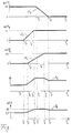
- the single figure shows, in diagram form, characteristic curves of various flaps of an air conditioning system of a motor vehicle and a characteristic curve of their total outflow cross section and the base load voltage of an intake blower, each as a function of the air outflow temperature.
- each air outflow channel can consist of several sub-channels, which lead to different areas of the vehicle interior and each contain its own flap.
- temperature control flap is understood below to mean the entirety of all actuators acting on the entire effective outflow cross section of the possibly multi-channel temperature control channel; the same applies analogously to the designations of defroster flap and footwell flap.
- characteristics of the flap angle ( ⁇ ) of the pivoting flaps are dependent on the temperature for the temperature flap, the defroster flap and the footwell flap the air flowing out of the air conditioning system and blown into the vehicle interior and serving as a temperature control fluid, as shown in the top three diagrams of the figure.
- the flap angle ( ⁇ T ) for the temperature flap decreases linearly as the air outflow temperature rises from a predetermined first temperature value (T 1 ) until it reaches zero at a second temperature value (T 2 ).
- the flap angle ( ⁇ E ) of the defroster flap increases linearly with increasing air outflow temperature (T L ) from a third temperature value (T 3 ) up to a maximum value of 44 °, which it achieves at a fourth temperature value (T 4 ) reached, which is smaller than the first temperature value (T 1 ).
- the flap angle ( ⁇ F ) of the footwell flap increases linearly from zero to a maximum value of 65 ° with increasing air outflow temperature (T L ) from a fifth temperature value (T 5 ) between the third (T 3 ) and the fourth (T 4 ) which is reached at a sixth temperature value (T 6 ) lying between the first (T 1 ) and the second (T 2 ).
- the control or regulating unit of the system now determines the resulting total outflow cross-section (A L ) of all air outflow channels of the system from the flap angle characteristic curves ( ⁇ T , ⁇ E , ⁇ F ) which are predetermined as a function of the air outflow temperature.
- the resulting characteristic of the total outflow cross section (A L ) as a function of the air outflow temperature (T L ) is shown in its qualitative course in the second bottom diagram of the figure.
- the total outflow cross section (A L ) with increasing air outflow temperature (T L ) from a value which is determined by the temperature control flap open at a low air outflow temperature, piece by piece from the third temperature value (T 3 ) to the sixth temperature value (T 6 ) increases linearly, namely between the fifth (T 5 ) and the fourth temperature value (T 4 ) with a greater gradient than between the third (T 3 ) and the fifth (T 5 ) or between the fourth (T 4 ) and the first temperature value (T 1 ).
- There is only a very slight increase between the first (T 1 ) and the sixth temperature value (T 6 ) since in this area the increasing opening of the footwell flap is almost compensated by the closing of the temperature flap. Since the temperature flap continues to close when the air outflow temperature (T L ) increases beyond the maximum opening angle through the footwell flap, the total outflow cross-section (A L ) drops again somewhat to the second temperature value (T 2 ).
- the base load voltage (U G ) of a delivery blower of the air conditioning system in the form of a suction blower is suitably regulated automatically in such a way that the air outflow speed is independent of the prevailing one Total outflow cross section (A L ) remains approximately constant.
- blower voltage characteristic curves for operating a heating and / or air conditioning system in accordance with the method can result, in each case To ensure that automatic changes in the effective outflow cross-section of the system, which result, for example, from flap adjustments, do not lead to a noticeably different air outflow speed at the respective outflow nozzles.
- the characteristic curve (U G ) used to adjust the base load delivery capacity of the blower as a function of the air outflow temperature (T L ) can alternatively be determined using the characteristic curve of the total outflow cross section (A L ) by means of a series of measurements, in which for a air flow temperature value or a respective total of set flap angles, the blower voltage is changed until a constant value for the air outflow speed is established.
- the method-based measure of keeping the air outflow speed constant can, if desired, also be restricted to a part of all air outflow ducts or flaps of the heating and / or air conditioning system, for example, when used in motor vehicles, to the outflow ducts which are particularly relevant for the passengers' sense of train, like the outflow channels assigned to the side ventilation nozzles.
Landscapes
- Engineering & Computer Science (AREA)
- Physics & Mathematics (AREA)
- Mechanical Engineering (AREA)
- General Physics & Mathematics (AREA)
- Automation & Control Theory (AREA)
- Chemical & Material Sciences (AREA)
- Combustion & Propulsion (AREA)
- General Engineering & Computer Science (AREA)
- Thermal Sciences (AREA)
- Air-Conditioning For Vehicles (AREA)
Applications Claiming Priority (2)
| Application Number | Priority Date | Filing Date | Title |
|---|---|---|---|
| DE19615239 | 1996-04-18 | ||
| DE19615239A DE19615239C1 (de) | 1996-04-18 | 1996-04-18 | Verfahren zum Betrieb einer Heizungs- und/oder Klimaanlage |
Publications (2)
| Publication Number | Publication Date |
|---|---|
| EP0802076A2 true EP0802076A2 (fr) | 1997-10-22 |
| EP0802076A3 EP0802076A3 (fr) | 1999-06-09 |
Family
ID=7791582
Family Applications (1)
| Application Number | Title | Priority Date | Filing Date |
|---|---|---|---|
| EP97102188A Withdrawn EP0802076A3 (fr) | 1996-04-18 | 1997-02-12 | Méthode d'opération d'un appareil de chauffage ou de climatisation |
Country Status (3)
| Country | Link |
|---|---|
| US (1) | US5813600A (fr) |
| EP (1) | EP0802076A3 (fr) |
| DE (1) | DE19615239C1 (fr) |
Cited By (1)
| Publication number | Priority date | Publication date | Assignee | Title |
|---|---|---|---|---|
| CN104764160A (zh) * | 2015-03-30 | 2015-07-08 | 广东美的制冷设备有限公司 | 空调器室内机的恒风量控制方法、装置及空调器室内机 |
Families Citing this family (15)
| Publication number | Priority date | Publication date | Assignee | Title |
|---|---|---|---|---|
| DE19829567A1 (de) * | 1998-07-02 | 2000-01-05 | Mannesmann Vdo Ag | Luftzuführungseinrichtung und Verfahren zur Regelung der Luftzuführung in einem Fahrzeug |
| IT1310766B1 (it) * | 1999-12-03 | 2002-02-22 | Fiat Auto Spa | Gruppo di alimentazione per l'immissione di aria all'interno di unabitacolo di un veicolo. |
| FR2841501B1 (fr) * | 2002-06-27 | 2005-11-18 | Renault Sa | Procede et dispositif de commande de debit d'un appareil de climatisation de vehicule |
| DE102004005678A1 (de) * | 2004-02-05 | 2005-09-01 | Bayerische Motoren Werke Ag | Lüftungs-, Heiz- und/oder Klimaanlage eines Kraftfahrzeuges mit einem elektronischen Steuergerät |
| US7681630B2 (en) * | 2004-12-07 | 2010-03-23 | Cnh America Llc | HVAC system for a work vehicle |
| US7415903B2 (en) * | 2006-12-22 | 2008-08-26 | Chrysler Llc | Method and system for an impact sled footwell intrusion test |
| US20080241606A1 (en) * | 2007-03-30 | 2008-10-02 | Gallagher Emerson R | Method and apparatus for humidifying a gas in fuel cell systems |
| JP2009001140A (ja) * | 2007-06-21 | 2009-01-08 | Komatsu Ltd | 空調装置 |
| DE102008031712A1 (de) * | 2008-07-04 | 2010-01-07 | Bayerische Motoren Werke Aktiengesellschaft | Fahrzeug-Heiz- und/oder Klimaanlage mit einer Heiz- und Klimaautomatik |
| DE102010041440A1 (de) * | 2010-09-27 | 2012-03-29 | Siemens Aktiengesellschaft | Fahrzeug mit einer mit Hilfe eines Kühlluftmassenstrms gekühlten Komponente |
| JP5980637B2 (ja) * | 2012-09-26 | 2016-08-31 | シャープ株式会社 | 空気調和機 |
| US10060642B2 (en) * | 2014-10-22 | 2018-08-28 | Honeywell International Inc. | Damper fault detection |
| KR101673762B1 (ko) * | 2015-04-28 | 2016-11-07 | 현대자동차주식회사 | 자동차용 공조장치의 토출 풍량 제어 시스템 및 방법 |
| US11029057B2 (en) * | 2016-05-31 | 2021-06-08 | Robert J. Mowris | Economizer controller calibration |
| CN117366784B (zh) * | 2023-12-07 | 2024-03-15 | 珠海格力电器股份有限公司 | 进风挡板装置的异常检测方法、装置、存储介质及空调 |
Citations (3)
| Publication number | Priority date | Publication date | Assignee | Title |
|---|---|---|---|---|
| DE4113374A1 (de) | 1990-04-24 | 1991-10-31 | Toyoda Chuo Kenkyusho Kk | Regelungseinrichtung fuer eine klimaanlage |
| DE4100817A1 (de) | 1991-01-14 | 1992-07-16 | Behr Gmbh & Co | Luftmengen-regelanordnung fuer kraftfahrzeuge |
| DE4341208A1 (de) | 1993-12-03 | 1995-06-08 | Bayerische Motoren Werke Ag | Verfahren zum Klimatisieren eines Fahrzeug-Innenraumes |
Family Cites Families (8)
| Publication number | Priority date | Publication date | Assignee | Title |
|---|---|---|---|---|
| JPS6061322A (ja) * | 1983-09-14 | 1985-04-09 | Nissan Shatai Co Ltd | 車両の自動空調装置 |
| US4748822A (en) * | 1986-12-04 | 1988-06-07 | Carrier Corporation | Speed control of a variable speed air conditioning system |
| JPH01208216A (ja) * | 1986-12-19 | 1989-08-22 | Asmo Co Ltd | 車両用空気調和装置 |
| JPH0224214A (ja) * | 1988-07-13 | 1990-01-26 | Hitachi Ltd | 自動車用空調機の制御装置 |
| JP2680391B2 (ja) * | 1988-12-28 | 1997-11-19 | 日産自動車株式会社 | 自動車用空気調和装置のヒータユニット |
| US5400963A (en) * | 1991-07-10 | 1995-03-28 | Naldec Corporation | Method and apparatus for controlling vehicle air conditioner |
| JP3161055B2 (ja) * | 1992-07-15 | 2001-04-25 | 株式会社デンソー | 車両用空調装置 |
| JP3533716B2 (ja) * | 1994-09-09 | 2004-05-31 | 株式会社デンソー | 車両用空調装置 |
-
1996
- 1996-04-18 DE DE19615239A patent/DE19615239C1/de not_active Expired - Fee Related
-
1997
- 1997-02-12 EP EP97102188A patent/EP0802076A3/fr not_active Withdrawn
- 1997-04-18 US US08/840,916 patent/US5813600A/en not_active Expired - Fee Related
Patent Citations (3)
| Publication number | Priority date | Publication date | Assignee | Title |
|---|---|---|---|---|
| DE4113374A1 (de) | 1990-04-24 | 1991-10-31 | Toyoda Chuo Kenkyusho Kk | Regelungseinrichtung fuer eine klimaanlage |
| DE4100817A1 (de) | 1991-01-14 | 1992-07-16 | Behr Gmbh & Co | Luftmengen-regelanordnung fuer kraftfahrzeuge |
| DE4341208A1 (de) | 1993-12-03 | 1995-06-08 | Bayerische Motoren Werke Ag | Verfahren zum Klimatisieren eines Fahrzeug-Innenraumes |
Cited By (2)
| Publication number | Priority date | Publication date | Assignee | Title |
|---|---|---|---|---|
| CN104764160A (zh) * | 2015-03-30 | 2015-07-08 | 广东美的制冷设备有限公司 | 空调器室内机的恒风量控制方法、装置及空调器室内机 |
| CN104764160B (zh) * | 2015-03-30 | 2017-06-16 | 广东美的制冷设备有限公司 | 空调器室内机的恒风量控制方法、装置及空调器室内机 |
Also Published As
| Publication number | Publication date |
|---|---|
| EP0802076A3 (fr) | 1999-06-09 |
| DE19615239C1 (de) | 1997-03-20 |
| US5813600A (en) | 1998-09-29 |
Similar Documents
| Publication | Publication Date | Title |
|---|---|---|
| EP0316545B1 (fr) | Système de climatisation | |
| DE19615239C1 (de) | Verfahren zum Betrieb einer Heizungs- und/oder Klimaanlage | |
| DE4119042C2 (de) | Regelungseinrichtung einer Klimaanlage für Fahrzeuge | |
| EP1708901A1 (fr) | Systeme de chauffage, de ventilation ou de climatisation | |
| DE3016679A1 (de) | Belueftungs-, heizungs- und/oder klimaanlage fuer kraftfahrzeuge | |
| DE4425697C2 (de) | Klimagerät | |
| EP0495201B1 (fr) | Dispositif de commande du débit d'air pour véhicules à moteur | |
| DE3928944C3 (de) | Klimaanlage für Fahrzeuge | |
| DE3343487C2 (fr) | ||
| DE19829567A1 (de) | Luftzuführungseinrichtung und Verfahren zur Regelung der Luftzuführung in einem Fahrzeug | |
| DE102014109925A1 (de) | Mehrzonen-Klimatisierungseinrichtung | |
| DE10036502C1 (de) | Klimaanlage für ein Fahrzeug | |
| DE19629280B4 (de) | Heizvorrichtung | |
| DE10235526A1 (de) | Verfahren zur Steuerung/Regelung einer Belüftungseinrichtung einer Heiz-und/oder Klimaanlage | |
| DE4013043A1 (de) | Verfahren und vorrichtung zur erzeugung unterschiedlich warmer teilstroeme mit nur einem waermetauscher | |
| EP0876930B1 (fr) | Dispositif de climatisation pour l'habitacle d'un véhicle | |
| EP0847887B1 (fr) | Dispositif de chauffage ou de climatisation à canaux multiples | |
| DE19742106A1 (de) | Vorrichtung zum Zuführen von Luft in den Innenraum eines Fahrzeuges | |
| DE2634713A1 (de) | Verfahren und vorrichtung zum beheizen und belueften des innenraums von omnibussen | |
| EP1187733B1 (fr) | Dispositif de regulation de la temperature a l'interieur d'un vehicule | |
| WO2005084973A1 (fr) | Dispositif de climatisation notamment destine a un vehicule | |
| DE3217825A1 (de) | Klimaanlage fuer ein luftgekuehltes kraftfahrzeug | |
| DE10036509C1 (de) | Luftauslass für in den Innenraum eines Fahrzeuges einströmende Luft | |
| DE102014012627B3 (de) | Verfahren zum Betreiben einer Fahrzeug-Klimaanlage | |
| EP0771276B1 (fr) | Conditionneur d'air, en particulier pour vehicule automobile, a reglage de la temperature de l'air insuffle |
Legal Events
| Date | Code | Title | Description |
|---|---|---|---|
| PUAI | Public reference made under article 153(3) epc to a published international application that has entered the european phase |
Free format text: ORIGINAL CODE: 0009012 |
|
| AK | Designated contracting states |
Kind code of ref document: A2 Designated state(s): ES FR GB IT SE |
|
| RAP1 | Party data changed (applicant data changed or rights of an application transferred) |
Owner name: DAIMLERCHRYSLER AG |
|
| PUAL | Search report despatched |
Free format text: ORIGINAL CODE: 0009013 |
|
| AK | Designated contracting states |
Kind code of ref document: A3 Designated state(s): ES FR GB IT SE |
|
| 17P | Request for examination filed |
Effective date: 19990514 |
|
| GRAG | Despatch of communication of intention to grant |
Free format text: ORIGINAL CODE: EPIDOS AGRA |
|
| 17Q | First examination report despatched |
Effective date: 20010418 |
|
| GRAG | Despatch of communication of intention to grant |
Free format text: ORIGINAL CODE: EPIDOS AGRA |
|
| GRAH | Despatch of communication of intention to grant a patent |
Free format text: ORIGINAL CODE: EPIDOS IGRA |
|
| STAA | Information on the status of an ep patent application or granted ep patent |
Free format text: STATUS: THE APPLICATION IS DEEMED TO BE WITHDRAWN |
|
| 18D | Application deemed to be withdrawn |
Effective date: 20010901 |