EP0802076A2 - Method of operation of a heating and/or air conditioning device - Google Patents
Method of operation of a heating and/or air conditioning device Download PDFInfo
- Publication number
- EP0802076A2 EP0802076A2 EP97102188A EP97102188A EP0802076A2 EP 0802076 A2 EP0802076 A2 EP 0802076A2 EP 97102188 A EP97102188 A EP 97102188A EP 97102188 A EP97102188 A EP 97102188A EP 0802076 A2 EP0802076 A2 EP 0802076A2
- Authority
- EP
- European Patent Office
- Prior art keywords
- temperature
- outflow
- section
- temperature control
- air
- Prior art date
- Legal status (The legal status is an assumption and is not a legal conclusion. Google has not performed a legal analysis and makes no representation as to the accuracy of the status listed.)
- Withdrawn
Links
Images
Classifications
-
- G—PHYSICS
- G05—CONTROLLING; REGULATING
- G05D—SYSTEMS FOR CONTROLLING OR REGULATING NON-ELECTRIC VARIABLES
- G05D23/00—Control of temperature
- G05D23/01—Control of temperature without auxiliary power
- G05D23/12—Control of temperature without auxiliary power with sensing element responsive to pressure or volume changes in a confined fluid
-
- B—PERFORMING OPERATIONS; TRANSPORTING
- B60—VEHICLES IN GENERAL
- B60H—ARRANGEMENTS OF HEATING, COOLING, VENTILATING OR OTHER AIR-TREATING DEVICES SPECIALLY ADAPTED FOR PASSENGER OR GOODS SPACES OF VEHICLES
- B60H1/00—Heating, cooling or ventilating devices
- B60H1/00642—Control systems or circuits; Control members or indication devices for heating, cooling or ventilating devices
- B60H1/00814—Control systems or circuits characterised by their output, for controlling particular components of the heating, cooling or ventilating installation
- B60H1/00821—Control systems or circuits characterised by their output, for controlling particular components of the heating, cooling or ventilating installation the components being ventilating, air admitting or air distributing devices
- B60H1/00864—Ventilators and damper doors
-
- F—MECHANICAL ENGINEERING; LIGHTING; HEATING; WEAPONS; BLASTING
- F24—HEATING; RANGES; VENTILATING
- F24F—AIR-CONDITIONING; AIR-HUMIDIFICATION; VENTILATION; USE OF AIR CURRENTS FOR SCREENING
- F24F11/00—Control or safety arrangements
- F24F11/30—Control or safety arrangements for purposes related to the operation of the system, e.g. for safety or monitoring
-
- F—MECHANICAL ENGINEERING; LIGHTING; HEATING; WEAPONS; BLASTING
- F24—HEATING; RANGES; VENTILATING
- F24F—AIR-CONDITIONING; AIR-HUMIDIFICATION; VENTILATION; USE OF AIR CURRENTS FOR SCREENING
- F24F11/00—Control or safety arrangements
- F24F11/70—Control systems characterised by their outputs; Constructional details thereof
- F24F11/72—Control systems characterised by their outputs; Constructional details thereof for controlling the supply of treated air, e.g. its pressure
- F24F11/74—Control systems characterised by their outputs; Constructional details thereof for controlling the supply of treated air, e.g. its pressure for controlling air flow rate or air velocity
- F24F11/75—Control systems characterised by their outputs; Constructional details thereof for controlling the supply of treated air, e.g. its pressure for controlling air flow rate or air velocity for maintaining constant air flow rate or air velocity
-
- F—MECHANICAL ENGINEERING; LIGHTING; HEATING; WEAPONS; BLASTING
- F24—HEATING; RANGES; VENTILATING
- F24F—AIR-CONDITIONING; AIR-HUMIDIFICATION; VENTILATION; USE OF AIR CURRENTS FOR SCREENING
- F24F11/00—Control or safety arrangements
- F24F11/70—Control systems characterised by their outputs; Constructional details thereof
- F24F11/72—Control systems characterised by their outputs; Constructional details thereof for controlling the supply of treated air, e.g. its pressure
- F24F11/74—Control systems characterised by their outputs; Constructional details thereof for controlling the supply of treated air, e.g. its pressure for controlling air flow rate or air velocity
- F24F11/77—Control systems characterised by their outputs; Constructional details thereof for controlling the supply of treated air, e.g. its pressure for controlling air flow rate or air velocity by controlling the speed of ventilators
-
- Y—GENERAL TAGGING OF NEW TECHNOLOGICAL DEVELOPMENTS; GENERAL TAGGING OF CROSS-SECTIONAL TECHNOLOGIES SPANNING OVER SEVERAL SECTIONS OF THE IPC; TECHNICAL SUBJECTS COVERED BY FORMER USPC CROSS-REFERENCE ART COLLECTIONS [XRACs] AND DIGESTS
- Y02—TECHNOLOGIES OR APPLICATIONS FOR MITIGATION OR ADAPTATION AGAINST CLIMATE CHANGE
- Y02B—CLIMATE CHANGE MITIGATION TECHNOLOGIES RELATED TO BUILDINGS, e.g. HOUSING, HOUSE APPLIANCES OR RELATED END-USER APPLICATIONS
- Y02B30/00—Energy efficient heating, ventilation or air conditioning [HVAC]
- Y02B30/70—Efficient control or regulation technologies, e.g. for control of refrigerant flow, motor or heating
-
- Y—GENERAL TAGGING OF NEW TECHNOLOGICAL DEVELOPMENTS; GENERAL TAGGING OF CROSS-SECTIONAL TECHNOLOGIES SPANNING OVER SEVERAL SECTIONS OF THE IPC; TECHNICAL SUBJECTS COVERED BY FORMER USPC CROSS-REFERENCE ART COLLECTIONS [XRACs] AND DIGESTS
- Y10—TECHNICAL SUBJECTS COVERED BY FORMER USPC
- Y10S—TECHNICAL SUBJECTS COVERED BY FORMER USPC CROSS-REFERENCE ART COLLECTIONS [XRACs] AND DIGESTS
- Y10S236/00—Automatic temperature and humidity regulation
- Y10S236/09—Fan control
Definitions
- the invention relates to a method for operating a heating and / or air conditioning system according to the preamble of claim 1.
- Such methods are used, for example, for operating heating and / or air conditioning systems installed in motor vehicles, air being used as the temperature control fluid and actuators for regulating the outflow cross-section of the one or more air outflow flaps are used, through the adjustment of which the air mass flow blown out into the vehicle interior and thus the heating or air-conditioning output for the vehicle interior can be set as desired.
- a method of this type for air conditioning a vehicle interior is known from the published patent application DE 43 41 208 A1, in which the actual temperature used for interior temperature control is measured in the outlet area of the air flow from the vehicle interior and the entry temperature of the air flow into the vehicle interior is also recorded and the air mass flow then, if the interior temperature control difference exceeds a predetermined value, it is adjusted so that the mathematical product of a key figure for the air mass flow and the difference between the inlet temperature and the actual temperature becomes maximum.
- the published patent application DE 41 13 374 A1 describes a control device for an air conditioning system with a fan for blowing air at a controlled temperature into a room and with a sensor device for measuring the skin temperature of the people in the room.
- the control device is provided with control means which determine the strength of the injected Determine the air flow as a function of the skin temperature measured by means of the sensor device and a target skin temperature in order to achieve an optimal target temperature sensation for the people.
- the electronic control means are designed to activate the fan, which blows in the air flow with the strength determined in this way.
- the air quantity to be supplied to the vehicle interior can be regulated as a function of a predefined setpoint, taking into account interfering influences, such as driving speed, window and sunroof actuations and the like.
- a device is provided for measuring the differential pressure between the inlet pressure prevailing in an air duct behind a delivery blower and the pressure prevailing in the vehicle interior, and the voltage applied to the blower motor is based on a comparison of the measured value carried out in an associated control unit, which is a measure of the amount of air conveyed Differential pressure depending on an adjustable predetermined target air volume.
- a control arrangement is also mentioned in this publication, in which a signal proportional to the driving speed is tapped on the speedometer, with which the position of an input flap in the air duct is regulated in order to adjust the air quantity supplied to the vehicle interior as a function of the driving speed.
- blower output is fixed depending on the control deviation of the interior temperature, the heating water supply temperature or cooling water temperature, the heating mode or cooling mode, the driving speed signal, the filter or recirculation mode, the sun exposure programmed fan speed base load level and / or from individual flap positions, eg increasing the fan speed by a fixed value when the footwell ventilation flaps are opened, reducing the speed when the skimmer flaps are open, etc.
- the air blow-out speed at which the air exits from the corresponding nozzles of a heating and / or air conditioning system of a motor vehicle into its interior mainly depends on the fan speed or the fan power, the constant intake cross-sectional area of the fan tract and the changing total discharge cross-section of the entire Heating or air conditioning.
- the fan runs at a certain power at a base load level. Due to the fully automatic adjustment of the flap positions depending on the temperature of the blown air, the overall outflow cross-section of the heating or air conditioning system and thus the air speed at the outflow nozzles usually change due to the design.
- the invention is based on the technical problem of providing a method of the type mentioned at the outset, with which a comfortable temperature control is ensured in a comparatively simple manner, in which changes in air speed due to automatic changes in the effective outflow cross section are counteracted.
- each actuator serving to regulate the outflow cross section is automatically controlled into a position which is selected as a function of the temperature of the blown-out temperature control fluid, for which purpose a corresponding characteristic curve is expediently used is specified. From the characteristics of the positions of the actuators involved, which are dependent on the temperature of the blow-out fluid and the resulting total outflow cross-section, a characteristic is determined depending on the temperature of the blown-out temperature control fluid, according to which the delivery rate of the delivery fan is regulated. The delivery rate is set so that the outflow speed of the temperature control fluid remains essentially constant regardless of the respective outflow temperature.
- a further developed method according to claim 2 is specially adapted to the conditions of heating and / or air conditioning systems which are installed in motor vehicles and contain an intake fan as a conveying fan and various flaps as regulating elements regulating the flow cross-section.
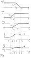
- the single figure shows, in diagram form, characteristic curves of various flaps of an air conditioning system of a motor vehicle and a characteristic curve of their total outflow cross section and the base load voltage of an intake blower, each as a function of the air outflow temperature.
- each air outflow channel can consist of several sub-channels, which lead to different areas of the vehicle interior and each contain its own flap.
- temperature control flap is understood below to mean the entirety of all actuators acting on the entire effective outflow cross section of the possibly multi-channel temperature control channel; the same applies analogously to the designations of defroster flap and footwell flap.
- characteristics of the flap angle ( ⁇ ) of the pivoting flaps are dependent on the temperature for the temperature flap, the defroster flap and the footwell flap the air flowing out of the air conditioning system and blown into the vehicle interior and serving as a temperature control fluid, as shown in the top three diagrams of the figure.
- the flap angle ( ⁇ T ) for the temperature flap decreases linearly as the air outflow temperature rises from a predetermined first temperature value (T 1 ) until it reaches zero at a second temperature value (T 2 ).
- the flap angle ( ⁇ E ) of the defroster flap increases linearly with increasing air outflow temperature (T L ) from a third temperature value (T 3 ) up to a maximum value of 44 °, which it achieves at a fourth temperature value (T 4 ) reached, which is smaller than the first temperature value (T 1 ).
- the flap angle ( ⁇ F ) of the footwell flap increases linearly from zero to a maximum value of 65 ° with increasing air outflow temperature (T L ) from a fifth temperature value (T 5 ) between the third (T 3 ) and the fourth (T 4 ) which is reached at a sixth temperature value (T 6 ) lying between the first (T 1 ) and the second (T 2 ).
- the control or regulating unit of the system now determines the resulting total outflow cross-section (A L ) of all air outflow channels of the system from the flap angle characteristic curves ( ⁇ T , ⁇ E , ⁇ F ) which are predetermined as a function of the air outflow temperature.
- the resulting characteristic of the total outflow cross section (A L ) as a function of the air outflow temperature (T L ) is shown in its qualitative course in the second bottom diagram of the figure.
- the total outflow cross section (A L ) with increasing air outflow temperature (T L ) from a value which is determined by the temperature control flap open at a low air outflow temperature, piece by piece from the third temperature value (T 3 ) to the sixth temperature value (T 6 ) increases linearly, namely between the fifth (T 5 ) and the fourth temperature value (T 4 ) with a greater gradient than between the third (T 3 ) and the fifth (T 5 ) or between the fourth (T 4 ) and the first temperature value (T 1 ).
- There is only a very slight increase between the first (T 1 ) and the sixth temperature value (T 6 ) since in this area the increasing opening of the footwell flap is almost compensated by the closing of the temperature flap. Since the temperature flap continues to close when the air outflow temperature (T L ) increases beyond the maximum opening angle through the footwell flap, the total outflow cross-section (A L ) drops again somewhat to the second temperature value (T 2 ).
- the base load voltage (U G ) of a delivery blower of the air conditioning system in the form of a suction blower is suitably regulated automatically in such a way that the air outflow speed is independent of the prevailing one Total outflow cross section (A L ) remains approximately constant.
- blower voltage characteristic curves for operating a heating and / or air conditioning system in accordance with the method can result, in each case To ensure that automatic changes in the effective outflow cross-section of the system, which result, for example, from flap adjustments, do not lead to a noticeably different air outflow speed at the respective outflow nozzles.
- the characteristic curve (U G ) used to adjust the base load delivery capacity of the blower as a function of the air outflow temperature (T L ) can alternatively be determined using the characteristic curve of the total outflow cross section (A L ) by means of a series of measurements, in which for a air flow temperature value or a respective total of set flap angles, the blower voltage is changed until a constant value for the air outflow speed is established.
- the method-based measure of keeping the air outflow speed constant can, if desired, also be restricted to a part of all air outflow ducts or flaps of the heating and / or air conditioning system, for example, when used in motor vehicles, to the outflow ducts which are particularly relevant for the passengers' sense of train, like the outflow channels assigned to the side ventilation nozzles.
Landscapes
- Engineering & Computer Science (AREA)
- Physics & Mathematics (AREA)
- Mechanical Engineering (AREA)
- Thermal Sciences (AREA)
- Chemical & Material Sciences (AREA)
- Combustion & Propulsion (AREA)
- General Engineering & Computer Science (AREA)
- General Physics & Mathematics (AREA)
- Automation & Control Theory (AREA)
- Air-Conditioning For Vehicles (AREA)
Abstract
Die Erfindung bezieht sich auf ein Verfahren zum Betrieb einer Heizungs- oder Klimaanlage, insbesondere für ein Kraftfahrzeug, bei dem ein Temperierfluid mittels eines in seiner Förderleistung regulierbaren Fördergebläses angesaugt und nach Temperierung über wenigstens einen Ausströmkanal ausgeblasen wird, dessen Ausströmquerschnitt mittels eines zugehörigen ansteuerbaren Stellglieds regulierbar ist. Erfindungsgemäß wird jedes Stellglied zur Ausströmquerschnittsregulierung selbsttätig in eine von der Ausströmtemperatur(TL) des Temperierfluids abhängige Stellung gesteuert, und die Fördergebläseleistung wird gemäß einer Kennlinie (UG) in Abhängigkeit von dieser Ausströmtemperatur eingestellt. Diese Kennlinie (UG) wird abhängig von den Stellungen der ausströmquerschnittsregulierenden Stellglieder und des dadurch bestimmten Gesamtausströmquerschnitts (AL) der Anlage derart ermittelt, daß sich unabhängig von der Ausströmtemperatur des Temperierfluids und damit unabhängig von den unterschiedlichen Stellungen der ausströmquerschnittsregulierenden Stellglieder eine im wesentlichen konstante Temperierfluid-Ausströmgeschwindigkeit ergibt. <IMAGE>The invention relates to a method for operating a heating or air conditioning system, in particular for a motor vehicle, in which a temperature control fluid is drawn in by means of a delivery blower that can be regulated in terms of its delivery rate, and is blown out after temperature control via at least one outflow channel, the outflow cross section of which can be regulated by means of an associated controllable actuator is. According to the invention, each actuator for regulating the outflow cross-section is automatically controlled into a position dependent on the outflow temperature (TL) of the temperature control fluid, and the delivery fan power is set according to a characteristic curve (UG) as a function of this outflow temperature. This characteristic curve (UG) is determined as a function of the positions of the control elements regulating the outlet cross-section and the overall outlet cross-section (AL) of the system determined in such a way that an essentially constant temperature-regulating fluid is determined independently of the outlet temperature of the temperature control fluid and thus independently of the different positions of the valve regulating the outlet cross-section. Outflow speed results. <IMAGE>
Description
Die Erfindung bezieht sich auf ein Verfahren zum Betrieb einer Heizungs- und/oder Klimaanlage nach dem Oberbegriff des Anspruchs 1. Derartige Verfahren werden beispielsweise zum Betrieb von in Kraftfahrzeugen eingebauten Heizungs- und/oder Klimaanlagen verwendet, wobei als Temperierfluid Luft und als Stellglieder zur Ausströmquerschnittsregulierung des oder der Luftausströmkanäle Klappen dienen, durch deren Verstellung der in den Fahrzeuginnenraum ausgeblasene Luftmassenstrom und damit die Heiz- bzw. Klimatisierungsleistung für den Fahrzeuginnenraum in gewünschter Weise eingestellt werden können.The invention relates to a method for operating a heating and / or air conditioning system according to the preamble of
Aus der Offenlegungsschrift DE 43 41 208 A1 ist ein Verfahren dieser Art zum Klimatisieren eines Fahrzeuginnenraumes bekannt, bei dem die zur Innenraumtemperaturregelung herangezogene Isttemperatur im Austrittsbereich des Luftstroms aus dem Fahrzeuginnenraum gemessen und zusätzlich die Eintrittstemperatur des Luftstroms in den Fahrzeuginnenraum erfaßt wird und der Luftmassenstrom dann, wenn die Innenraumtemperatur-Regeldifferenz einen vorgegebenen Wert überschreitet, derart eingeregelt wird, daß das mathematische Produkt aus einer Kennzahl für den Luftmassenstrom und dem Differenzbetrag von Eintrittstemperatur und Isttemperatur maximal wird.A method of this type for air conditioning a vehicle interior is known from the published patent application DE 43 41 208 A1, in which the actual temperature used for interior temperature control is measured in the outlet area of the air flow from the vehicle interior and the entry temperature of the air flow into the vehicle interior is also recorded and the air mass flow then, if the interior temperature control difference exceeds a predetermined value, it is adjusted so that the mathematical product of a key figure for the air mass flow and the difference between the inlet temperature and the actual temperature becomes maximum.
In der Offenlegungsschrift DE 41 13 374 A1 ist eine Regelungseinrichtung für eine Klimaanlage mit einem Lüfter zum Einblasen von Luft mit geregelter Temperatur in einen Raum sowie mit einer Fühlereinrichtung zum Messen der Hauttemperatur der in dem Raum befindlichen Personen beschrieben. Die Regelungseinrichtung ist mit Regelungsmitteln versehen, welche die Stärke des eingeblasenen Luftstroms in Abhängigkeit von der mittels der Fühlereinrichtung gemessenen Hauttemperatur sowie einer Soll-Hauttemperatur bestimmen, um eine optimale Soll-Temperaturempfindung für die Personen zu erreichen. Die elektronischen Regelungsmittel sind zum Aktivieren des Lüfters ausgebildet, der den Luftstrom mit der auf diese Weise ermittelten Stärke einbläst.The published patent application DE 41 13 374 A1 describes a control device for an air conditioning system with a fan for blowing air at a controlled temperature into a room and with a sensor device for measuring the skin temperature of the people in the room. The control device is provided with control means which determine the strength of the injected Determine the air flow as a function of the skin temperature measured by means of the sensor device and a target skin temperature in order to achieve an optimal target temperature sensation for the people. The electronic control means are designed to activate the fan, which blows in the air flow with the strength determined in this way.
Bei einer in der Offenlegungsschrift DE 41 00 817 A1 offenbarten Luftmengen-Regelanordnung für Kraftfahrzeuge kann die dem Fahrzeuginnenraum zuzuführende Luftmenge unter Berücksichtigung von Störeinflüssen, wie Fahrgeschwindigkeit, Fenster- und Schiebedachbetätigungen und dergleichen, in Abhängigkeit eines vorgegebenen Sollwertes reguliert werden. Dazu ist eine Vorrichtung zum Messen des Differenzdrucks zwischen dem in einem Luftführungskanal hinter einem Fördergebläse herrschenden Eingangsdruck und dem im Fahrzeuginnenraum herrschenden Druck vorgesehen, und die am Gebläsemotor angelegte Spannung ist vom in einer zugehörigen Regeleinheit durchgeführten Vergleich des gemessenen, ein Maß für die geförderte Luftmenge darstellenden Differenzdrucks mit einer einstellbar vorgegebenen Soll-Luftmenge abhängig. Es ist in dieser Veröffentlichung auch eine Regelanordnung erwähnt, bei der am Tachometer ein der Fahrgeschwindigkeit proportionales Signal abgegriffen wird, mit dem die Stellung einer Eingangsklappe im Luftführungskanal geregelt wird, um die dem Fahrzeuginnenraum zugeführte Luftmenge fahrgeschwindigkeitsabhängig einzustellen.In the case of an air quantity control arrangement for motor vehicles, which is disclosed in the published patent application DE 41 00 817 A1, the air quantity to be supplied to the vehicle interior can be regulated as a function of a predefined setpoint, taking into account interfering influences, such as driving speed, window and sunroof actuations and the like. For this purpose, a device is provided for measuring the differential pressure between the inlet pressure prevailing in an air duct behind a delivery blower and the pressure prevailing in the vehicle interior, and the voltage applied to the blower motor is based on a comparison of the measured value carried out in an associated control unit, which is a measure of the amount of air conveyed Differential pressure depending on an adjustable predetermined target air volume. A control arrangement is also mentioned in this publication, in which a signal proportional to the driving speed is tapped on the speedometer, with which the position of an input flap in the air duct is regulated in order to adjust the air quantity supplied to the vehicle interior as a function of the driving speed.
Allgemein läßt sich sagen, daß vollautomatische Klimaanlagen für Kraftfahrzeuge bekannt sind, bei denen die Gebläseleistung automatisch in Abhängigkeit von der Regelabweichung der Innenraumtemperatur, der Heizwasservorlauftemperatur oder Kühlwassertemperatur, dem Heizmodus oder Kühlmodus, dem Fahrgeschwindigkeitssignal, dem Filter- oder Umluftbetrieb, der Sonneneinstrahlung, einem fest programmierten Gebläsedrehzahl-Grundlastpegel und/oder von einzelnen Klappenstellungen eingeregelt wird, z.B. Anhebung der Gebläsedrehzahl um einen festen Wert bei Öffnen der Fußraumbelüftungsklappen, Absenkung der Drehzahl bei geöffneten Abschöpfklappen usw..In general, it can be said that fully automatic air conditioning systems for motor vehicles are known, in which the blower output is fixed depending on the control deviation of the interior temperature, the heating water supply temperature or cooling water temperature, the heating mode or cooling mode, the driving speed signal, the filter or recirculation mode, the sun exposure programmed fan speed base load level and / or from individual flap positions, eg increasing the fan speed by a fixed value when the footwell ventilation flaps are opened, reducing the speed when the skimmer flaps are open, etc.
Bekanntermaßen ist die Luftausblasgeschwindigkeit, mit der die Luft aus den entsprechenden Düsen einer Heizungs- und/oder Klimaanlage eines Kraftfahrzeuges in dessen Innenraum austritt, hauptsächlich abhängig von der Gebläsedrehzahl bzw. der Gebläseleistung, der konstant bleibenden Ansaugquerschnittfläche des Gebläsetraktes und vom sich verändernden Gesamtausströmquerschnitt der gesamten Heizungs- oder Klimaanlage. Wenn die Innenraumtemperatur den eingestellten Sollwert erreicht hat und alle anderen Parameter, die das Gebläse beeinflussen, annähernd konstant sind, läuft das Gebläse mit einer bestimmten Leistung auf einem Grundlastpegel. Durch die vollautomatische Anpassung der Klappenstellungen in Abhängigkeit von der Temperatur der ausgeblasenen Luft ändert sich in der Regel konstruktionsbedingt der Gesamtausströmquerschnitt der Heizungs- oder Klimaanlage und damit die Luftgeschwindigkeit an den Ausströmdüsen. Diese Änderung der Luftgeschwindigkeit wird vom Fahrgast als störend empfunden, da er vom Luftstrom meist direkt im Kopf-, Nacken- oder Brustbereich getroffen wird. Eine derartige Luftgeschwindigkeitsänderung aufgrund einer höher eingeregelten Belüftungstemperatur und damit einer Klappenstellungsänderung kann beispielsweise durch das Einfahren in einen Tunnel oder in ein Gewittergebiet verursacht sein. Wird die Gebläseleistung nicht an die Klappenstellungen angepaßt, so kann es zu Zugerscheinungen bei den Fahrzeuginsassen kommen.As is known, the air blow-out speed at which the air exits from the corresponding nozzles of a heating and / or air conditioning system of a motor vehicle into its interior mainly depends on the fan speed or the fan power, the constant intake cross-sectional area of the fan tract and the changing total discharge cross-section of the entire Heating or air conditioning. When the interior temperature has reached the setpoint and all other parameters influencing the fan are almost constant, the fan runs at a certain power at a base load level. Due to the fully automatic adjustment of the flap positions depending on the temperature of the blown air, the overall outflow cross-section of the heating or air conditioning system and thus the air speed at the outflow nozzles usually change due to the design. This change in air speed is perceived as a nuisance by the passenger, since the air flow usually hits him directly in the head, neck or chest area. Such an air speed change due to a higher regulated ventilation temperature and thus a flap position change can be caused, for example, by entering a tunnel or a thunderstorm area. If the blower output is not adapted to the flap positions, drafts can occur in the vehicle occupants.
Um dem abzuhelfen, wurde bereits eine Klimaanlage für Kraftfahrzeuge vorgeschlagen, bei der die Stellungen der vollautomatisch verstellbaren Klappen, wie Abschöpfklappen, Fußraumklappen, Entfrosterklappen und Temperierklappen, einzeln erfaßt werden und in einen Berechnungsalgorithmus für die Gebläsespannung eingehen. Die Anpassung dieser Vorgehensweise an die realen Fahrzeuggegebenheiten ist allerdings vergleichsweise aufwendig, da es schwierig ist, alle möglichen Bedingungen auszutesten, und eine Abhängigkeit von vielen weiteren Parametern gegeben ist. Außerdem wird ein relativ hoher Programmieraufwand benötigt.To remedy this, an air conditioning system for motor vehicles has already been proposed, in which the positions of the fully automatically adjustable flaps, such as skimmer flaps, footwell flaps, defroster flaps and temperature control flaps, are recorded individually and are incorporated into a calculation algorithm for the blower voltage. However, adapting this procedure to the real vehicle conditions is comparatively complex since it is difficult to test all possible conditions and there is a dependency on many other parameters. In addition, a relatively high programming effort is required.
Der Erfindung liegt als technisches Problem die Bereitstellung eines Verfahrens der eingangs genannten Art zugrunde, mit welchem auf vergleichsweise einfache Weise eine komfortable Temperierung gewährleistet wird, bei der Luftgeschwindigkeitsänderungen aufgrund automatischer Änderungen des effektiven Ausströmquerschnitts entgegengewirkt wird.The invention is based on the technical problem of providing a method of the type mentioned at the outset, with which a comfortable temperature control is ensured in a comparatively simple manner, in which changes in air speed due to automatic changes in the effective outflow cross section are counteracted.
Die Erfindung löst dieses Problem durch die Bereitstellung eines Verfahrens mit den Merkmalen des Anspruchs 1. Bei diesem Verfahren wird jedes zur Regulierung des Ausströmquerschnitts dienende Stellglied selbsttätig in eine Stellung gesteuert, die abhängig von der Temperatur des ausgeblasenen Temperierfluids gewählt ist, wozu zweckmäßigerweise eine entsprechende Kennlinie vorgegeben wird. Aus den Kennlinien der von der Temperierfluid-Ausblastemperatur abhängigen Stellungen der beteiligten Stellglieder und des sich daraus ergebenden Gesamtausströmquerschnitts wird in Abhängigkeit von der Temperatur des ausgeblasenen Temperierfluids eine Kennlinie ermittelt, gemäß welcher die Förderleistung des Fördergebläses reguliert wird. Dabei wird die Förderleistung so eingestellt, daß die Ausströmgeschwindigkeit des Temperierfluids unabhängig von der jeweiligen Ausströmtemperatur im wesentlichen konstant bleibt. Mit dieser Vorgehensweise wird mit relativ wenig Programmieraufwand und wenig Speicherbedarf in der Regelungselektronik sowie nur geringem Applikationsaufwand ein hoher Temperierkomfort beim Betrieb einer Heizungs- und/oder Klimaanlage, z.B. in einem Fahrzeug, erzielt. Die zur Änderung der Temperierleistung selbsttätig erfolgende Verstellung des Gesamtausströmquerschnitts wird von einer passenden Änderung der Förderleistung des Fördergebläses begleitet, die so gewählt ist, daß merkliche Schwankungen in der Temperierfluid-Ausströmgeschwindigkeit vermieden werden. Konstruktive Änderungen an der Anlage, z.B. an einem Ausströmkanal und/oder einem zugehörigen ausströmquerschnittsregulierenden Stellglied, können verhältnismäßig einfach und schnell durch geeignete Anpassung der Kennlinien berücksichtigt werden. Ebenso einfach ist die Anpassung des Anlagenbetriebs an eine Verschiebung einer Kennlinie für ein ausströmquerschnittsregulierendes Stellglied möglich, z.B. wenn bei Einsatz im Fahrzeug eine Fußraumklappe erst bei einer höheren Temperatur als bisher öffnen soll.The invention solves this problem by providing a method with the features of
Ein nach Anspruch 2 weitergebildetes Verfahren ist speziell auf die Gegebenheiten von Heizungs- und/oder Klimaanlagen angepaßt, die in Kraftfahrzeugen eingebaut sind und ein Ansauggebläse als Fördergebläse sowie diverse Klappen als ausströmquerschnittsregulierende Stellglieder beinhalten.A further developed method according to claim 2 is specially adapted to the conditions of heating and / or air conditioning systems which are installed in motor vehicles and contain an intake fan as a conveying fan and various flaps as regulating elements regulating the flow cross-section.
Eine bevorzugte Ausführungsform der Erfindung ist in der Zeichnung dargestellt und wird nachfolgend beschrieben.A preferred embodiment of the invention is shown in the drawing and is described below.
Die einzige Figur zeigt in Diagrammform Kennlinien verschiedener Klappen einer Klimaanlage eines Kraftfahrzeuges sowie eine Kennlinie von deren Gesamtausströmquerschnitt und der Grundlastspannung eines Ansauggebläses, jeweils in Abhängigkeit von der Luftausströmtemperatur.The single figure shows, in diagram form, characteristic curves of various flaps of an air conditioning system of a motor vehicle and a characteristic curve of their total outflow cross section and the base load voltage of an intake blower, each as a function of the air outflow temperature.
Das in Verbindung mit den in der Figur dargestellten Diagrammen nachfolgend beschriebene Verfahren dient zum Betrieb einer Klimaanlage eines Kraftfahrzeuges, die drei Luftausströmkanäle, und zwar einen Temperierkanal, einen Entfrosterkanal und einen Fußraumkanal, umfaßt, in denen jeweils eine schwenkbewegliche Klappe zur Regulierung des Ausströmquerschnitts angeordnet ist. Es versteht sich, daß je nach Systemauslegung jeder Luftausströmkanal mehrteilig aus mehreren Teilkanälen bestehen kann, die zu verschiedenen Bereichen des Fahrzeuginnenraums führen und jeweils eine eigene Klappe beinhalten. In diesem Sinne wird nachfolgend unter der Bezeichnung Temperierklappe die Gesamtheit aller auf den gesamten effektiven Ausströmquerschnitt des ggf. mehrkanaligen Temperierkanals einwirkenden Stellglieder verstanden, analoges gilt für die Bezeichnungen Entfrosterklappe und Fußraumklappe.The method described below in connection with the diagrams shown in the figure is used to operate an air conditioning system of a motor vehicle, which comprises three air outflow channels, namely a temperature control channel, a defroster channel and a footwell channel, in each of which a pivotable flap for regulating the outflow cross section is arranged . It goes without saying that, depending on the system design, each air outflow channel can consist of several sub-channels, which lead to different areas of the vehicle interior and each contain its own flap. In this sense, the term "temperature control flap" is understood below to mean the entirety of all actuators acting on the entire effective outflow cross section of the possibly multi-channel temperature control channel; the same applies analogously to the designations of defroster flap and footwell flap.
Verfahrensgemäß werden für die Temperierklappe, die Entfrosterklappe und die Fußraumklappe Kennlinien des Klappenwinkels (α) der schwenkbeweglichen Klappen in Abhängigkeit von der Temperatur der aus der Klimaanlage ausströmenden, in den Fahrzeuginnenraum eingeblasenen, als Temperierfluid dienenden Luft vorgegeben, wie sie in den obersten drei Diagrammen der Figur dargestellt sind. So nimmt der Klappenwinkel (αT) für die Temperierklappe, wie im obersten Diagramm gezeigt, bei höher werdender Luftausströmtemperatur ab einem vorgegebenen ersten Temperaturwert (T1) linear ab, bis er bei einem zweiten Temperaturwert (T2) den Wert null erreicht. Umgekehrt steigt der Klappenwinkel (αE) der Entfrosterklappe, wie im zweitobersten Diagramm gezeigt, mit steigender Luftausströmtemperatur (TL) ab einem dritten Temperaturwert (T3) linear bis auf einen Maximalwert von 44° an, den er bei einem vierten Temperaturwert (T4) erreicht, der kleiner als der erste Temperaturwert (T1) ist. Analog steigt der Klappenwinkel (αF) der Fußraumklappe bei zunehmender Luftausströmtemperatur (TL) ab einem zwischen dem dritten (T3) und dem vierten (T4) liegenden fünften Temperaturwert (T5) linear von null bis auf einen Maximalwert von 65° an, der bei einem zwischen dem ersten (T1) und dem zweiten (T2) liegenden sechsten Temperaturwert (T6) erreicht wird.According to the method, characteristics of the flap angle (α) of the pivoting flaps are dependent on the temperature for the temperature flap, the defroster flap and the footwell flap the air flowing out of the air conditioning system and blown into the vehicle interior and serving as a temperature control fluid, as shown in the top three diagrams of the figure. The flap angle (α T ) for the temperature flap, as shown in the top diagram, decreases linearly as the air outflow temperature rises from a predetermined first temperature value (T 1 ) until it reaches zero at a second temperature value (T 2 ). Conversely, as shown in the second diagram above, the flap angle (α E ) of the defroster flap increases linearly with increasing air outflow temperature (T L ) from a third temperature value (T 3 ) up to a maximum value of 44 °, which it achieves at a fourth temperature value (T 4 ) reached, which is smaller than the first temperature value (T 1 ). Similarly, the flap angle (α F ) of the footwell flap increases linearly from zero to a maximum value of 65 ° with increasing air outflow temperature (T L ) from a fifth temperature value (T 5 ) between the third (T 3 ) and the fourth (T 4 ) which is reached at a sixth temperature value (T 6 ) lying between the first (T 1 ) and the second (T 2 ).
Jedem Klappenwinkel (αT, αE, αF) und damit jeder Stellung der schwenkbeweglichen Klappen entspricht ein bestimmter effektiver Ausströmquerschnitt des zugehörigen Luftausströmkanals. Die Steuer- oder Regeleinheit der Anlage ermittelt nun aus den luftausströmtemperaturabhängig vorgegebenen Klappenwinkel-Kennlinien (αT, αE, αF) für jeden Luftausströmtemperaturwert den sich ergebenden gesamten Ausströmquerschnitt (AL) aller Luftausströmkanäle der Anlage. Die sich daraus ergebende Kennlinie des Gesamtausströmquerschnitts (AL) in Abhängigkeit von der Luftausströmtemperatur (TL) ist in ihrem qualitativen Verlauf im zweituntersten Diagramm der Figur wiedergegeben. Daraus ist erkennbar, daß der Gesamtausströmquerschnitt (AL) mit steigender Luftausströmtemperatur (TL) von einem Wert, der durch die bei kleiner Luftausströmtemperatur offene Temperierklappe bestimmt ist, ab dem dritten Temperaturwert (T3) bis zum sechsten Temperaturwert (T6) stückweise linear ansteigt, und zwar zwischen dem fünften (T5) und dem vierten Temperaturwert (T4) mit größerer Steigung als zwischen dem dritten (T3) und dem fünften (T5) bzw. zwischen dem vierten (T4) und dem ersten Temperaturwert (T1). Zwischen dem ersten (T1) und dem sechsten Temperaturwert (T6) ergibt sich nur noch ein sehr geringfügiger Anstieg, da in diesem Bereich das zunehmende Öffnen der Fußraumklappe vom einsetzenden Schließen der Temperierklappe annäherend kompensiert wird. Da sich bei weiter steigender Luftausströmtemperatur (TL) das Schließen der Temperierklappe über das Erreichen des maximalen Öffnungswinkels durch die Fußraumklappe hinaus fortsetzt, fällt der Gesamtausströmquerschnitt (AL) bis zum zweiten Temperaturwert (T2) wieder etwas ab.Every flap angle (α T , α E , α F ) and thus every position of the swiveling flaps corresponds to a certain effective outflow cross section of the associated air outflow channel. The control or regulating unit of the system now determines the resulting total outflow cross-section (A L ) of all air outflow channels of the system from the flap angle characteristic curves (α T , α E , α F ) which are predetermined as a function of the air outflow temperature. The resulting characteristic of the total outflow cross section (A L ) as a function of the air outflow temperature (T L ) is shown in its qualitative course in the second bottom diagram of the figure. From this it can be seen that the total outflow cross section (A L ) with increasing air outflow temperature (T L ) from a value which is determined by the temperature control flap open at a low air outflow temperature, piece by piece from the third temperature value (T 3 ) to the sixth temperature value (T 6 ) increases linearly, namely between the fifth (T 5 ) and the fourth temperature value (T 4 ) with a greater gradient than between the third (T 3 ) and the fifth (T 5 ) or between the fourth (T 4 ) and the first temperature value (T 1 ). There is only a very slight increase between the first (T 1 ) and the sixth temperature value (T 6 ), since in this area the increasing opening of the footwell flap is almost compensated by the closing of the temperature flap. Since the temperature flap continues to close when the air outflow temperature (T L ) increases beyond the maximum opening angle through the footwell flap, the total outflow cross-section (A L ) drops again somewhat to the second temperature value (T 2 ).
Unter Zugrundelegung der solchermaßen ermittelten Kennlinie für den Gesamtausströmquerschnitt (AL) in Abhängigkeit von der Luftausströmtemperatur (TL) wird verfahrensgemäß die Grundlastspannung (UG) eines Fördergebläses der Klimaanlage in Form eines Ansauggebläses geeignet selbsttätig so reguliert, daß die Luftausströmgeschwindigkeit unabhängig vom jeweils vorliegenden Gesamtausströmquerschnitt (AL) in etwa konstant bleibt. Zu diesem Zweck wird zur Einstellung dieser Gebläsespannung (UG) für den Grundlastbetrieb des Gebläses eine im untersten Diagramm der Figur gezeigte Kennlinie herangezogen, deren Verlauf proportional demjenigen der Gesamtausströmquerschnitt-Kennlinie (AL) folgt, wobei die Gebläsegrundlastspannung (UG) zwischen 1,2V und 1,6V variiert. Eine Änderung im Gesamtausströmquerschnitt (AL) aufgrund einer selbsttätigen Klappenverstellung hat somit eine proportionale Änderung der Grundlast-Förderleistung des Ansauggebläses derart zur Folge, daß die von der Klimaanlage temperierte und in den Fahrzeuginnenraum geleitete Luft im Grundlastbetrieb der Anlage, d.h. wenn keine sonstigen Gebläseleistungsänderungen infolge einer Innentemperatur-Regelabweichung oder dgl. vorliegen, mit im wesentlichen konstanter Geschwindigkeit aus den Luftausströmkanälen über zugehörige Düsen ausströmt.On the basis of the characteristic curve determined in this way for the total outflow cross section (A L ) as a function of the air outflow temperature (T L ), the base load voltage (U G ) of a delivery blower of the air conditioning system in the form of a suction blower is suitably regulated automatically in such a way that the air outflow speed is independent of the prevailing one Total outflow cross section (A L ) remains approximately constant. For this purpose, to adjust this blower voltage (U G ) for the base load operation of the blower, a characteristic curve shown in the bottom diagram of the figure is used, the course of which follows proportionally to that of the total outflow cross-section characteristic curve (A L ), the blower base load voltage (U G ) between 1 , 2V and 1.6V varies. A change in the total outflow cross section (A L ) due to an automatic flap adjustment therefore has a proportional change in the base load delivery capacity of the intake fan in such a way that the air tempered by the air conditioning system and directed into the vehicle interior during base load operation of the system, ie if no other fan power changes result an internal temperature control deviation or the like. Exits at a substantially constant speed from the air outflow channels via associated nozzles.
Es versteht sich, daß sich je nach Anlage unterschiedliche Gebläsespannungskennlinien zum verfahrensgemäßen Betrieb einer Heizungs- und/oder Klimaanlage ergeben können, um im jeweiligen Fall sicherzustellen, daß selbsttätige Änderungen im effektiven Ausströmquerschnitt der Anlage, die sich beispielsweise durch Klappenverstellungen ergeben, nicht zu einer merklich anderen Luftausströmgeschwindigkeit an den jeweiligen Ausströmdüsen führen. Die zur Einstellung der Grundlast-Förderleistung des Gebläses dienende Kennlinie (UG) in Abhängigkeit von der Luftausströmtemperatur (TL) kann alternativ zur oben beschriebenen Bestimmung über die Kennlinie des Gesamtausströmquerschnitts (AL) auch mittels einer Meßreihe ermittelt werden, bei welcher für einen jeweiligen Luftausströmtemperaturwert bzw. einer jeweiligen Gesamtheit von eingestellten Klappenwinkeln die Gebläsespannung so lange verändert wird, bis sich ein gleichbleibender Wert für die Luftausströmgeschwindigkeit einstellt. Es versteht sich, daß die verfahrensgemäße Maßnahme der Konstanthaltung der Luftausströmgeschwindigkeit auf Wunsch auch auf einen Teil aller Luftausströmkanäle bzw. Klappen der Heizungs- und/oder Klimaanlage beschränkt werden kann, beispielsweise bei Einsatz in Kraftfahrzeugen auf die für das Zugempfinden der Fahrzeuginsassen besonders relevanten Ausströmkanäle, wie die den seitlichen Belüftungsdüsen zugeordneten Ausströmkanäle.It goes without saying that, depending on the system, different blower voltage characteristic curves for operating a heating and / or air conditioning system in accordance with the method can result, in each case To ensure that automatic changes in the effective outflow cross-section of the system, which result, for example, from flap adjustments, do not lead to a noticeably different air outflow speed at the respective outflow nozzles. The characteristic curve (U G ) used to adjust the base load delivery capacity of the blower as a function of the air outflow temperature (T L ) can alternatively be determined using the characteristic curve of the total outflow cross section (A L ) by means of a series of measurements, in which for a air flow temperature value or a respective total of set flap angles, the blower voltage is changed until a constant value for the air outflow speed is established. It goes without saying that the method-based measure of keeping the air outflow speed constant can, if desired, also be restricted to a part of all air outflow ducts or flaps of the heating and / or air conditioning system, for example, when used in motor vehicles, to the outflow ducts which are particularly relevant for the passengers' sense of train, like the outflow channels assigned to the side ventilation nozzles.
Claims (2)
dadurch gekennzeichnet, daß
die ermittelte Förderleistungskennlinie (UG) für den Grundlastbetrieb des Fördergebläses herangezogen wird und die ausströmquerschnittsregulierenden Stellglieder wenigstens eine Temperierklappe, eine Entfrosterklappe und eine Fußraumklappe umfassen.The method of claim 1 for operating a heating and / or air conditioning system for a motor vehicle, further
characterized in that
the determined flow rate characteristic (U G ) is used for the base load operation of the delivery blower and the actuators regulating the outflow cross-section comprise at least one temperature control flap, a defroster flap and a footwell flap.
Applications Claiming Priority (2)
| Application Number | Priority Date | Filing Date | Title |
|---|---|---|---|
| DE19615239 | 1996-04-18 | ||
| DE19615239A DE19615239C1 (en) | 1996-04-18 | 1996-04-18 | Heating and/or air-conditioning system operating method for motor vehicle |
Publications (2)
| Publication Number | Publication Date |
|---|---|
| EP0802076A2 true EP0802076A2 (en) | 1997-10-22 |
| EP0802076A3 EP0802076A3 (en) | 1999-06-09 |
Family
ID=7791582
Family Applications (1)
| Application Number | Title | Priority Date | Filing Date |
|---|---|---|---|
| EP97102188A Withdrawn EP0802076A3 (en) | 1996-04-18 | 1997-02-12 | Method of operation of a heating and/or air conditioning device |
Country Status (3)
| Country | Link |
|---|---|
| US (1) | US5813600A (en) |
| EP (1) | EP0802076A3 (en) |
| DE (1) | DE19615239C1 (en) |
Cited By (2)
| Publication number | Priority date | Publication date | Assignee | Title |
|---|---|---|---|---|
| CN104764160A (en) * | 2015-03-30 | 2015-07-08 | 广东美的制冷设备有限公司 | Constant-air volume control method and device for indoor unit of air conditioner and indoor unit of air conditioner |
| US20240246391A1 (en) * | 2023-01-20 | 2024-07-25 | The Regents Of The University Of California | Method and system for adaptive cabin air quality control |
Families Citing this family (15)
| Publication number | Priority date | Publication date | Assignee | Title |
|---|---|---|---|---|
| DE19829567A1 (en) * | 1998-07-02 | 2000-01-05 | Mannesmann Vdo Ag | Air supply device and method for regulating the air supply in a vehicle |
| IT1310766B1 (en) * | 1999-12-03 | 2002-02-22 | Fiat Auto Spa | AIR SUPPLY GROUP FOR THE INTAKE OF AIR IN THE INTERIOR OF A VEHICLE. |
| FR2841501B1 (en) * | 2002-06-27 | 2005-11-18 | Renault Sa | METHOD AND DEVICE FOR CONTROLLING FLOW OF A VEHICLE AIR CONDITIONING APPARATUS |
| DE102004005678A1 (en) * | 2004-02-05 | 2005-09-01 | Bayerische Motoren Werke Ag | Ventilation, heating and / or air conditioning of a motor vehicle with an electronic control unit |
| US7681630B2 (en) * | 2004-12-07 | 2010-03-23 | Cnh America Llc | HVAC system for a work vehicle |
| US7415903B2 (en) * | 2006-12-22 | 2008-08-26 | Chrysler Llc | Method and system for an impact sled footwell intrusion test |
| US20080241606A1 (en) * | 2007-03-30 | 2008-10-02 | Gallagher Emerson R | Method and apparatus for humidifying a gas in fuel cell systems |
| JP2009001140A (en) * | 2007-06-21 | 2009-01-08 | Komatsu Ltd | Air conditioner |
| DE102008031712A1 (en) * | 2008-07-04 | 2010-01-07 | Bayerische Motoren Werke Aktiengesellschaft | Vehicle heating and / or air conditioning with automatic heating and air conditioning |
| DE102010041440A1 (en) * | 2010-09-27 | 2012-03-29 | Siemens Aktiengesellschaft | Vehicle with a cooled by means of a cooling air mass flow component |
| JP5980637B2 (en) * | 2012-09-26 | 2016-08-31 | シャープ株式会社 | Air conditioner |
| US10060642B2 (en) | 2014-10-22 | 2018-08-28 | Honeywell International Inc. | Damper fault detection |
| KR101673762B1 (en) * | 2015-04-28 | 2016-11-07 | 현대자동차주식회사 | System and method for controlling air conditioner for vehicle |
| US11029057B2 (en) * | 2016-05-31 | 2021-06-08 | Robert J. Mowris | Economizer controller calibration |
| CN117366784B (en) * | 2023-12-07 | 2024-03-15 | 珠海格力电器股份有限公司 | Abnormality detection method and device for air inlet baffle device, storage medium and air conditioner |
Citations (3)
| Publication number | Priority date | Publication date | Assignee | Title |
|---|---|---|---|---|
| DE4113374A1 (en) | 1990-04-24 | 1991-10-31 | Toyoda Chuo Kenkyusho Kk | CONTROL UNIT FOR AN AIR CONDITIONING |
| DE4100817A1 (en) | 1991-01-14 | 1992-07-16 | Behr Gmbh & Co | AIR QUANTITY CONTROL ARRANGEMENT FOR MOTOR VEHICLES |
| DE4341208A1 (en) | 1993-12-03 | 1995-06-08 | Bayerische Motoren Werke Ag | Air-conditioning system for road vehicles |
Family Cites Families (8)
| Publication number | Priority date | Publication date | Assignee | Title |
|---|---|---|---|---|
| JPS6061322A (en) * | 1983-09-14 | 1985-04-09 | Nissan Shatai Co Ltd | Automatic air conditioner for vehicle |
| US4748822A (en) * | 1986-12-04 | 1988-06-07 | Carrier Corporation | Speed control of a variable speed air conditioning system |
| JPH01208216A (en) * | 1986-12-19 | 1989-08-22 | Asmo Co Ltd | Air-conditioner for vehicle |
| JPH0224214A (en) * | 1988-07-13 | 1990-01-26 | Hitachi Ltd | Control device for air conditioner in automobile |
| JP2680391B2 (en) * | 1988-12-28 | 1997-11-19 | 日産自動車株式会社 | Heater unit for automotive air conditioner |
| US5400963A (en) * | 1991-07-10 | 1995-03-28 | Naldec Corporation | Method and apparatus for controlling vehicle air conditioner |
| JP3161055B2 (en) * | 1992-07-15 | 2001-04-25 | 株式会社デンソー | Vehicle air conditioner |
| JP3533716B2 (en) * | 1994-09-09 | 2004-05-31 | 株式会社デンソー | Vehicle air conditioner |
-
1996
- 1996-04-18 DE DE19615239A patent/DE19615239C1/en not_active Expired - Fee Related
-
1997
- 1997-02-12 EP EP97102188A patent/EP0802076A3/en not_active Withdrawn
- 1997-04-18 US US08/840,916 patent/US5813600A/en not_active Expired - Fee Related
Patent Citations (3)
| Publication number | Priority date | Publication date | Assignee | Title |
|---|---|---|---|---|
| DE4113374A1 (en) | 1990-04-24 | 1991-10-31 | Toyoda Chuo Kenkyusho Kk | CONTROL UNIT FOR AN AIR CONDITIONING |
| DE4100817A1 (en) | 1991-01-14 | 1992-07-16 | Behr Gmbh & Co | AIR QUANTITY CONTROL ARRANGEMENT FOR MOTOR VEHICLES |
| DE4341208A1 (en) | 1993-12-03 | 1995-06-08 | Bayerische Motoren Werke Ag | Air-conditioning system for road vehicles |
Cited By (3)
| Publication number | Priority date | Publication date | Assignee | Title |
|---|---|---|---|---|
| CN104764160A (en) * | 2015-03-30 | 2015-07-08 | 广东美的制冷设备有限公司 | Constant-air volume control method and device for indoor unit of air conditioner and indoor unit of air conditioner |
| CN104764160B (en) * | 2015-03-30 | 2017-06-16 | 广东美的制冷设备有限公司 | The constant air capacity control of air conditioner room unit, device and air conditioner room unit |
| US20240246391A1 (en) * | 2023-01-20 | 2024-07-25 | The Regents Of The University Of California | Method and system for adaptive cabin air quality control |
Also Published As
| Publication number | Publication date |
|---|---|
| EP0802076A3 (en) | 1999-06-09 |
| DE19615239C1 (en) | 1997-03-20 |
| US5813600A (en) | 1998-09-29 |
Similar Documents
| Publication | Publication Date | Title |
|---|---|---|
| EP0316545B1 (en) | Air-conditioning system | |
| DE19615239C1 (en) | Heating and/or air-conditioning system operating method for motor vehicle | |
| DE4119042C2 (en) | Control device for an air conditioning system for vehicles | |
| EP1708901A1 (en) | Heating, ventilating or air-conditioning system | |
| EP0805056A2 (en) | Vehicle air-conditioning with air directing means regulated by solar radiation | |
| DE3016679A1 (en) | VENTILATION, HEATING AND / OR AIR CONDITIONING FOR MOTOR VEHICLES | |
| DE4425697C2 (en) | air conditioning | |
| EP0495201B1 (en) | Device for controlling the air flow in motor vehicles | |
| DE3928944C3 (en) | Air conditioning for vehicles | |
| DE3343487C2 (en) | ||
| DE19829567A1 (en) | Air supply device and method for regulating the air supply in a vehicle | |
| DE102014109925A1 (en) | Multi-zone air-conditioning system | |
| DE10036502C1 (en) | Air conditioning system for vehicle compares sensor signal with reference signal for reference operating state to determine whether degree of filter fouling exceeds defined value | |
| DE19629280B4 (en) | heater | |
| DE10235526A1 (en) | Controlling/regulating heating/air conditioning system ventilation device for vehicle interior, involves controlling air flow path blocking device so air quantity flowing out of air outlet varies dynamically or cyclically | |
| DE4013043A1 (en) | Multiple outlet current-generating method - involves mixing part of single inlet current with outlet one and varies flow | |
| EP0876930B1 (en) | Air conditioning device for the interior of a vehicle | |
| EP0847887B1 (en) | Multi-channel heating or air conditioning unit | |
| DE2634713A1 (en) | Bus interior heating and ventilating system - has manually controlled air supply to drivers cab separate from that to passengers compartment which is controlled by thermostatic valve | |
| EP1187733B1 (en) | Device for controlling the interior temperature of a motor vehicle | |
| DE19742106A1 (en) | Arrangement for delivering air to the interior of a motor vehicle | |
| DE3217825A1 (en) | Air-conditioning unit for an air-cooled motor vehicle | |
| DE102024106861B3 (en) | AIR DIFFUSER SYSTEM FOR A VEHICLE | |
| DE10036509C1 (en) | Air outlet for air flowing into vehicle interior has sensors for measuring speed of sub-flows of air near outlet opening mounted in channel interior behind deflection elements near outlet | |
| EP0771276B1 (en) | Air-conditioning device intended in particular for use in a motor vehicle, with atmosphere-side outlet temperature regulation |
Legal Events
| Date | Code | Title | Description |
|---|---|---|---|
| PUAI | Public reference made under article 153(3) epc to a published international application that has entered the european phase |
Free format text: ORIGINAL CODE: 0009012 |
|
| AK | Designated contracting states |
Kind code of ref document: A2 Designated state(s): ES FR GB IT SE |
|
| RAP1 | Party data changed (applicant data changed or rights of an application transferred) |
Owner name: DAIMLERCHRYSLER AG |
|
| PUAL | Search report despatched |
Free format text: ORIGINAL CODE: 0009013 |
|
| AK | Designated contracting states |
Kind code of ref document: A3 Designated state(s): ES FR GB IT SE |
|
| 17P | Request for examination filed |
Effective date: 19990514 |
|
| GRAG | Despatch of communication of intention to grant |
Free format text: ORIGINAL CODE: EPIDOS AGRA |
|
| 17Q | First examination report despatched |
Effective date: 20010418 |
|
| GRAG | Despatch of communication of intention to grant |
Free format text: ORIGINAL CODE: EPIDOS AGRA |
|
| GRAH | Despatch of communication of intention to grant a patent |
Free format text: ORIGINAL CODE: EPIDOS IGRA |
|
| STAA | Information on the status of an ep patent application or granted ep patent |
Free format text: STATUS: THE APPLICATION IS DEEMED TO BE WITHDRAWN |
|
| 18D | Application deemed to be withdrawn |
Effective date: 20010901 |