EP0799685A2 - Pince de serrage avec rouleaux de guidage - Google Patents
Pince de serrage avec rouleaux de guidage Download PDFInfo
- Publication number
- EP0799685A2 EP0799685A2 EP97105090A EP97105090A EP0799685A2 EP 0799685 A2 EP0799685 A2 EP 0799685A2 EP 97105090 A EP97105090 A EP 97105090A EP 97105090 A EP97105090 A EP 97105090A EP 0799685 A2 EP0799685 A2 EP 0799685A2
- Authority
- EP
- European Patent Office
- Prior art keywords
- rollers
- protective hood
- roller
- clamping body
- horizontal
- Prior art date
- Legal status (The legal status is an assumption and is not a legal conclusion. Google has not performed a legal analysis and makes no representation as to the accuracy of the status listed.)
- Granted
Links
Images

Classifications
-
- B—PERFORMING OPERATIONS; TRANSPORTING
- B29—WORKING OF PLASTICS; WORKING OF SUBSTANCES IN A PLASTIC STATE IN GENERAL
- B29C—SHAPING OR JOINING OF PLASTICS; SHAPING OF MATERIAL IN A PLASTIC STATE, NOT OTHERWISE PROVIDED FOR; AFTER-TREATMENT OF THE SHAPED PRODUCTS, e.g. REPAIRING
- B29C55/00—Shaping by stretching, e.g. drawing through a die; Apparatus therefor
- B29C55/02—Shaping by stretching, e.g. drawing through a die; Apparatus therefor of plates or sheets
- B29C55/20—Edge clamps
-
- B—PERFORMING OPERATIONS; TRANSPORTING
- B65—CONVEYING; PACKING; STORING; HANDLING THIN OR FILAMENTARY MATERIAL
- B65H—HANDLING THIN OR FILAMENTARY MATERIAL, e.g. SHEETS, WEBS, CABLES
- B65H23/00—Registering, tensioning, smoothing or guiding webs
- B65H23/02—Registering, tensioning, smoothing or guiding webs transversely
- B65H23/022—Registering, tensioning, smoothing or guiding webs transversely by tentering devices
- B65H23/028—Registering, tensioning, smoothing or guiding webs transversely by tentering devices by clips
Definitions
- the invention relates to a tensioning block with roller bearings, fastened in a web support of a film stretching machine, with a flexible, vertically clamped guide belt, against which horizontal rollers roll from both sides, and with a vertical roller over which a clip chain is guided.
- transverse stretching frame For orientation in the transverse direction, films that are to be stretched biaxially are passed through a so-called transverse stretching frame.
- This transverse stretching frame has a double-T beam, through which a clip chain runs.
- Tension clips are attached to the clip chain, which grip the film web in the edge area as gripper elements.
- bearing rollers over which the clip chain runs, these bearing rollers generally consisting of deep groove ball bearings which are provided with a long-acting lubricant during manufacture.
- a clip chain of tension clips with roller bearings in the tenter frame of a film stretching machine which has a flexible, seamless and vertically clamped guide rail, against which the horizontal tensioning forces absorbing from both sides are applied, whereby the weight of the chain is carried by vertical rollers.
- the clamping of the guide rail is such that running surfaces for the horizontal rollers of the clamping clips are formed essentially symmetrically to the plane of the material to be treated both above and below the clamping point.
- the guide rail is clamped on a web or pin which is arranged on the rear wall of a housing enclosing the dome chain track. The housing completely encloses the tension clip and therefore takes up a lot of space and increases the weight of the tension clip considerably, so that the clip chain is very heavy has, which makes the construction of the tenter of the film stretching machine correspondingly heavy and structurally complex.
- DE-C - 29 49 858 describes a chain chain conveyor in a tenter for longitudinal and transverse stretching of material webs with a chain conveyor carrier consisting of articulated sections.
- Seamless and endless, round-profiled running and support rails are integrated in the chain track carrier, with helical spring-like bridging elements arranged in the kinks between the sections and connecting the ends of the running and carrying rails.
- the running and support rails are mounted one above the other in a vertical plane holding bearings, the ends of the running and support rails are connected to one another in the kink points of the sections of the chain track carrier by a composite spring assembly.
- the spring assembly consists of spring leaves that are arranged on both sides of a flexible square rod and are supported on the inner surface of the bridging element. The flexible square rod is passed through the bridging link.
- oil stains By increasing the production speed, so-called “oil stains” appear on the films when the films are stretched. These stain-like impurities
- the freshly greased bearing rollers tend to release part of their bearing grease as a grease mist. Due to the turbulent flow conditions in the vicinity of the clip chain, these grease mists also spread in the direction of the film and are deposited in the edge area of the film. The resulting grease stains are particularly noticeable after the metallization of electrical foils.
- the object of the invention is therefore to improve tension clips of the type described in the introduction in such a way that precipitation of lubricants from the bearing rollers of the tension clips onto the film is avoided without wider seam strips of the film occurring and without the external dimensions of the tension clips resulting from appropriate shields must be enlarged.
- the clamping clip consists of a clamping body and a roller part
- the clamping body contains horizontal and vertical rollers and is covered by a protective cover, the shape of which is adapted to the geometry of the rollers, so that lubricant mist from the Casters are reflected on the inside of the protective hood.
- the protective hood has two holes on the top, which are aligned with corresponding threaded holes in the clamping body, and the protective hood is fastened to the clamping body by means of screws which are passed through the holes and screwed into the threaded holes.
- a direct cover as dust protection for the individual bearing rollers is generally not sufficient to prevent lubricant mist from escaping from the bearing rollers to the desired extent, since the cover often leaks during operation at higher production speeds.
- the protective hood according to the invention brings considerable cost advantages, since sealed bearing rollers are twice as expensive as non-sealed bearing rollers. Given the large number of bearing rollers in a chain, this leads to an unacceptable increase in the price of the chain.
- the tension clip 1 shows a side view of a tension clip 1, which is arranged in a web carrier 18, which has a double-T cross-section, of a film stretching machine.
- the tension clip 1 is part of a clip chain 30 (see FIG. 2), which is movable along a closed guideway.
- the clamping clip 1 consists of a clamping body 2 and a rolling part 3, between which a film is clamped in a film clamping plane 19 during the width stretching.
- In the clamping body 2 there are three horizontal rollers 4, 5, 7, which form a triangular arrangement, and a vertical roller 6.
- Two horizontal rollers 8 and 9 are arranged in the roller part 3 of the tension clamp 1.
- the tenter chain 30 is guided over the vertical roller 6.
- a protective hood 17, the outlines of which are drawn in the view according to FIG. 1, has a shape which is adapted to the geometry of the rollers 4, 5, 6, which ensures that lubricant mist which emerges from the rollers is on the inside of the Protective hood 17.
- the clamping clip 1 contains two flaps 10, 11 which are rotatably mounted about a bolt 34 which is fastened to the clamping body 2.
- the arms of the flaps 10, 11 pointing downward from the bolt 34 clamp in the film clamping plane 19 an edge strip of the film between an underside 35 of the flaps and a contact surface 36 of the clamping body 2.
- Folding springs 12 and 13 for example leaf springs, are preloaded at one end in the clamping body 2, while their other end is connected to the lower arm of the flaps 10 and 11, somewhat below the bolt 34.
- the flap springs 12 and 13 are convexly curved upwards and exert a torque in a clockwise direction on the flaps 10 and 11 so that they hold the flaps in their closed position.
- a flexible, vertically clamped guide band 16 which is fastened in the center to the web carrier 18 in a manner not shown.
- the following explanations refer to a 6-roller dome. They also apply analogously to tension clamps with a different number of rolls, e.g. 7 or 9 rolls.
- the three horizontal rollers 4, 5 and 7 in the clamping body 2, as well as the two horizontal rollers 8 and 9 in the roller part 3, lie from both sides on the guide belt, which consists, for example, of laminated cores and forms corresponding running surfaces for the adjacent rollers.
- the rollers 4, 5, 6 and 7 in the clamping body 2, as well as the rollers 8 and 9 in the roller part 3, are equipped with covers 33, which serve as dust protection for the bearing rollers.
- the protective hood 17 has two holes 22, 23 on the upper side, which are aligned with corresponding threaded holes 20, 21 in the clamping body 2. After the protective hood 17 is slid onto the clamping body 2, it is screwed through the holes 22 and 23 and into the threaded holes 20, 21st are screwed, attached to the clamp body 2. It can be seen from FIG. 2 that the two horizontal rollers 8, 9 in the roller part 3 of the tensioning block 1 are aligned at right angles to the first and second horizontal rollers 4 and 5 in the clamping body 2. In Figure 2, two tension clips are shown side by side, which are arranged for example at the narrowest point of the deflection of the clip chain 30.
- connection of the two tension clamps 1, 1 takes place by means of chain links, not shown, which are rotatable about chain pins 14 and 15, as indicated in FIG. 1.
- chain links not shown
- These link plates can be connected to the chain bolts via sleeves and bushings, not shown.
- These link plates are pushed into each other in the area of the link pins, ie one link plate has a thickness that is slightly smaller than the inner distance between the two links of the other link plate.
- the teeth of a gear wheel, not shown, which drives the clip chain 30 engage in the link plates.
- the three horizontal rollers 4, 5 and 7 of the clamping body 2 are arranged triangularly in one plane, as can be seen from Figure 2.
- the film clamping plane 19 runs in the center in the longitudinal direction to the horizontal rollers.
- the vertical roller 6 in FIG. 1 is aligned with the guide belt 16 and is located with its lower edge at the level of the three horizontal rollers 4, 5 and 7.
- a first embodiment of the protective hood 17 encloses the first and second horizontal rollers 4, 5 and the vertical roller 6.
- the third horizontal roller 7 is not enclosed by this protective hood 17 and is located in the clamping body 2 between an oblique lower edge 31 of the protective hood 17 and the Top of the roller part 3.
- This first embodiment of the protective hood does not cover the third horizontal roller 7 on the side, but at the top, so that the lubricant mist rising from the bearing can be deposited on the inside of the protective hood 17.
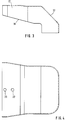
- the top view of the protective hood 17 in FIG. 4 shows the holes 22, 23 and the rounded transition from the side surfaces to the front surface.
- the side surfaces run obliquely outwards in the direction of the rear surface of the protective hood 17.
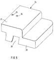
- FIG. 5 shows a second embodiment of a protective hood 24, which consists of a base part 28 and an upper part 27 set back with respect to the front edge of the base part 28.
- the protective hood 24 completely covers the three horizontal rollers 4, 5 and 7 and the vertical roller 6 of the clamping body 2.
- the base part 28 has an incision 29 in each side surface. Similar to the protective hood 17, there are two holes 25 and 26 in the upper part 27 for fastening the protective hood 24 to the clamping body 2 by means of two screws on the upper side of the protective hood 24.
- the protective hoods 17 and 24 are either made of compression-molded material, such as sheet metal, or of deep-drawn or injection-molded plastic.
- the roller part 3 can also be covered by a protective hood, the geometry of which is adapted to the shape of the rollers 8, 9 in the roller part.
- the roller part can also contain more than two rollers.
Landscapes
- Engineering & Computer Science (AREA)
- Mechanical Engineering (AREA)
- Shaping By String And By Release Of Stress In Plastics And The Like (AREA)
- Advancing Webs (AREA)
Applications Claiming Priority (2)
| Application Number | Priority Date | Filing Date | Title |
|---|---|---|---|
| DE19613562 | 1996-04-04 | ||
| DE19613562A DE19613562A1 (de) | 1996-04-04 | 1996-04-04 | Spannkluppe mit Rollenlagerung |
Publications (3)
| Publication Number | Publication Date |
|---|---|
| EP0799685A2 true EP0799685A2 (fr) | 1997-10-08 |
| EP0799685A3 EP0799685A3 (fr) | 1997-11-05 |
| EP0799685B1 EP0799685B1 (fr) | 1999-11-17 |
Family
ID=7790512
Family Applications (1)
| Application Number | Title | Priority Date | Filing Date |
|---|---|---|---|
| EP97105090A Expired - Lifetime EP0799685B1 (fr) | 1996-04-04 | 1997-03-26 | Pince de serrage avec rouleaux de guidage |
Country Status (4)
| Country | Link |
|---|---|
| US (1) | US5768755A (fr) |
| EP (1) | EP0799685B1 (fr) |
| JP (1) | JPH1045293A (fr) |
| DE (2) | DE19613562A1 (fr) |
Cited By (2)
| Publication number | Priority date | Publication date | Assignee | Title |
|---|---|---|---|---|
| EP1147876A1 (fr) * | 2000-04-12 | 2001-10-24 | Flexafilms S.p.A. | Dispositif et procédé pour étirer dans le sens transversal une bande de film en matériau plastique |
| CN111170054A (zh) * | 2018-11-12 | 2020-05-19 | 平野技研工业株式会社 | 拉幅机装置以及使用了该拉幅机装置的热处理装置 |
Families Citing this family (12)
| Publication number | Priority date | Publication date | Assignee | Title |
|---|---|---|---|---|
| DE19515036A1 (de) * | 1995-04-24 | 1996-10-31 | Brueckner Maschbau | Transportvorrichtung sowie zugehörige Führungsschiene |
| DE19708620C1 (de) * | 1997-03-03 | 1998-08-27 | Dornier Gmbh Lindauer | Führungsschiene für Spannkluppen in Spannmaschinen, insbesondere Folienreckmaschinen |
| US5896631A (en) * | 1997-04-21 | 1999-04-27 | Lindauer Dornier Gesellschaft Mbh | Spring steel tape tentering clamp guide rail with such tape |
| JP4598240B2 (ja) | 1999-06-24 | 2010-12-15 | アスリートFa株式会社 | ボール搭載装置及びボール搭載方法 |
| JP4310286B2 (ja) * | 2004-03-31 | 2009-08-05 | 三菱重工業株式会社 | 潤滑油組成物 |
| KR100596133B1 (ko) | 2004-07-27 | 2006-07-03 | 이화기계공업(주) | 텐터기의 다단 슬라이딩식 폭출 샤프트 커버 |
| JP5371523B2 (ja) * | 2009-04-14 | 2013-12-18 | 東芝機械株式会社 | フィルム延伸装置およびフィルムの延伸方法 |
| CN106513332B (zh) * | 2017-01-06 | 2023-11-24 | 浙江爱易特智能技术有限公司 | 一种推力球轴承座下料总装 |
| CN107521084B (zh) * | 2017-08-24 | 2023-12-26 | 李勇 | 一种双拉铗子 |
| CN112275651A (zh) * | 2020-08-28 | 2021-01-29 | 南京雷石电子科技有限公司 | 一种电路板检测装置用夹持滑轨和使用方法 |
| JP7576522B2 (ja) * | 2021-07-16 | 2024-10-31 | 株式会社日本製鋼所 | リンク装置および延伸機 |
| CN117644644B (zh) * | 2024-01-30 | 2024-04-05 | 合肥东昇智能装备股份有限公司 | 一种双拉链夹 |
Family Cites Families (22)
| Publication number | Priority date | Publication date | Assignee | Title |
|---|---|---|---|---|
| GB1136709A (en) * | 1964-11-28 | 1968-12-18 | Dornier Gmbh Lindauer | Improvements in or relating to tenter frames |
| US3457608A (en) * | 1965-09-15 | 1969-07-29 | Dornier Gmbh Lindauer | Chain track assembly for tenter clips |
| US3500515A (en) * | 1968-03-27 | 1970-03-17 | Proctor & Schwartz Inc | Tentering machine |
| DE6801212U (de) * | 1968-10-08 | 1969-06-26 | Brueckner Maschb Gernot Brueck | Spannkluppenkette |
| US3748704A (en) * | 1972-01-04 | 1973-07-31 | Kampf Maschf Erwin | Clamp for biaxial stretching machines |
| DE2749119A1 (de) * | 1977-11-03 | 1979-05-10 | Dornier Gmbh Lindauer | Fuehrungseinrichtung fuer zu einer endlosen kette zusammengefasste gleitend gefuehrte spannkluppen in spannrahmen |
| US4134189A (en) * | 1977-12-16 | 1979-01-16 | Richter Hans H | Tentering clip chain |
| DE2844432C2 (de) * | 1978-10-12 | 1985-06-27 | Lindauer Dornier Gmbh, 8990 Lindau | Kluppenkettenbahn |
| DE2949858C2 (de) * | 1979-12-12 | 1982-04-01 | Lindauer Dornier Gmbh, 8990 Lindau | Kluppenkettenbahn |
| GB8425045D0 (en) * | 1984-10-04 | 1984-11-07 | Procter & Schwartz Ltd | Stenter frame chain assembly |
| JPS61124462A (ja) * | 1984-11-22 | 1986-06-12 | Mitsubishi Heavy Ind Ltd | テンタクリツプ |
| JP2510990B2 (ja) * | 1986-05-08 | 1996-06-26 | 三菱重工業株式会社 | 延伸機 |
| EP0206317A3 (fr) * | 1985-06-25 | 1988-10-05 | Mitsubishi Jukogyo Kabushiki Kaisha | Machine d'étirage |
| DE3928454A1 (de) * | 1989-08-29 | 1991-03-07 | Kampf Gmbh & Co Maschf | Kluppe und transportvorrichtung |
| DE3939086C2 (de) * | 1989-11-25 | 1995-10-05 | Dornier Gmbh Lindauer | Spannkluppe mit Rollenlagerung |
| US5287958A (en) * | 1990-03-01 | 1994-02-22 | Bruckner Maschinenbau Gernot Bruckner Gmbh & Co. Kg | Device for stretching and fixing sheet |
| DE4006440A1 (de) * | 1990-03-01 | 1991-09-05 | Brueckner Maschbau | Vorrichtung zum breitstrecken sowie fixieren von folienbahnen |
| DE4014227A1 (de) * | 1990-05-03 | 1991-11-07 | Brueckner Maschbau | Kluppe |
| US5159733A (en) * | 1991-10-02 | 1992-11-03 | E. I. Du Pont De Nemours And Company | Tenter-type stretcher having means for detecting clip obstructions |
| FR2686041B1 (fr) * | 1992-01-13 | 1996-07-19 | Darlet Marchante Tech Sa | Dispositif d'etirage transversal pour la fabrication de films biorientes. |
| DE4316383A1 (de) * | 1993-05-17 | 1994-11-24 | Hoechst Ag | Verfahren und Vorrichtung zur Vergleichmäßigung der Wickelhärten eines Rollenprofils eines Folienwickels |
| US5613284A (en) * | 1996-04-30 | 1997-03-25 | Marshall & Williams Company | Tenter assembly and method |
-
1996
- 1996-04-04 DE DE19613562A patent/DE19613562A1/de not_active Withdrawn
-
1997
- 1997-03-26 EP EP97105090A patent/EP0799685B1/fr not_active Expired - Lifetime
- 1997-03-26 DE DE59700712T patent/DE59700712D1/de not_active Expired - Fee Related
- 1997-03-31 US US08/831,006 patent/US5768755A/en not_active Expired - Fee Related
- 1997-04-03 JP JP9085174A patent/JPH1045293A/ja not_active Withdrawn
Cited By (2)
| Publication number | Priority date | Publication date | Assignee | Title |
|---|---|---|---|---|
| EP1147876A1 (fr) * | 2000-04-12 | 2001-10-24 | Flexafilms S.p.A. | Dispositif et procédé pour étirer dans le sens transversal une bande de film en matériau plastique |
| CN111170054A (zh) * | 2018-11-12 | 2020-05-19 | 平野技研工业株式会社 | 拉幅机装置以及使用了该拉幅机装置的热处理装置 |
Also Published As
| Publication number | Publication date |
|---|---|
| EP0799685A3 (fr) | 1997-11-05 |
| DE59700712D1 (de) | 1999-12-23 |
| DE19613562A1 (de) | 1997-10-09 |
| JPH1045293A (ja) | 1998-02-17 |
| US5768755A (en) | 1998-06-23 |
| EP0799685B1 (fr) | 1999-11-17 |
Similar Documents
| Publication | Publication Date | Title |
|---|---|---|
| EP0291775B1 (fr) | Appareil pour le traitement biaxial simultané de films | |
| EP0799685B1 (fr) | Pince de serrage avec rouleaux de guidage | |
| DE3419878C1 (de) | Tragplatte insbesondere Transportwagen- od. Palettentragplatte mit Spannvorrichtung | |
| DE1102381B (de) | Vorrichtung zum laufenden, geregelten kontinuierlichen Strecken und Schrumpfen von bahnenfoermigem Material, insbesondere thermoplastischen Kunststoffilmen | |
| DE2006428B2 (de) | Halterahmen für eine aus thermoplastischem Material bestehende Tafel zum Thermoverformen | |
| EP0785858B1 (fr) | Dispositif de fabrication de bandes de feuilles etirees en longueur et/ou en largeur, notamment etirees en meme temps le long de deux axes | |
| DE60003303T2 (de) | Vorrichtung zum laden von folien in einer maschine zum einwickeln von produkten | |
| DE4241213C2 (de) | Vorrichtung zur simultanen, biaxialen Behandlung von Folienbahnen | |
| DE3928454A1 (de) | Kluppe und transportvorrichtung | |
| DE4339092C2 (de) | Transportvorrichtung für Flachmaterial | |
| DE2840763A1 (de) | Spannklemmenkette | |
| DE2145447A1 (de) | Vorrichtung zum Anbringen eines rückseitigen Teiles mit einem schmelzbaren thermoplastischen Material auf mindestens einer seiner beiden Seiten an einem Teil aus Textilmaterial | |
| EP0049016A1 (fr) | Dispositif de transport pour des bandes de papier dans des machines comptables | |
| DE1778337B1 (de) | Endloser foerderer zur verwendung bei einer automatischen lackieranlage fuer plattenfoermige werkstuecke | |
| DE1504611A1 (de) | Maschinen zum Strecken von Gewebe-,Kunststoff- und Filmbahnen | |
| DE3443905A1 (de) | Kluppenkettenbahn fuer spannkluppen mit rollenlagerung in spannrahmen | |
| EP0694019B1 (fr) | Dispositif pour separer un produit d'une bande defilant en continu | |
| EP0913248B1 (fr) | Dispositif de soudage pour souder des bords de feuilles par recouvrement | |
| DE1511843A1 (de) | Geraet zur Herstellung von Schrumpfverpackungen | |
| DE29606262U1 (de) | Spannkluppe mit Rollenlagerung | |
| DE19706856C1 (de) | Vorrichtung zum Ausbreiten einer Stoffbahn | |
| EP0862985B1 (fr) | Rail de guidage pour pinces de serrage dans une rameuse, spécialement pour étirage de films | |
| DE2840974A1 (de) | Endlose gliederkette fuer den transport von gegenstaenden in einer bearbeitungsanlage mit kontinuierlich wirkender kinematik | |
| DE1436917C2 (de) | vORRICHTUNG ZUM LÄNGSFALTEN EINER BAHN AUS FALTBAREM MATERIAL | |
| DE2830236C2 (de) | Spannkluppe zum Einspannen von Bahnrändern |
Legal Events
| Date | Code | Title | Description |
|---|---|---|---|
| PUAI | Public reference made under article 153(3) epc to a published international application that has entered the european phase |
Free format text: ORIGINAL CODE: 0009012 |
|
| PUAL | Search report despatched |
Free format text: ORIGINAL CODE: 0009013 |
|
| AK | Designated contracting states |
Kind code of ref document: A2 Designated state(s): DE FR |
|
| AK | Designated contracting states |
Kind code of ref document: A3 Designated state(s): DE FR |
|
| 17P | Request for examination filed |
Effective date: 19971121 |
|
| 17Q | First examination report despatched |
Effective date: 19980415 |
|
| GRAG | Despatch of communication of intention to grant |
Free format text: ORIGINAL CODE: EPIDOS AGRA |
|
| GRAG | Despatch of communication of intention to grant |
Free format text: ORIGINAL CODE: EPIDOS AGRA |
|
| GRAH | Despatch of communication of intention to grant a patent |
Free format text: ORIGINAL CODE: EPIDOS IGRA |
|
| GRAH | Despatch of communication of intention to grant a patent |
Free format text: ORIGINAL CODE: EPIDOS IGRA |
|
| GRAA | (expected) grant |
Free format text: ORIGINAL CODE: 0009210 |
|
| AK | Designated contracting states |
Kind code of ref document: B1 Designated state(s): DE FR |
|
| RIN1 | Information on inventor provided before grant (corrected) |
Inventor name: HEMMERICH, GUENTER |
|
| REF | Corresponds to: |
Ref document number: 59700712 Country of ref document: DE Date of ref document: 19991223 |
|
| ET | Fr: translation filed | ||
| PLBE | No opposition filed within time limit |
Free format text: ORIGINAL CODE: 0009261 |
|
| STAA | Information on the status of an ep patent application or granted ep patent |
Free format text: STATUS: NO OPPOSITION FILED WITHIN TIME LIMIT |
|
| 26N | No opposition filed | ||
| PG25 | Lapsed in a contracting state [announced via postgrant information from national office to epo] |
Ref country code: FR Free format text: LAPSE BECAUSE OF NON-PAYMENT OF DUE FEES Effective date: 20011130 |
|
| REG | Reference to a national code |
Ref country code: FR Ref legal event code: ST |
|
| REG | Reference to a national code |
Ref country code: FR Ref legal event code: RN |
|
| REG | Reference to a national code |
Ref country code: FR Ref legal event code: FC |
|
| PGFP | Annual fee paid to national office [announced via postgrant information from national office to epo] |
Ref country code: FR Payment date: 20040318 Year of fee payment: 8 |
|
| PGFP | Annual fee paid to national office [announced via postgrant information from national office to epo] |
Ref country code: DE Payment date: 20040525 Year of fee payment: 8 |
|
| PG25 | Lapsed in a contracting state [announced via postgrant information from national office to epo] |
Ref country code: DE Free format text: LAPSE BECAUSE OF NON-PAYMENT OF DUE FEES Effective date: 20051001 |
|
| REG | Reference to a national code |
Ref country code: FR Ref legal event code: ST Effective date: 20051130 |