EP0798181A1 - Palier d'entraînement d'un essuie-glace - Google Patents
Palier d'entraînement d'un essuie-glace Download PDFInfo
- Publication number
- EP0798181A1 EP0798181A1 EP96120307A EP96120307A EP0798181A1 EP 0798181 A1 EP0798181 A1 EP 0798181A1 EP 96120307 A EP96120307 A EP 96120307A EP 96120307 A EP96120307 A EP 96120307A EP 0798181 A1 EP0798181 A1 EP 0798181A1
- Authority
- EP
- European Patent Office
- Prior art keywords
- tubular element
- bearing socket
- wiper system
- wiper
- drive
- Prior art date
- Legal status (The legal status is an assumption and is not a legal conclusion. Google has not performed a legal analysis and makes no representation as to the accuracy of the status listed.)
- Granted
Links
Images


Classifications
-
- B—PERFORMING OPERATIONS; TRANSPORTING
- B60—VEHICLES IN GENERAL
- B60S—SERVICING, CLEANING, REPAIRING, SUPPORTING, LIFTING, OR MANOEUVRING OF VEHICLES, NOT OTHERWISE PROVIDED FOR
- B60S1/00—Cleaning of vehicles
- B60S1/02—Cleaning windscreens, windows or optical devices
- B60S1/04—Wipers or the like, e.g. scrapers
- B60S1/0413—Modular wiper assembly
- B60S1/0422—Modular wiper assembly having a separate transverse element
- B60S1/0427—Modular wiper assembly having a separate transverse element characterised by the attachment of the wiper motor holder to the transverse element
-
- B—PERFORMING OPERATIONS; TRANSPORTING
- B60—VEHICLES IN GENERAL
- B60S—SERVICING, CLEANING, REPAIRING, SUPPORTING, LIFTING, OR MANOEUVRING OF VEHICLES, NOT OTHERWISE PROVIDED FOR
- B60S1/00—Cleaning of vehicles
- B60S1/02—Cleaning windscreens, windows or optical devices
- B60S1/04—Wipers or the like, e.g. scrapers
- B60S1/06—Wipers or the like, e.g. scrapers characterised by the drive
- B60S1/16—Means for transmitting drive
- B60S1/18—Means for transmitting drive mechanically
- B60S1/24—Means for transmitting drive mechanically by rotary cranks
-
- Y—GENERAL TAGGING OF NEW TECHNOLOGICAL DEVELOPMENTS; GENERAL TAGGING OF CROSS-SECTIONAL TECHNOLOGIES SPANNING OVER SEVERAL SECTIONS OF THE IPC; TECHNICAL SUBJECTS COVERED BY FORMER USPC CROSS-REFERENCE ART COLLECTIONS [XRACs] AND DIGESTS
- Y10—TECHNICAL SUBJECTS COVERED BY FORMER USPC
- Y10T—TECHNICAL SUBJECTS COVERED BY FORMER US CLASSIFICATION
- Y10T74/00—Machine element or mechanism
- Y10T74/21—Elements
- Y10T74/2186—Gear casings
Definitions
- the invention is based on a wiper system according to the features of the preamble of patent claim 1.
- Wiper systems in particular for motor vehicles, are fixed to the body of the motor vehicle with a tubular plate.
- a wiper drive is attached to the tube board, which drives output shafts with a drive shaft via a linkage, which are mounted in wiper bearings, protrude from the body of the vehicle and on which wipers are attached.
- the wiper drive consists of a motor and a gearbox, from the end shield of which the drive shaft protrudes into a bearing socket.
- the wiper drive must be fixed in the axial direction and in the circumferential direction so that the reaction forces of the torque to be transmitted can be absorbed.
- a bearing of the wiper drive is known from the prior art, in which three screw domes with an internal thread are arranged around the bearing socket on the bearing plate of the transmission, via which the wiper drive is screwed to a receiving plate. This creates a considerable distance between the center of gravity of the wiper drive and the mounting plate. In order to control the resulting moments and vibrations in operation, the mounting plate, the end shield and the fastening elements must be dimensioned accordingly strong and heavy. Furthermore, the known tube board for receiving the wiper drive is composed of numerous individual parts. These make production and assembly more expensive.
- the storage according to the invention with the features of claim 1 has the advantage that the distance between the center of gravity of the wiper drive and the receptacle thereof is reduced by inserting the bearing socket into the tubular element. A more compact, more deformation-resistant, more rigid and at the same time lighter storage is achieved.
- the bearing socket required for the mounting of the drive shaft can also be used cheaply for mounting the wiper drive. If the tubular element is molded onto the tube plate, for example when casting the tube plate, by means of an internal high-pressure method or by other methods, additional components and assembly effort are saved. In particular, the internal high-pressure process can achieve high weight savings through hollow, relatively thin-walled molded parts.
- tubular element can also be welded to the tube board.
- the tubular element is integrally formed on the tube plate and the bearing socket of the gearbox is inserted through the tube plate, the smallest possible support distance from the tube plate in the axial direction of the drive shaft and perpendicular to it is achieved.
- tubular element has a continuous, largely closed receiving bore with a large support surface in the axial direction, a frictional connection with relatively low specific tensions is sufficient to fix the bearing socket of the wiper drive in the circumferential direction and / or in the axial direction.
- This can be achieved, for example, by an interference fit, a clamp connection or by some other joining technique with which the bearing socket is force-fitted into the tubular element.
- the tubular element has no closed tube surfaces in the axial direction, but only a support collar with small support surfaces at the top and bottom, such as those created during manufacture with an internal high-pressure process, a permanent frictional connection with permissible specific stresses can no longer be achieved, since the support surfaces and cross sections are too small for this.
- the bearing socket and the tubular element are then advantageously fixed in the circumferential direction by positive locking or a combined positive / frictional locking.
- the tube plate with the integrally formed tubular element in which the bearing socket is positively fixed in the circumferential direction combines the advantages of a very light construction with a reduction of components and interfaces.
- the positive connection in the circumferential direction between the bearing socket and the tubular element is achieved by an inner contour that deviates from the circular shape, in particular a polygonal or otherwise regular or irregular non-circular inner contour, e.g. an elliptical contour, the tubular element, and a matching outer contour of the bearing socket.
- a suitable outer contour can either fit with its entire circumference or only with partial areas of its circumference in a form-fitting manner on the inner contour.
- Another embodiment of the invention is to achieve the positive connection by a toothing between the bearing socket and the tubular element.
- the insertion process is made easier at the beginning because a small outer diameter of the journal meets a large inner diameter of the tubular element. Only at the end of the assembly process do the two parts meet with their joining surfaces. This facilitates the assembly process, particularly in the case of support surfaces with a considerable axial distance and a positive connection. Biasing can also be generated. According to the invention, this effect is also achieved by means of a stepped contour between the bearing socket and the tubular element.
- a support surface which deviates from the circular shape, ie the inner contour of the tubular element, and a suitable outer contour of the bearing socket is sufficient to achieve a positive fit.
- the tubular element is calibrated with a mandrel before assembly.
- the mandrel can be designed in a profiled manner, for example with a toothing, in order to create a surface which forms a positive or non-positive fixed connection with a correspondingly designed outer contour of the bearing socket.
- the wiper drive is fixed in the axial direction with at least one bracket which at least partially encompasses the tube board.
- This can be achieved with a steel, plastic bracket or with a bracket spring, which are attached to the wiper drive, preferably to the gear. You can also completely grasp this.
- the brackets can reach through the tube plate or through loops attached to the tube plate.
- Preferably two brackets are used - one on the left and one on the right next to the bearing socket - in order to achieve symmetrical support.
- the bracket can also be used for a radial fixation, which can be used in combination with another device, for example for a force fit or a form fit, or alone.
- a variant according to the invention consists in screwing the wiper drive to the tube board with at least one screw and thus fixing it axially. This is a simple and effective construction that can also absorb circumferential forces.
- this is achieved with a locking ring.
- the bearing socket and the tubular element are then preferably braced against one another with a spring, for example with a plate spring, so that no undesired play occurs.
- a second possibility is to use a union nut, which is screwed onto the bearing socket from above, to be supported on the tubular element and to press the bearing socket into the tubular element from below.
- a third embodiment according to the invention is created in that the bearing socket is fixed by reshaping the tubular element, for example in that the bearing socket has a groove into which the tubular element is embossed.
- connection between the tubular element and the bearing socket is preferably used to at least one further attachment point of the wiper system to an adjacent component, for example to the body of the motor vehicle.
- additional components that may be required can be used for two functions without creating a significantly larger installation space.
- the relatively heavy wiper drive is simultaneously fixed on the adjacent component. Moments that may occur when the wiper drive is attached to the adjacent component via the tube board are eliminated.
- a tube plate 1 is shown, on which a tubular element 5 is formed.
- the tubular element consists of an upper annular collar 21 and a lower annular collar 22, as can be seen in FIG. 13, and can be molded or welded on, for example, by means of a high pressure process, a casting process, etc.
- a wiper drive 2 is arranged on the annular element 5.
- the wiper drive 2 consists of a motor 19 and a transmission 20. From the transmission 20, a drive shaft 4 extends in a bearing socket 3. The wiper drive 2 is inserted with its bearing socket 3 into the tubular element 5, as a result of which the support distance between the wiper drive 2 and the tube board 1 is very low.
- the bearing neck 3 is fixed in the circumferential direction by positive locking, in that the tubular element 5 has an inner contour 6 which deviates from the circular shape, in particular a polygonal or otherwise non-circular shape, and the bearing neck 3 has a matching outer contour 7.
- FIG. 3 shows a quadrangular inner contour 6 and an octagonal inner contour 6 and outer contour 7 in FIG.
- An inner contour 6 and outer contour 7 are shown in FIG. 6, which interlock with one another via a toothing 8.
- FIG. 7 shows a non-circular, for example elliptical, inner contour 6 of the tubular element 5 and a corresponding outer contour 7 of the bearing socket 3.
- a round inner contour 6 and outer contour 7, as shown in FIG. 8, is also conceivable.
- the fixation in the circumferential direction can then be by frictional engagement, a material bond, by positive connection with an additional component or by a combination thereof.
- FIG. 9 shows a bearing socket 3 and a tubular element 5 which have a conical contour 9 in the longitudinal direction 10. This simplifies the insertion process because first the upper, small outer diameter of the bearing socket 3 meets the lower, large inner diameter of the tubular element 5 and joining surfaces only meet at the end of the assembly process. The same effect is achieved if the contour 9 is stepped in the longitudinal direction 10, as shown in FIG. 10.
- the wiper drive 2 is fixed in the axial direction 10 with at least one bracket 11 which at least partially encompasses the tube plate 1.
- a variant is shown in FIGS. 1 and 2.
- the wiper drive 2 is braced with two symmetrical brackets 11 with the tube plate 1, which are located symmetrically to the left and right next to the bearing socket 3 and are each fastened to two threaded socket 24 with two screws 23.
- the threaded connector 24 are arranged on the gear 20, welded or molded.
- the bracket 11 completely encompass the tube plate 1.
- the ends of the bow springs 11 are attached to the transmission in front of and behind the tubular plate 1 and span them completely.
- two bow springs 11 are in turn braced to the left and right of the drive shaft 4.
- the bracket 11 does not have to completely encompass the tube plate 1, but can grip through it or through tabs (not shown) arranged on the tube plate 1.
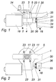
- the tube board 1 is screwed to the gear 20 by at least one screw 13.
- two screws 13 are arranged symmetrically to the left and right of the drive shaft 4, which can reach completely through the tube plate 1, as shown, or only through the lower part 27 of the tube plate 1.
- the bearing socket 3 is positively fixed in the tubular element 5 in the axial direction 10 with a locking ring 15 or another locking element, for example with a so-called speed groove.
- the bearing socket 3 is biased against the tubular element 5 with a spring 14 in the axial direction 10.
- a plate spring 14 is plugged onto the bearing socket 3, which, after the bearing socket 3 has been inserted into the tubular element 5, is located between the lower annular collar 22 and the transmission 20 and one downward from the tubular element 5 pointing force 28 generated on the bearing neck 3.
- the movement of the bearing socket 3 out of the tubular element 5 is prevented by a securing ring 15 arranged on the top of the bearing socket 3, which is supported on the upper collar 21.
- the bearing socket 3 is axially fixed with a union nut 16. After insertion of the bearing socket 3 into the tubular element 5, this is screwed onto the bearing socket 3 from above, is supported on the upper collar 21 of the tubular element 5 and pulls the bearing socket 3 into the tubular element 5 from below then on the lower collar 22.
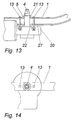
- the bearing socket 3 can be fixed in the axial direction 10 by a deformation 17 of the tubular element 5. This is achieved by the bearing socket 3 having a groove 29 into which the tubular element 5 is embossed or pressed. This is preferably done at 90 ° to the longitudinal direction of the tube plate 1.
- connection between the bearing socket 3 and the tubular element 5 is used for at least one further fastening point 18 on an adjacent component.
- This is preferably achieved with an attachment point 18 additionally attached to the transmission 20.
- a pin 31 is arranged on the end face 30 of the transmission 20 - e.g. by non-cutting or cutting, etc. - or welded, inserted, etc.
- an angle plate 32 is mounted on a buffer 33.
- the buffer 33 is introduced into a recess 34 in the angle plate 32 and is plugged into the pin 31 with a hole 35. With the angled end 36 of the angle plate 32 pointing away from the transmission 20, this is screwed or welded to an adjacent component, for example to a vehicle body.
- the additional attachment point 18 creates a stiffer support overall.
- the buffer 33 dampens oscillations and vibrations.
Landscapes
- Engineering & Computer Science (AREA)
- Mechanical Engineering (AREA)
- Support Of The Bearing (AREA)
- General Details Of Gearings (AREA)
- Motor Power Transmission Devices (AREA)
- Cleaning By Liquid Or Steam (AREA)
Applications Claiming Priority (4)
| Application Number | Priority Date | Filing Date | Title |
|---|---|---|---|
| DE19611919 | 1996-03-26 | ||
| DE19611919 | 1996-03-26 | ||
| DE19642667A DE19642667A1 (de) | 1996-03-26 | 1996-10-16 | Lagerung eines Wischerantriebs |
| DE19642667 | 1996-10-16 |
Publications (2)
| Publication Number | Publication Date |
|---|---|
| EP0798181A1 true EP0798181A1 (fr) | 1997-10-01 |
| EP0798181B1 EP0798181B1 (fr) | 2002-03-27 |
Family
ID=26024139
Family Applications (1)
| Application Number | Title | Priority Date | Filing Date |
|---|---|---|---|
| EP96120307A Expired - Lifetime EP0798181B1 (fr) | 1996-03-26 | 1996-12-18 | Palier d'entraínement d'un essuie-glace |
Country Status (3)
| Country | Link |
|---|---|
| US (1) | US5878631A (fr) |
| EP (1) | EP0798181B1 (fr) |
| ES (1) | ES2175017T3 (fr) |
Cited By (4)
| Publication number | Priority date | Publication date | Assignee | Title |
|---|---|---|---|---|
| FR2776604A1 (fr) * | 1998-03-30 | 1999-10-01 | Valeo Systemes Dessuyage | Systeme d'essuyage comportant une traverse tubulaire |
| WO2000005110A1 (fr) * | 1998-07-23 | 2000-02-03 | Robert Bosch Gmbh | Platine tubulaire pour systeme d'essuie-glace |
| WO2001025065A1 (fr) * | 1999-10-04 | 2001-04-12 | Valeo Auto-Electric Wischer Und Motoren Gmbh | Dispositif d'essuie-glace |
| US6438815B1 (en) * | 1996-03-18 | 2002-08-27 | Volkswagen Ag | Windshield wiper arrangement for vehicles |
Families Citing this family (10)
| Publication number | Priority date | Publication date | Assignee | Title |
|---|---|---|---|---|
| ES2177712T3 (es) * | 1996-03-26 | 2002-12-16 | Bosch Gmbh Robert | Pieza tubular moldeada de soporte. |
| DE19735818C2 (de) * | 1997-08-18 | 1999-10-21 | Daimler Chrysler Ag | Befestigungsvorrichtung für eine Scheibenwischeranlage eines Kraftfahrzeuges |
| JP3729635B2 (ja) * | 1998-03-30 | 2005-12-21 | 自動車電機工業株式会社 | ワイパユニット |
| DE19820789A1 (de) * | 1998-05-09 | 1998-12-03 | Detlef Brommer | Kontrollverfahren für Werkstücke in der Industrie, exakte Kontrolle der Richtigkeit, Vollzähligkeit, Lage, Anordnung und evtl. Beschädigungen von Werkstücken, Maschinen- und Motorenteilen i. d. industriellen Fertigung |
| JP3492938B2 (ja) * | 1998-08-27 | 2004-02-03 | アスモ株式会社 | ワイパ装置 |
| US6270142B1 (en) * | 1999-10-08 | 2001-08-07 | Jay D. Danielsen | Motorcycle windshield wiper |
| DE10039293A1 (de) * | 2000-08-11 | 2002-06-20 | Valeo Auto Electric Gmbh | Wischvorrichtung, insbesondere für Kraftfahrzeuge sowie Verfahren zum Befestigen einer Scheibenwischanlage |
| DE10205019A1 (de) * | 2002-02-07 | 2003-08-21 | Bosch Gmbh Robert | Scheibenwischvorrichtung |
| EP1597119A1 (fr) * | 2003-02-04 | 2005-11-23 | Commercial Vehicle Systems, Inc. | Ensemble d'essuie-glace et procede pour former ledit ensemble |
| DE10329266A1 (de) * | 2003-06-30 | 2005-01-20 | Robert Bosch Gmbh | Scheibenwischvorrichtung, insbesondere für ein Kraftfahrzeug |
Citations (4)
| Publication number | Priority date | Publication date | Assignee | Title |
|---|---|---|---|---|
| EP0147782A2 (fr) * | 1984-01-04 | 1985-07-10 | Bayerische Motoren Werke Aktiengesellschaft, Patentabteilung AJ-3 | Arrangement d'essuie-glace notamment arrangement d'essuie à bras unique gouvernable pour véhicules automobiles |
| FR2667833A1 (fr) * | 1990-10-10 | 1992-04-17 | Valeo Systemes Dessuyage | Platine de support d'un moteur d'entrainement, notamment de moto-reducteur d'essuyage. |
| DE4333484A1 (de) * | 1992-10-30 | 1994-05-05 | Asmo Co Ltd | Wischeranordnung |
| EP0739793A1 (fr) * | 1995-04-28 | 1996-10-30 | Valeo Systemes D'essuyage | Mécanisme d'essuie glace pour véhicule automobile comportant un élément de structure démontable |
Family Cites Families (7)
| Publication number | Priority date | Publication date | Assignee | Title |
|---|---|---|---|---|
| US1998760A (en) * | 1931-05-11 | 1935-04-23 | Trico Products Corp | Combined windshield and cleaner therefor |
| DE3903976C2 (de) * | 1989-02-10 | 1997-07-03 | Teves Gmbh Alfred | Wischeranlage |
| US5074613A (en) * | 1989-12-01 | 1991-12-24 | General Motors Corporation | Vehicle windshield wiper system with improved housing to frame connection |
| JPH086641Y2 (ja) * | 1990-11-02 | 1996-02-28 | 株式会社三ツ葉電機製作所 | パイプ式モジユラワイパ装置のパイプ締結構造 |
| JP2544115Y2 (ja) * | 1991-07-30 | 1997-08-13 | 株式会社ミツバ | モジユラ型ワイパ装置の躯体取付け構造 |
| JP3964463B2 (ja) * | 1996-03-18 | 2007-08-22 | フオルクスワーゲン・アクチエンゲゼルシヤフト | 乗物用の風防ガラスのワイパー装置とその作製方法 |
| US5647086A (en) * | 1996-10-22 | 1997-07-15 | Gold; Peter | Spare wheel carrier-mounted rear window wiper |
-
1996
- 1996-12-18 ES ES96120307T patent/ES2175017T3/es not_active Expired - Lifetime
- 1996-12-18 EP EP96120307A patent/EP0798181B1/fr not_active Expired - Lifetime
-
1997
- 1997-02-21 US US08/806,260 patent/US5878631A/en not_active Expired - Fee Related
Patent Citations (4)
| Publication number | Priority date | Publication date | Assignee | Title |
|---|---|---|---|---|
| EP0147782A2 (fr) * | 1984-01-04 | 1985-07-10 | Bayerische Motoren Werke Aktiengesellschaft, Patentabteilung AJ-3 | Arrangement d'essuie-glace notamment arrangement d'essuie à bras unique gouvernable pour véhicules automobiles |
| FR2667833A1 (fr) * | 1990-10-10 | 1992-04-17 | Valeo Systemes Dessuyage | Platine de support d'un moteur d'entrainement, notamment de moto-reducteur d'essuyage. |
| DE4333484A1 (de) * | 1992-10-30 | 1994-05-05 | Asmo Co Ltd | Wischeranordnung |
| EP0739793A1 (fr) * | 1995-04-28 | 1996-10-30 | Valeo Systemes D'essuyage | Mécanisme d'essuie glace pour véhicule automobile comportant un élément de structure démontable |
Cited By (5)
| Publication number | Priority date | Publication date | Assignee | Title |
|---|---|---|---|---|
| US6438815B1 (en) * | 1996-03-18 | 2002-08-27 | Volkswagen Ag | Windshield wiper arrangement for vehicles |
| FR2776604A1 (fr) * | 1998-03-30 | 1999-10-01 | Valeo Systemes Dessuyage | Systeme d'essuyage comportant une traverse tubulaire |
| WO2000005110A1 (fr) * | 1998-07-23 | 2000-02-03 | Robert Bosch Gmbh | Platine tubulaire pour systeme d'essuie-glace |
| WO2001025065A1 (fr) * | 1999-10-04 | 2001-04-12 | Valeo Auto-Electric Wischer Und Motoren Gmbh | Dispositif d'essuie-glace |
| US6959621B1 (en) | 1999-10-04 | 2005-11-01 | Valeo Auto-Electric Wischer Und Motoren Gmbh | Wiping device |
Also Published As
| Publication number | Publication date |
|---|---|
| US5878631A (en) | 1999-03-09 |
| EP0798181B1 (fr) | 2002-03-27 |
| ES2175017T3 (es) | 2002-11-16 |
Similar Documents
| Publication | Publication Date | Title |
|---|---|---|
| DE102006004678B4 (de) | Montageeinheit für die Befestigungsöse eines Gurtschlosses | |
| EP1713669B1 (fr) | Dispositif d'essuie-glace, en particulier pour vehicule a moteur | |
| EP1291254B1 (fr) | Dispositif d'essuie-glace | |
| EP0799142B1 (fr) | Systeme d'essuie-glaces pourvu d'un element de fixation amortissant le bruit et les vibrations | |
| EP0798181B1 (fr) | Palier d'entraínement d'un essuie-glace | |
| EP0779452A2 (fr) | Dispositif de tension de courroie | |
| EP1458596B1 (fr) | Fixation d'un systeme d'essuie-glace | |
| EP1076620A1 (fr) | Dispositif pour fixer un levier de commande sur un arbre | |
| EP1721084B1 (fr) | Systeme bielle-manivelle et piece usinee pour un systeme bielle-manivelle | |
| EP2019765B1 (fr) | Dispositif et procédé pour fixer un moteur d'essuie-glace sur une tringlerie d'essuie-glace | |
| EP0572821B1 (fr) | Colonne de direction de voiture | |
| EP0798182B1 (fr) | Palier pour arbre d'entraínement d'un dispositif d'essuie-glace | |
| DE102007029410B4 (de) | Befestigungsklammer | |
| DE19642667A1 (de) | Lagerung eines Wischerantriebs | |
| EP2006171A2 (fr) | Dispositif d'entraînement d'essuie-glace | |
| EP2072358A2 (fr) | Palier d'essuie-glace | |
| DE102004049186A1 (de) | Lageranordnung für eine Zwischenwelle | |
| DE102005063019B4 (de) | Lagerung einer Motor-Getriebe-Einheit einer Wischeranlage an einem Träger | |
| DE10208538B4 (de) | Wischeranlage mit einer Platine | |
| EP2102038A1 (fr) | Ensemble boîtier d'un système essuie-glace à assemblage vissé | |
| DE102008041264A1 (de) | Scheibenwischervorrichtung für ein Kraftfahrzeug | |
| DE102004007517A1 (de) | Scheibenwischvorrichtung, insbesondere für ein Kraftfahrzeug | |
| DE202006019860U1 (de) | Scheibenwischerantriebsanordnung | |
| DE10232877A1 (de) | Scheibenwischvorrichtung, insbesondere für ein Kraftfahrzeug | |
| DE102018212336A1 (de) | Wischanlage |
Legal Events
| Date | Code | Title | Description |
|---|---|---|---|
| PUAI | Public reference made under article 153(3) epc to a published international application that has entered the european phase |
Free format text: ORIGINAL CODE: 0009012 |
|
| AK | Designated contracting states |
Kind code of ref document: A1 Designated state(s): DE ES FR GB IT |
|
| 17P | Request for examination filed |
Effective date: 19980401 |
|
| 17Q | First examination report despatched |
Effective date: 19991025 |
|
| GRAG | Despatch of communication of intention to grant |
Free format text: ORIGINAL CODE: EPIDOS AGRA |
|
| GRAG | Despatch of communication of intention to grant |
Free format text: ORIGINAL CODE: EPIDOS AGRA |
|
| GRAH | Despatch of communication of intention to grant a patent |
Free format text: ORIGINAL CODE: EPIDOS IGRA |
|
| GRAH | Despatch of communication of intention to grant a patent |
Free format text: ORIGINAL CODE: EPIDOS IGRA |
|
| REG | Reference to a national code |
Ref country code: GB Ref legal event code: IF02 |
|
| GRAA | (expected) grant |
Free format text: ORIGINAL CODE: 0009210 |
|
| AK | Designated contracting states |
Kind code of ref document: B1 Designated state(s): DE ES FR GB IT |
|
| REF | Corresponds to: |
Ref document number: 59608961 Country of ref document: DE Date of ref document: 20020502 |
|
| ET | Fr: translation filed | ||
| REG | Reference to a national code |
Ref country code: ES Ref legal event code: FG2A Ref document number: 2175017 Country of ref document: ES Kind code of ref document: T3 |
|
| PLBE | No opposition filed within time limit |
Free format text: ORIGINAL CODE: 0009261 |
|
| STAA | Information on the status of an ep patent application or granted ep patent |
Free format text: STATUS: NO OPPOSITION FILED WITHIN TIME LIMIT |
|
| 26N | No opposition filed |
Effective date: 20021230 |
|
| PGFP | Annual fee paid to national office [announced via postgrant information from national office to epo] |
Ref country code: GB Payment date: 20041207 Year of fee payment: 9 |
|
| PGFP | Annual fee paid to national office [announced via postgrant information from national office to epo] |
Ref country code: FR Payment date: 20041221 Year of fee payment: 9 |
|
| PGFP | Annual fee paid to national office [announced via postgrant information from national office to epo] |
Ref country code: ES Payment date: 20041228 Year of fee payment: 9 |
|
| PGFP | Annual fee paid to national office [announced via postgrant information from national office to epo] |
Ref country code: DE Payment date: 20050208 Year of fee payment: 9 |
|
| PG25 | Lapsed in a contracting state [announced via postgrant information from national office to epo] |
Ref country code: IT Free format text: LAPSE BECAUSE OF NON-PAYMENT OF DUE FEES Effective date: 20051218 Ref country code: GB Free format text: LAPSE BECAUSE OF NON-PAYMENT OF DUE FEES Effective date: 20051218 |
|
| PG25 | Lapsed in a contracting state [announced via postgrant information from national office to epo] |
Ref country code: ES Free format text: LAPSE BECAUSE OF NON-PAYMENT OF DUE FEES Effective date: 20051219 |
|
| PG25 | Lapsed in a contracting state [announced via postgrant information from national office to epo] |
Ref country code: DE Free format text: LAPSE BECAUSE OF NON-PAYMENT OF DUE FEES Effective date: 20060701 |
|
| GBPC | Gb: european patent ceased through non-payment of renewal fee |
Effective date: 20051218 |
|
| PG25 | Lapsed in a contracting state [announced via postgrant information from national office to epo] |
Ref country code: FR Free format text: LAPSE BECAUSE OF NON-PAYMENT OF DUE FEES Effective date: 20060831 |
|
| REG | Reference to a national code |
Ref country code: FR Ref legal event code: ST Effective date: 20060831 |
|
| REG | Reference to a national code |
Ref country code: ES Ref legal event code: FD2A Effective date: 20051219 |