EP1721084B1 - Systeme bielle-manivelle et piece usinee pour un systeme bielle-manivelle - Google Patents
Systeme bielle-manivelle et piece usinee pour un systeme bielle-manivelle Download PDFInfo
- Publication number
- EP1721084B1 EP1721084B1 EP05716602A EP05716602A EP1721084B1 EP 1721084 B1 EP1721084 B1 EP 1721084B1 EP 05716602 A EP05716602 A EP 05716602A EP 05716602 A EP05716602 A EP 05716602A EP 1721084 B1 EP1721084 B1 EP 1721084B1
- Authority
- EP
- European Patent Office
- Prior art keywords
- shaft
- crank
- structural part
- crankshaft arrangement
- molded part
- Prior art date
- Legal status (The legal status is an assumption and is not a legal conclusion. Google has not performed a legal analysis and makes no representation as to the accuracy of the status listed.)
- Expired - Fee Related
Links
Images


Classifications
-
- B—PERFORMING OPERATIONS; TRANSPORTING
- B60—VEHICLES IN GENERAL
- B60S—SERVICING, CLEANING, REPAIRING, SUPPORTING, LIFTING, OR MANOEUVRING OF VEHICLES, NOT OTHERWISE PROVIDED FOR
- B60S1/00—Cleaning of vehicles
- B60S1/02—Cleaning windscreens, windows or optical devices
- B60S1/04—Wipers or the like, e.g. scrapers
- B60S1/06—Wipers or the like, e.g. scrapers characterised by the drive
- B60S1/16—Means for transmitting drive
- B60S1/18—Means for transmitting drive mechanically
- B60S1/24—Means for transmitting drive mechanically by rotary cranks
-
- B—PERFORMING OPERATIONS; TRANSPORTING
- B60—VEHICLES IN GENERAL
- B60S—SERVICING, CLEANING, REPAIRING, SUPPORTING, LIFTING, OR MANOEUVRING OF VEHICLES, NOT OTHERWISE PROVIDED FOR
- B60S1/00—Cleaning of vehicles
- B60S1/02—Cleaning windscreens, windows or optical devices
- B60S1/04—Wipers or the like, e.g. scrapers
- B60S1/06—Wipers or the like, e.g. scrapers characterised by the drive
-
- F—MECHANICAL ENGINEERING; LIGHTING; HEATING; WEAPONS; BLASTING
- F16—ENGINEERING ELEMENTS AND UNITS; GENERAL MEASURES FOR PRODUCING AND MAINTAINING EFFECTIVE FUNCTIONING OF MACHINES OR INSTALLATIONS; THERMAL INSULATION IN GENERAL
- F16C—SHAFTS; FLEXIBLE SHAFTS; ELEMENTS OR CRANKSHAFT MECHANISMS; ROTARY BODIES OTHER THAN GEARING ELEMENTS; BEARINGS
- F16C3/00—Shafts; Axles; Cranks; Eccentrics
- F16C3/04—Crankshafts, eccentric-shafts; Cranks, eccentrics
- F16C3/06—Crankshafts
- F16C3/10—Crankshafts assembled of several parts, e.g. by welding by crimping
- F16C3/12—Crankshafts assembled of several parts, e.g. by welding by crimping releasably connected
-
- F—MECHANICAL ENGINEERING; LIGHTING; HEATING; WEAPONS; BLASTING
- F16—ENGINEERING ELEMENTS AND UNITS; GENERAL MEASURES FOR PRODUCING AND MAINTAINING EFFECTIVE FUNCTIONING OF MACHINES OR INSTALLATIONS; THERMAL INSULATION IN GENERAL
- F16C—SHAFTS; FLEXIBLE SHAFTS; ELEMENTS OR CRANKSHAFT MECHANISMS; ROTARY BODIES OTHER THAN GEARING ELEMENTS; BEARINGS
- F16C2326/00—Articles relating to transporting
- F16C2326/01—Parts of vehicles in general
- F16C2326/09—Windscreen wipers, e.g. pivots therefore
-
- Y—GENERAL TAGGING OF NEW TECHNOLOGICAL DEVELOPMENTS; GENERAL TAGGING OF CROSS-SECTIONAL TECHNOLOGIES SPANNING OVER SEVERAL SECTIONS OF THE IPC; TECHNICAL SUBJECTS COVERED BY FORMER USPC CROSS-REFERENCE ART COLLECTIONS [XRACs] AND DIGESTS
- Y10—TECHNICAL SUBJECTS COVERED BY FORMER USPC
- Y10T—TECHNICAL SUBJECTS COVERED BY FORMER US CLASSIFICATION
- Y10T403/00—Joints and connections
- Y10T403/16—Joints and connections with adjunctive protector, broken parts retainer, repair, assembly or disassembly feature
Definitions
- the invention is based on a crankshaft arrangement and a shaped part for a crankshaft arrangement according to the preambles of claims 1 and 8.
- Crankshaft arrangements in particular for windscreen wiper systems, are known.
- For transmitting a torque from a drive unit to a crank has already been proposed to rivet the crank with a shaft or an axially mounted on a conical knurl of the shaft crank with the shaft by means of a nut to screw.
- the preparation of the compound requires a plurality of steps, such as tapping on the shaft, and a relatively large length of the shaft for tightening the nut.
- the shows WO 01/21460 A1 a drive shaft for a windshield wiper, to which a crank is attached. It is provided that a main body of the drive shaft is made of an extruded light metal profile and carries at its free end in the region of a fastening part a connecting part made of a harder material having a screw thread.
- a crankshaft arrangement in which a crank is connected via a separate molded part to a shaft, wherein the molded part has a web on its second end face.
- the molded part forms an intermediate piece between the crank and the shaft, in particular output shaft, of the engine.
- the shaft can not be supported on the drive gear when pressing the crank on the shaft.
- the molded part must transmit radial force, which can be ensured by a positive connection by pressing.
- the shaft may be formed as a smooth cylinder or as a polygonal element.
- the molded part can have an inner knurl of hardened or corresponding material, so that the knurl presses into the shaft.
- the shaft has a knurl on its outer side and impresses itself in the molding during pressing.
- shaft and molded part can form a toothing with each other.
- connection between crank and molded part A person skilled in the art will select a combination that makes sense to him for attachment.
- the molded part can be mounted independently of the crank on the shaft and secured axially on this.
- the fuse can be done by caulking, welding and the like.
- a support against a transmission housing or a bearing flange may be provided which keeps an axial load from the shaft and / or from a drive gear. When later attaching the crank on the molding can be ensured that the axial load on the shaft is practically negligible.
- the crank can be easily mounted on the shaft of a drive motor, if it is already installed in the wiper system.
- the shaft can be made shorter overall than in a conventional sterbefest Trent, additional steps for threading on the shaft can be omitted, and the drive motor is protected against axial load.
- a favorable axial fixation of the crank on the molding is to provide the molding at its first end face with a radially outwardly foldable edge.
- the edge projects axially away from the first end face.
- the edge overlaps the crank in the region of the bore, so that the crank is axially fixed on the molded part and thus on the shaft.
- the shaft at its end facing the molding thread with a predetermined breaking point for separating the thread from the shaft, the folding of the edge can be done in a particularly simple and reliable manner by a nut is screwed.
- the molded part can be pressed over the thread by screwing the nut with the crank, without the transmission housing or the bearing have to absorb a force.
- crank A simple connection of the crank to the molded part is possible when the molded part projects with its first end face into a bore of the crank.
- the crank can be secured axially in a variety of ways on the molded part, such as by welding, notches, tumbling, by a locking ring, a so-called speed groove and the like.
- the type of backup can be selected as needed.
- a shaft gentle assembly of the crank is when the molding has at its second end face the web for support on a counter-bearing.
- the anvil can e.g. a transmission housing or a bearing flange of an eccentric bushing, on which the crankshaft assembly is arranged.
- the molded part is supported on the counter bearing, and the crank can be pressed onto the molded part, without the shaft being axially loaded.
- the web forms a bottom of a sleeve extending in the axial direction away from the first and second end surfaces.
- a body lying within the sleeve, such as a bearing flange or a gear housing can be protected from splash water. This is particularly advantageous in windscreen wiper systems. A separate water protection and its fasteners can be omitted.
- the usually round shaft may have at its projecting into a bore of the molding end a plane surface or an edge and the molding a corresponding plane surface or edge in its bore.
- a polygonal contour or a knurled contour of the shaft wherein the knurl has a plurality of teeth, with a corresponding configuration of the bore of the crank, so that a rotation is ensured.
- the molded part may have a cylindrical outer wall or, alternatively, an outer wall which tapers towards the first end face, wherein the outer wall may be smooth or polygonal or knurled.
- a molded part for a crankshaft device for connecting a crank to a shaft wherein a sleeve of the molded part has a web on one of its end faces.
- the sleeve should have on its one end face opposite end side in the radial direction outwardly foldable edge.
- the bridge ensures that when mounting the crank axial load on the shaft is minimized.
- An attachment of the crank on the shaft can be done independently of the attachment of the molding on the shaft.
- the sleeve has on its one end face opposite end side in the radial direction outwardly foldable edge, so that the crank can be secured axially by simply flipping the edge on the molding.
- a splash guard can be integrated into the molded part in a simple manner, when the web forms a bottom of a sleeve extending in the axial direction away from the end faces. Within this sleeve lying elements are largely protected from splash water.
- the crankshaft device is particularly suitable for a windshield wiper system in which a shaft of a drive motor is in drive connection with a crank for driving a wiper element.
- Fig. 1 a shows a longitudinal section through a preferred embodiment of a crankshaft device according to the invention.
- the shaft 10 protrudes through a drive gear 50, a gear housing 48 and an eccentric bushing 46 in a bore 14 of a crank 12. Between the drive gear 50 and the eccentric bushing 46, a spring washer 64 is arranged.
- the shaft 10 terminates in a polygonal element 36 designed as a knurl, which may be an integral part of the shaft 10 or which is fixedly connected thereto, in particular pressed onto the shaft 10.
- a sleeve 18 of a molded part 16 is pressed.
- the molding 16 protrudes with its first end face 24 into the bore 14 of the crank 12.
- the bore 14 is suitably adapted to the shape of the outer wall 20 of the molded part 16.
- a web 30, designed in particular as a peripheral gutter is arranged, with which the molded part 16 is seated on the eccentric bushing 46 as an abutment.
- the crank 12 is pressed, which thus on the molding 16 with the Polygonal element 36 and thus connected to the shaft 10.
- the crank 12 is secured axially on the molding 16 by a fixation 62, for example a weld.
- the web 30 forms according to a preferred embodiment, a bottom 32 of a in the axial direction 38 of the first and second end face 24, 26 extending away sleeve 34 and acts as a splash guard for the eccentric bushing 46 and the transmission housing 48th
- FIG. 1 b An alternative attachment of the molding 16 on the shaft 10 and the polygonal element 36 shows the Fig. 1 b that only made up a section of the arrangement Fig. 1 a shows.
- the arrangement largely corresponds to that in Fig. 1 a.
- a polygonal element 66 designed as a knurl is arranged between the outer wall of the molded part 16 projecting into its bore 14 and the bore 14 of the crank 12.
- the molded part 16 is secured with a notch 67 axially on the shaft 10 and the polygonal element 36.
- the eccentric bushing 46 is conical, and the transmission housing 56 has a correspondingly adapted opening.
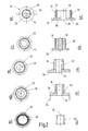
- FIG Fig. 2 al A plan view and a section through various preferred embodiments of a molding 16 is shown in FIG Fig. 2 al shown.
- the supervision on in Fig. 2a can be seen in the center of a shaft 10, which is formed as a square.
- the shaft 10 is surrounded by a molded part 16 whose outer wall 20 forms a polygonal element 36 formed as a knurl.
- the cut in Fig. 2b shows the shaft 10 in the center of the molding 16 and the outer wall 20 of the molding 16, which has at its second end face 26 has a web 30 for support on an abutment.
- Fig. 2 al shows the shaft 10 in the center of the molding 16 and the outer wall 20 of the molding 16, which has at its second end face 26 has a web 30 for support on an abutment.
- FIGS. 2e and 2f shows a plan view and a section with a cylindrical shaft 10.
- Die Fig. 2g and 2h shows a plan view and a section with an outer wall formed as an outer wall 20 of the shaft 10 and a molded part 16 with inner and outer knurl.
- the molding 16 here optionally has a sleeve 34 as Splash protection, which can be provided on all molded part designs shown here.
- 2k and 2l shows a plan view and a section with a molding 16, the inner bore is deep drawn and forms an inner and outer knurl, wherein the shaft 10 has an outer knurl.
- an outwardly umlegbarer edge can be provided on the molding 16, as later in the Fig. 4 and 5 is described.
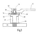
- a prior art crankshaft assembly shows for comparison FIG. 3 ,
- a crank 12 surrounds with its bore 14 a conical knurl 58 which sits on a shaft 10 of a drive motor, not shown.
- grooves 54 are arranged, which serve for fastening a locking element 60 (speed groove) on an eccentric bush 46 connected to a gear housing 48.
- a pot-shaped element 56 is arranged as a spray water protection, which covers the upper region of the eccentric bushing 46.
- the crank 12 is secured axially on the shaft 10 by a screwed fastening nut 52 which is screwed onto a thread of the shaft 10.
- the crankshaft device according to the prior art has by fastening nut 52 a greater height, while the crankshaft device according to the invention builds much smaller.
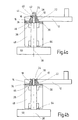
- Fig. 4 a, b shows a preferred embodiment of a crankshaft device with foldable edge 28 before (a) and after (b) the folding of the edge 28 with a molded part 16.
- a shaft 10 is performed by a drive gear 50, a gear housing 48, an eccentric bushing 46 and the molding 16 and ends in a polygonal element 36.
- the polygonal element 36 is fixedly connected to the shaft 10, for example, pressed on, or integrally formed therewith.
- the molded part 16 tapers toward its first end face 24 and is in particular conically shaped. It has an inner bore adapted to the polygonal element 36, so that an anti-twist protection is ensured.
- the radially outwardly foldable edge 28 is arranged on the first end face 24 of the molded part 16.
- a web 30 surrounding the lower region of its outer wall 22 is arranged, with which the molded part 16 is supported on the eccentric bushing 46.
- the shaft 10 has a thread 42 with a predetermined breaking point 44 for separating the thread 42 of the shaft 10.
- the crank 12 can be mounted on the molding 16.
- a nut not shown in the drawing can be screwed onto the thread 42, which first presses the crank 12 on the mold part 16 when tightening and then on further tightening the Edge 28 displaced to the outside.
- the nut can be tightened until the thread breaks off 42 at the predetermined breaking point 44 and the arrangement reaches its advantageous low height.
- This state shows Fig. 4b ,
- Fig. 5 a, b shows a further preferred embodiment of a crankshaft device with foldable edge 28 before (a) and after (b) the folding of the edge 28 with a molded part 16 with a cylindrical outer wall 20.
- the arrangement corresponds to the in Fig. 4 , And the axial securing of the crank 12 in the same manner as shown there. For description will be on the Fig. 4 directed.
Landscapes
- Engineering & Computer Science (AREA)
- General Engineering & Computer Science (AREA)
- Mechanical Engineering (AREA)
- Ocean & Marine Engineering (AREA)
- Shafts, Cranks, Connecting Bars, And Related Bearings (AREA)
Abstract
Claims (9)
- Système bielle-manivelle, en particulier pour un bras d'essuie-glace, dans lequel un arbre (10) est en liaison d'entraînement avec une manivelle (12), la manivelle (12) étant connectée à l'arbre (10) par le biais d'une pièce moulée séparée (16), la pièce moulée (16) présentant sur sa deuxième face frontale (26) une nervure (30), caractérisé en ce que la pièce moulée (16) présente sur sa première face frontale (24) un bord (28) pouvant être recourbé vers l'extérieur dans la direction radiale.
- Système bielle-manivelle selon la revendication 1, caractérisé en ce que la pièce moulée (16) pénètre avec sa première face frontale (24) dans un alésage (14) de la manivelle (12).
- Système bielle-manivelle selon la revendication 1 ou 2, caractérisé en ce que la pièce moulée (16) présente, sur sa deuxième face frontale (26), la nervure (30) pour le support sur un palier conjugué.
- Système bielle-manivelle selon l'une quelconque des revendications 1 à 3, caractérisé en ce que la nervure (30) forme un fond d'une douille (34) s'étendant à l'écart de la première et de la deuxième face frontale (24, 26) dans la direction axiale (38).
- Système bielle-manivelle selon l'une quelconque des revendications précédentes, caractérisé en ce que la pièce moulée (16) est connectée à l'arbre (10) au moins de manière imperdable.
- Système bielle-manivelle selon l'une quelconque des revendications précédentes, caractérisé en ce que la pièce moulée (16) présente une paroi extérieure cylindrique (20).
- Système bielle-manivelle selon l'une quelconque des revendications 2 à 6, caractérisé en ce que la pièce moulée (16) présente une paroi extérieure (22) qui se rétrécit vers la première face frontale (24).
- Pièce moulée pour un système bielle-manivelle pour connecter une manivelle (12) à un arbre (10), une douille (18) de la pièce moulée présentant sur l'un de ses côtés frontaux (26) une nervure (30), caractérisée en ce que la douille (18) présente sur son côté frontal (24) opposé au premier côté frontal (26), un bord (28) pouvant être recourbé vers l'extérieur dans la direction radiale.
- Pièce moulée selon la revendication 8, caractérisée en ce que la nervure (30) forme un fond (32) d'une douille (34) s'étendant à l'écart des faces frontales (24, 26) dans la direction axiale (38).
Applications Claiming Priority (2)
| Application Number | Priority Date | Filing Date | Title |
|---|---|---|---|
| DE102004009717A DE102004009717A1 (de) | 2004-02-27 | 2004-02-27 | Kurbelwellenanordnung und Formteil für eine Kurbelwellenanordnung |
| PCT/EP2005/050364 WO2005083279A1 (fr) | 2004-02-27 | 2005-01-28 | Systeme bielle-manivelle et piece usinee pour un systeme bielle-manivelle |
Publications (2)
| Publication Number | Publication Date |
|---|---|
| EP1721084A1 EP1721084A1 (fr) | 2006-11-15 |
| EP1721084B1 true EP1721084B1 (fr) | 2011-03-23 |
Family
ID=34853799
Family Applications (1)
| Application Number | Title | Priority Date | Filing Date |
|---|---|---|---|
| EP05716602A Expired - Fee Related EP1721084B1 (fr) | 2004-02-27 | 2005-01-28 | Systeme bielle-manivelle et piece usinee pour un systeme bielle-manivelle |
Country Status (9)
| Country | Link |
|---|---|
| US (1) | US20070158396A1 (fr) |
| EP (1) | EP1721084B1 (fr) |
| JP (1) | JP4637101B2 (fr) |
| KR (1) | KR101132604B1 (fr) |
| CN (1) | CN1926347B (fr) |
| BR (1) | BRPI0506143A (fr) |
| DE (2) | DE102004009717A1 (fr) |
| ES (1) | ES2360406T3 (fr) |
| WO (1) | WO2005083279A1 (fr) |
Families Citing this family (9)
| Publication number | Priority date | Publication date | Assignee | Title |
|---|---|---|---|---|
| DE102006013161A1 (de) * | 2006-03-22 | 2007-09-27 | Robert Bosch Gmbh | Elektromotor, insbesondere Wischermotor für Kraftfahrzeuge, mit einer Excenterbuchse |
| JP4847388B2 (ja) * | 2007-04-09 | 2011-12-28 | 株式会社コロナ | 温風暖房機 |
| DE102007062168A1 (de) | 2007-12-21 | 2009-06-25 | Robert Bosch Gmbh | Gehäuse mit einer Abtriebswelle und Verfahren zum Befestigen eines Mittels an einer Abtriebswelle |
| JP5383311B2 (ja) * | 2008-05-20 | 2014-01-08 | アスモ株式会社 | ワイパモータ及びワイパ装置 |
| US9017017B2 (en) * | 2009-04-10 | 2015-04-28 | Honeywell Internatonal Inc. | Variable-vane assembly having fixed guide pins for unison ring |
| DE102013202342B4 (de) | 2013-02-13 | 2015-10-15 | Continental Automotive Gmbh | Verfahren zum Einstellen eines Axialspiels eines in einem Lager gelagerten Zapfens und Vorrichtung umfassend ein Lager und einen in dem Lager gelagerten Zapfen |
| DE102014203217A1 (de) * | 2014-02-24 | 2015-08-27 | Robert Bosch Gmbh | Antriebseinrichtung für eine Scheibenwischvorrichtung |
| CN105240395B (zh) * | 2014-06-24 | 2018-12-18 | 定远县众创科技服务有限公司 | 一种旋转半径可变偏心轴 |
| CN109823309A (zh) * | 2019-03-13 | 2019-05-31 | 王现思 | 用于雨刮器的枢转组合件以及雨刮器 |
Family Cites Families (17)
| Publication number | Priority date | Publication date | Assignee | Title |
|---|---|---|---|---|
| US2741932A (en) * | 1952-04-23 | 1956-04-17 | Isthmian Metals Inc | Crankshaft and method of making the same |
| US3039798A (en) * | 1959-07-20 | 1962-06-19 | Gen Motors Corp | Crank assembly and method of attaching cylindrical member to shaft |
| US3445145A (en) * | 1967-11-22 | 1969-05-20 | Eltra Corp | Two-piece journal bearing |
| DE2647510A1 (de) * | 1976-10-21 | 1978-04-27 | Daimler Benz Ag | Kurbel zum antrieb eines scheibenwischergestaenges |
| JPS6088663A (ja) * | 1983-10-19 | 1985-05-18 | Nippon Denso Co Ltd | ワイパリンクのピボツト装置 |
| DE3347433A1 (de) * | 1983-12-29 | 1985-07-11 | Heinrich Kipp Werk, 7247 Sulz | Handhebel |
| DE3738924A1 (de) * | 1987-11-17 | 1989-06-01 | Swf Auto Electric Gmbh | Getriebeteil fuer eine wischanlage von kraftfahrzeugen und verfahren zu dessen herstellen |
| FR2716658B1 (fr) * | 1994-02-28 | 1996-04-19 | Valeo Systemes Dessuyage | Dispositif d'essuie-glace comportant des moyens perfectionnés d'accouplement entre l'arbre moteur et la tête d'entraînement. |
| CH688786A5 (de) * | 1994-10-18 | 1998-03-13 | Fernand Moser | Handkurbel oder Handrad zur Befestigung auf einer Welle. |
| US6138320A (en) * | 1995-03-27 | 2000-10-31 | Asmo Co., Ltd. | Wiper pivot shaft and wiper apparatus |
| DE19804135B4 (de) * | 1998-02-03 | 2011-06-30 | Robert Bosch GmbH, 70469 | Wischerlager |
| JP3492938B2 (ja) * | 1998-08-27 | 2004-02-03 | アスモ株式会社 | ワイパ装置 |
| DE19908639A1 (de) * | 1999-02-27 | 2000-08-31 | Bosch Gmbh Robert | Wischerlager |
| DE19945091A1 (de) * | 1999-09-21 | 2001-04-19 | Bosch Gmbh Robert | Antriebswelle für einen Scheibenwischer |
| DE19950739A1 (de) * | 1999-10-21 | 2001-05-10 | Bosch Gmbh Robert | Wischerlager für eine Wischvorrichtung eines Fahrzeugs und Verfahren zum Montieren eines Wischerlagers |
| DE10154640A1 (de) * | 2001-11-07 | 2003-05-15 | Bosch Gmbh Robert | Scheibenwischvorrichtung, insbesondere für ein Kraftfahrzeug |
| JP2004314953A (ja) * | 2003-04-18 | 2004-11-11 | Johnson Electric Sa | ワイパー機構 |
-
2004
- 2004-02-27 DE DE102004009717A patent/DE102004009717A1/de not_active Withdrawn
-
2005
- 2005-01-28 CN CN2005800062685A patent/CN1926347B/zh not_active Expired - Fee Related
- 2005-01-28 JP JP2006521593A patent/JP4637101B2/ja not_active Expired - Fee Related
- 2005-01-28 KR KR1020067017175A patent/KR101132604B1/ko active IP Right Grant
- 2005-01-28 EP EP05716602A patent/EP1721084B1/fr not_active Expired - Fee Related
- 2005-01-28 ES ES05716602T patent/ES2360406T3/es active Active
- 2005-01-28 WO PCT/EP2005/050364 patent/WO2005083279A1/fr active Application Filing
- 2005-01-28 US US10/588,841 patent/US20070158396A1/en not_active Abandoned
- 2005-01-28 DE DE502005011157T patent/DE502005011157D1/de active Active
- 2005-01-28 BR BRPI0506143-1A patent/BRPI0506143A/pt not_active IP Right Cessation
Also Published As
| Publication number | Publication date |
|---|---|
| KR20060124728A (ko) | 2006-12-05 |
| JP4637101B2 (ja) | 2011-02-23 |
| EP1721084A1 (fr) | 2006-11-15 |
| CN1926347B (zh) | 2010-05-05 |
| DE102004009717A1 (de) | 2005-09-15 |
| WO2005083279A1 (fr) | 2005-09-09 |
| JP2006528755A (ja) | 2006-12-21 |
| BRPI0506143A (pt) | 2006-10-24 |
| DE502005011157D1 (de) | 2011-05-05 |
| US20070158396A1 (en) | 2007-07-12 |
| CN1926347A (zh) | 2007-03-07 |
| KR101132604B1 (ko) | 2012-04-06 |
| ES2360406T3 (es) | 2011-06-03 |
Similar Documents
| Publication | Publication Date | Title |
|---|---|---|
| EP1721084B1 (fr) | Systeme bielle-manivelle et piece usinee pour un systeme bielle-manivelle | |
| EP1713668B1 (fr) | Dispositif d'essuie-glace notamment destine a un vehicule | |
| EP1875090B1 (fr) | Procede pour loger un arbre et disposition de palier | |
| EP1718507B1 (fr) | Systeme d'essuie-glaces pour vehicules et element de fixation pour un systeme de ce type | |
| EP1837256B1 (fr) | Dispositif d'engrenage d'essuie-glace | |
| EP2902303A1 (fr) | Faux-châssis pour un véhicule automobile, notamment faux-châssis d'essieu avant et carrosserie dotée d'un tel faux-châssis | |
| EP1458596B1 (fr) | Fixation d'un systeme d'essuie-glace | |
| EP1075402B1 (fr) | Palier d'essuie-glace | |
| EP0798181A1 (fr) | Palier d'entraînement d'un essuie-glace | |
| EP1137558B1 (fr) | Dispositif pour fixer un bras d'essuie-glace sur un arbre de commande | |
| EP0952939A1 (fr) | Dispositif d'entrainement d'un systeme d'essuie-glace, notamment pour des vitres de vehicule | |
| EP2072358B1 (fr) | Palier d'essuie-glace | |
| EP0918931B1 (fr) | Groupe motopompe electrique | |
| EP1716026B1 (fr) | Dispositif essuie-glace | |
| DE10259956B4 (de) | Scheibenwischvorrichtung, insbesondere für ein Kraftfahrzeug | |
| EP2147837A1 (fr) | Entraînement d'essuie-glace | |
| EP1444118B1 (fr) | Systeme d'essuie-glace, destine en particulier a un vehicule automobile | |
| DE60107178T2 (de) | Elastisches Gelenk für einen Stossdämpfer and Stossdämpfer mit einem solchen Gelenk | |
| EP2102038B1 (fr) | Ensemble boîtier d'un système essuie-glace à assemblage vissé | |
| DE102004009302B4 (de) | Scheibenwischvorrichtung, insbesondere für ein Kraftfahrzeug | |
| DE10208538B4 (de) | Wischeranlage mit einer Platine | |
| EP2477852B1 (fr) | Dispositif d'essuie-glace | |
| EP1547881B1 (fr) | Dispositif levier-arbre, procédé de fabrication d'un dispositif levier-arbre et un système d'essuie-glace comprenant un dispositif levier-arbre | |
| DE19642667A1 (de) | Lagerung eines Wischerantriebs | |
| DE19639593B4 (de) | Wischervorrichtung |
Legal Events
| Date | Code | Title | Description |
|---|---|---|---|
| PUAI | Public reference made under article 153(3) epc to a published international application that has entered the european phase |
Free format text: ORIGINAL CODE: 0009012 |
|
| 17P | Request for examination filed |
Effective date: 20060927 |
|
| AK | Designated contracting states |
Kind code of ref document: A1 Designated state(s): CZ DE ES FR |
|
| DAX | Request for extension of the european patent (deleted) | ||
| RBV | Designated contracting states (corrected) |
Designated state(s): CZ DE ES FR |
|
| 17Q | First examination report despatched |
Effective date: 20080820 |
|
| GRAP | Despatch of communication of intention to grant a patent |
Free format text: ORIGINAL CODE: EPIDOSNIGR1 |
|
| GRAS | Grant fee paid |
Free format text: ORIGINAL CODE: EPIDOSNIGR3 |
|
| GRAA | (expected) grant |
Free format text: ORIGINAL CODE: 0009210 |
|
| AK | Designated contracting states |
Kind code of ref document: B1 Designated state(s): CZ DE ES FR |
|
| REF | Corresponds to: |
Ref document number: 502005011157 Country of ref document: DE Date of ref document: 20110505 Kind code of ref document: P |
|
| REG | Reference to a national code |
Ref country code: DE Ref legal event code: R096 Ref document number: 502005011157 Country of ref document: DE Effective date: 20110505 |
|
| REG | Reference to a national code |
Ref country code: ES Ref legal event code: FG2A Ref document number: 2360406 Country of ref document: ES Kind code of ref document: T3 Effective date: 20110603 |
|
| PLBE | No opposition filed within time limit |
Free format text: ORIGINAL CODE: 0009261 |
|
| STAA | Information on the status of an ep patent application or granted ep patent |
Free format text: STATUS: NO OPPOSITION FILED WITHIN TIME LIMIT |
|
| 26N | No opposition filed |
Effective date: 20111227 |
|
| REG | Reference to a national code |
Ref country code: DE Ref legal event code: R097 Ref document number: 502005011157 Country of ref document: DE Effective date: 20111227 |
|
| REG | Reference to a national code |
Ref country code: FR Ref legal event code: PLFP Year of fee payment: 11 |
|
| PGFP | Annual fee paid to national office [announced via postgrant information from national office to epo] |
Ref country code: ES Payment date: 20150122 Year of fee payment: 11 Ref country code: CZ Payment date: 20150120 Year of fee payment: 11 |
|
| PGFP | Annual fee paid to national office [announced via postgrant information from national office to epo] |
Ref country code: FR Payment date: 20150115 Year of fee payment: 11 |
|
| REG | Reference to a national code |
Ref country code: FR Ref legal event code: ST Effective date: 20160930 |
|
| PG25 | Lapsed in a contracting state [announced via postgrant information from national office to epo] |
Ref country code: FR Free format text: LAPSE BECAUSE OF NON-PAYMENT OF DUE FEES Effective date: 20160201 Ref country code: CZ Free format text: LAPSE BECAUSE OF NON-PAYMENT OF DUE FEES Effective date: 20160128 |
|
| REG | Reference to a national code |
Ref country code: ES Ref legal event code: FD2A Effective date: 20170227 |
|
| PG25 | Lapsed in a contracting state [announced via postgrant information from national office to epo] |
Ref country code: ES Free format text: LAPSE BECAUSE OF NON-PAYMENT OF DUE FEES Effective date: 20160129 |
|
| PGFP | Annual fee paid to national office [announced via postgrant information from national office to epo] |
Ref country code: DE Payment date: 20200324 Year of fee payment: 16 |
|
| REG | Reference to a national code |
Ref country code: DE Ref legal event code: R119 Ref document number: 502005011157 Country of ref document: DE |
|
| PG25 | Lapsed in a contracting state [announced via postgrant information from national office to epo] |
Ref country code: DE Free format text: LAPSE BECAUSE OF NON-PAYMENT OF DUE FEES Effective date: 20210803 |