EP0795654A2 - Eléments structuraux thermoplastiques et structures les intégrant - Google Patents
Eléments structuraux thermoplastiques et structures les intégrant Download PDFInfo
- Publication number
- EP0795654A2 EP0795654A2 EP97201538A EP97201538A EP0795654A2 EP 0795654 A2 EP0795654 A2 EP 0795654A2 EP 97201538 A EP97201538 A EP 97201538A EP 97201538 A EP97201538 A EP 97201538A EP 0795654 A2 EP0795654 A2 EP 0795654A2
- Authority
- EP
- European Patent Office
- Prior art keywords
- wall structure
- wall
- openings
- parallel walls
- webs
- Prior art date
- Legal status (The legal status is an assumption and is not a legal conclusion. Google has not performed a legal analysis and makes no representation as to the accuracy of the status listed.)
- Granted
Links
- 229920001169 thermoplastic Polymers 0.000 title description 15
- 239000004416 thermosoftening plastic Substances 0.000 title description 15
- 229920003023 plastic Polymers 0.000 claims abstract description 14
- 239000004033 plastic Substances 0.000 claims abstract description 14
- 230000015572 biosynthetic process Effects 0.000 claims abstract description 7
- 230000037361 pathway Effects 0.000 claims abstract 2
- 238000000926 separation method Methods 0.000 claims abstract 2
- 239000000463 material Substances 0.000 claims description 27
- 238000001125 extrusion Methods 0.000 claims description 24
- VTYYLEPIZMXCLO-UHFFFAOYSA-L Calcium carbonate Chemical compound [Ca+2].[O-]C([O-])=O VTYYLEPIZMXCLO-UHFFFAOYSA-L 0.000 claims description 16
- 239000004800 polyvinyl chloride Substances 0.000 claims description 12
- 229920000915 polyvinyl chloride Polymers 0.000 claims description 12
- 239000004567 concrete Substances 0.000 claims description 11
- 239000003795 chemical substances by application Substances 0.000 claims description 10
- 230000003014 reinforcing effect Effects 0.000 claims description 10
- 229910000019 calcium carbonate Inorganic materials 0.000 claims description 8
- 230000013011 mating Effects 0.000 claims description 7
- 238000005520 cutting process Methods 0.000 claims description 6
- 239000002557 mineral fiber Substances 0.000 claims description 2
- 239000011162 core material Substances 0.000 description 22
- 239000003365 glass fiber Substances 0.000 description 22
- 239000000758 substrate Substances 0.000 description 10
- 210000002105 tongue Anatomy 0.000 description 8
- 239000012744 reinforcing agent Substances 0.000 description 7
- 239000012815 thermoplastic material Substances 0.000 description 5
- BZHJMEDXRYGGRV-UHFFFAOYSA-N Vinyl chloride Chemical compound ClC=C BZHJMEDXRYGGRV-UHFFFAOYSA-N 0.000 description 4
- 239000011521 glass Substances 0.000 description 4
- 238000004519 manufacturing process Methods 0.000 description 4
- 239000011248 coating agent Substances 0.000 description 3
- 238000000576 coating method Methods 0.000 description 3
- 238000005553 drilling Methods 0.000 description 3
- 239000000203 mixture Substances 0.000 description 3
- 229920005989 resin Polymers 0.000 description 3
- 239000011347 resin Substances 0.000 description 3
- 238000012546 transfer Methods 0.000 description 3
- VEXZGXHMUGYJMC-UHFFFAOYSA-M Chloride anion Chemical compound [Cl-] VEXZGXHMUGYJMC-UHFFFAOYSA-M 0.000 description 2
- 241000256602 Isoptera Species 0.000 description 2
- 230000002411 adverse Effects 0.000 description 2
- 238000005253 cladding Methods 0.000 description 2
- 239000000470 constituent Substances 0.000 description 2
- 230000008602 contraction Effects 0.000 description 2
- 238000005260 corrosion Methods 0.000 description 2
- 230000007797 corrosion Effects 0.000 description 2
- 230000000694 effects Effects 0.000 description 2
- 239000000835 fiber Substances 0.000 description 2
- 229910052500 inorganic mineral Inorganic materials 0.000 description 2
- 238000009413 insulation Methods 0.000 description 2
- 239000012774 insulation material Substances 0.000 description 2
- 238000012423 maintenance Methods 0.000 description 2
- 238000000034 method Methods 0.000 description 2
- 239000011707 mineral Substances 0.000 description 2
- 230000009467 reduction Effects 0.000 description 2
- 125000000391 vinyl group Chemical group [H]C([*])=C([H])[H] 0.000 description 2
- 229920002554 vinyl polymer Polymers 0.000 description 2
- UXVMQQNJUSDDNG-UHFFFAOYSA-L Calcium chloride Chemical compound [Cl-].[Cl-].[Ca+2] UXVMQQNJUSDDNG-UHFFFAOYSA-L 0.000 description 1
- 241000238631 Hexapoda Species 0.000 description 1
- 239000004727 Noryl Substances 0.000 description 1
- 229920001207 Noryl Polymers 0.000 description 1
- 229910000831 Steel Inorganic materials 0.000 description 1
- 229920000122 acrylonitrile butadiene styrene Polymers 0.000 description 1
- 239000004676 acrylonitrile butadiene styrene Substances 0.000 description 1
- 238000004873 anchoring Methods 0.000 description 1
- 230000003466 anti-cipated effect Effects 0.000 description 1
- 230000003190 augmentative effect Effects 0.000 description 1
- 238000005452 bending Methods 0.000 description 1
- 230000009286 beneficial effect Effects 0.000 description 1
- 238000009435 building construction Methods 0.000 description 1
- 239000001110 calcium chloride Substances 0.000 description 1
- 229910001628 calcium chloride Inorganic materials 0.000 description 1
- 238000006243 chemical reaction Methods 0.000 description 1
- 238000004891 communication Methods 0.000 description 1
- 238000009826 distribution Methods 0.000 description 1
- 239000011152 fibreglass Substances 0.000 description 1
- 239000004615 ingredient Substances 0.000 description 1
- 239000011810 insulating material Substances 0.000 description 1
- 230000002452 interceptive effect Effects 0.000 description 1
- JEIPFZHSYJVQDO-UHFFFAOYSA-N iron(III) oxide Inorganic materials O=[Fe]O[Fe]=O JEIPFZHSYJVQDO-UHFFFAOYSA-N 0.000 description 1
- 239000004417 polycarbonate Substances 0.000 description 1
- 229920000515 polycarbonate Polymers 0.000 description 1
- 230000001681 protective effect Effects 0.000 description 1
- 230000005855 radiation Effects 0.000 description 1
- 238000009877 rendering Methods 0.000 description 1
- 239000004576 sand Substances 0.000 description 1
- 238000012216 screening Methods 0.000 description 1
- 239000010959 steel Substances 0.000 description 1
- 229920005992 thermoplastic resin Polymers 0.000 description 1
- 238000003466 welding Methods 0.000 description 1
Images


Classifications
-
- E—FIXED CONSTRUCTIONS
- E04—BUILDING
- E04C—STRUCTURAL ELEMENTS; BUILDING MATERIALS
- E04C2/00—Building elements of relatively thin form for the construction of parts of buildings, e.g. sheet materials, slabs, or panels
- E04C2/02—Building elements of relatively thin form for the construction of parts of buildings, e.g. sheet materials, slabs, or panels characterised by specified materials
- E04C2/10—Building elements of relatively thin form for the construction of parts of buildings, e.g. sheet materials, slabs, or panels characterised by specified materials of wood, fibres, chips, vegetable stems, or the like; of plastics; of foamed products
- E04C2/20—Building elements of relatively thin form for the construction of parts of buildings, e.g. sheet materials, slabs, or panels characterised by specified materials of wood, fibres, chips, vegetable stems, or the like; of plastics; of foamed products of plastics
- E04C2/22—Building elements of relatively thin form for the construction of parts of buildings, e.g. sheet materials, slabs, or panels characterised by specified materials of wood, fibres, chips, vegetable stems, or the like; of plastics; of foamed products of plastics reinforced
-
- B—PERFORMING OPERATIONS; TRANSPORTING
- B29—WORKING OF PLASTICS; WORKING OF SUBSTANCES IN A PLASTIC STATE IN GENERAL
- B29C—SHAPING OR JOINING OF PLASTICS; SHAPING OF MATERIAL IN A PLASTIC STATE, NOT OTHERWISE PROVIDED FOR; AFTER-TREATMENT OF THE SHAPED PRODUCTS, e.g. REPAIRING
- B29C48/00—Extrusion moulding, i.e. expressing the moulding material through a die or nozzle which imparts the desired form; Apparatus therefor
- B29C48/001—Combinations of extrusion moulding with other shaping operations
- B29C48/0022—Combinations of extrusion moulding with other shaping operations combined with cutting
-
- B—PERFORMING OPERATIONS; TRANSPORTING
- B29—WORKING OF PLASTICS; WORKING OF SUBSTANCES IN A PLASTIC STATE IN GENERAL
- B29C—SHAPING OR JOINING OF PLASTICS; SHAPING OF MATERIAL IN A PLASTIC STATE, NOT OTHERWISE PROVIDED FOR; AFTER-TREATMENT OF THE SHAPED PRODUCTS, e.g. REPAIRING
- B29C48/00—Extrusion moulding, i.e. expressing the moulding material through a die or nozzle which imparts the desired form; Apparatus therefor
- B29C48/03—Extrusion moulding, i.e. expressing the moulding material through a die or nozzle which imparts the desired form; Apparatus therefor characterised by the shape of the extruded material at extrusion
- B29C48/09—Articles with cross-sections having partially or fully enclosed cavities, e.g. pipes or channels
-
- B—PERFORMING OPERATIONS; TRANSPORTING
- B29—WORKING OF PLASTICS; WORKING OF SUBSTANCES IN A PLASTIC STATE IN GENERAL
- B29C—SHAPING OR JOINING OF PLASTICS; SHAPING OF MATERIAL IN A PLASTIC STATE, NOT OTHERWISE PROVIDED FOR; AFTER-TREATMENT OF THE SHAPED PRODUCTS, e.g. REPAIRING
- B29C48/00—Extrusion moulding, i.e. expressing the moulding material through a die or nozzle which imparts the desired form; Apparatus therefor
- B29C48/03—Extrusion moulding, i.e. expressing the moulding material through a die or nozzle which imparts the desired form; Apparatus therefor characterised by the shape of the extruded material at extrusion
- B29C48/12—Articles with an irregular circumference when viewed in cross-section, e.g. window profiles
-
- E—FIXED CONSTRUCTIONS
- E04—BUILDING
- E04B—GENERAL BUILDING CONSTRUCTIONS; WALLS, e.g. PARTITIONS; ROOFS; FLOORS; CEILINGS; INSULATION OR OTHER PROTECTION OF BUILDINGS
- E04B1/00—Constructions in general; Structures which are not restricted either to walls, e.g. partitions, or floors or ceilings or roofs
- E04B1/02—Structures consisting primarily of load-supporting, block-shaped, or slab-shaped elements
- E04B1/12—Structures consisting primarily of load-supporting, block-shaped, or slab-shaped elements the elements consisting of other material
-
- E—FIXED CONSTRUCTIONS
- E04—BUILDING
- E04B—GENERAL BUILDING CONSTRUCTIONS; WALLS, e.g. PARTITIONS; ROOFS; FLOORS; CEILINGS; INSULATION OR OTHER PROTECTION OF BUILDINGS
- E04B2/00—Walls, e.g. partitions, for buildings; Wall construction with regard to insulation; Connections specially adapted to walls
- E04B2/84—Walls made by casting, pouring, or tamping in situ
- E04B2/86—Walls made by casting, pouring, or tamping in situ made in permanent forms
- E04B2/8623—Walls made by casting, pouring, or tamping in situ made in permanent forms with spacers and at least one form leaf being monolithic
- E04B2/8629—Walls made by casting, pouring, or tamping in situ made in permanent forms with spacers and at least one form leaf being monolithic with both form leaves and spacers being monolithic
-
- E—FIXED CONSTRUCTIONS
- E04—BUILDING
- E04C—STRUCTURAL ELEMENTS; BUILDING MATERIALS
- E04C2/00—Building elements of relatively thin form for the construction of parts of buildings, e.g. sheet materials, slabs, or panels
- E04C2/30—Building elements of relatively thin form for the construction of parts of buildings, e.g. sheet materials, slabs, or panels characterised by the shape or structure
- E04C2/34—Building elements of relatively thin form for the construction of parts of buildings, e.g. sheet materials, slabs, or panels characterised by the shape or structure composed of two or more spaced sheet-like parts
-
- B—PERFORMING OPERATIONS; TRANSPORTING
- B29—WORKING OF PLASTICS; WORKING OF SUBSTANCES IN A PLASTIC STATE IN GENERAL
- B29C—SHAPING OR JOINING OF PLASTICS; SHAPING OF MATERIAL IN A PLASTIC STATE, NOT OTHERWISE PROVIDED FOR; AFTER-TREATMENT OF THE SHAPED PRODUCTS, e.g. REPAIRING
- B29C65/00—Joining or sealing of preformed parts, e.g. welding of plastics materials; Apparatus therefor
- B29C65/56—Joining or sealing of preformed parts, e.g. welding of plastics materials; Apparatus therefor using mechanical means or mechanical connections, e.g. form-fits
-
- B—PERFORMING OPERATIONS; TRANSPORTING
- B29—WORKING OF PLASTICS; WORKING OF SUBSTANCES IN A PLASTIC STATE IN GENERAL
- B29C—SHAPING OR JOINING OF PLASTICS; SHAPING OF MATERIAL IN A PLASTIC STATE, NOT OTHERWISE PROVIDED FOR; AFTER-TREATMENT OF THE SHAPED PRODUCTS, e.g. REPAIRING
- B29C66/00—General aspects of processes or apparatus for joining preformed parts
- B29C66/01—General aspects dealing with the joint area or with the area to be joined
- B29C66/05—Particular design of joint configurations
- B29C66/10—Particular design of joint configurations particular design of the joint cross-sections
- B29C66/12—Joint cross-sections combining only two joint-segments; Tongue and groove joints; Tenon and mortise joints; Stepped joint cross-sections
- B29C66/124—Tongue and groove joints
- B29C66/1246—Tongue and groove joints characterised by the female part, i.e. the part comprising the groove
- B29C66/12461—Tongue and groove joints characterised by the female part, i.e. the part comprising the groove being rounded, i.e. U-shaped or C-shaped
-
- B—PERFORMING OPERATIONS; TRANSPORTING
- B29—WORKING OF PLASTICS; WORKING OF SUBSTANCES IN A PLASTIC STATE IN GENERAL
- B29C—SHAPING OR JOINING OF PLASTICS; SHAPING OF MATERIAL IN A PLASTIC STATE, NOT OTHERWISE PROVIDED FOR; AFTER-TREATMENT OF THE SHAPED PRODUCTS, e.g. REPAIRING
- B29C66/00—General aspects of processes or apparatus for joining preformed parts
- B29C66/01—General aspects dealing with the joint area or with the area to be joined
- B29C66/05—Particular design of joint configurations
- B29C66/10—Particular design of joint configurations particular design of the joint cross-sections
- B29C66/12—Joint cross-sections combining only two joint-segments; Tongue and groove joints; Tenon and mortise joints; Stepped joint cross-sections
- B29C66/124—Tongue and groove joints
- B29C66/1246—Tongue and groove joints characterised by the female part, i.e. the part comprising the groove
- B29C66/12469—Tongue and groove joints characterised by the female part, i.e. the part comprising the groove being asymmetric
-
- B—PERFORMING OPERATIONS; TRANSPORTING
- B29—WORKING OF PLASTICS; WORKING OF SUBSTANCES IN A PLASTIC STATE IN GENERAL
- B29C—SHAPING OR JOINING OF PLASTICS; SHAPING OF MATERIAL IN A PLASTIC STATE, NOT OTHERWISE PROVIDED FOR; AFTER-TREATMENT OF THE SHAPED PRODUCTS, e.g. REPAIRING
- B29C66/00—General aspects of processes or apparatus for joining preformed parts
- B29C66/50—General aspects of joining tubular articles; General aspects of joining long products, i.e. bars or profiled elements; General aspects of joining single elements to tubular articles, hollow articles or bars; General aspects of joining several hollow-preforms to form hollow or tubular articles
- B29C66/51—Joining tubular articles, profiled elements or bars; Joining single elements to tubular articles, hollow articles or bars; Joining several hollow-preforms to form hollow or tubular articles
- B29C66/52—Joining tubular articles, bars or profiled elements
- B29C66/524—Joining profiled elements
-
- B—PERFORMING OPERATIONS; TRANSPORTING
- B29—WORKING OF PLASTICS; WORKING OF SUBSTANCES IN A PLASTIC STATE IN GENERAL
- B29C—SHAPING OR JOINING OF PLASTICS; SHAPING OF MATERIAL IN A PLASTIC STATE, NOT OTHERWISE PROVIDED FOR; AFTER-TREATMENT OF THE SHAPED PRODUCTS, e.g. REPAIRING
- B29C66/00—General aspects of processes or apparatus for joining preformed parts
- B29C66/70—General aspects of processes or apparatus for joining preformed parts characterised by the composition, physical properties or the structure of the material of the parts to be joined; Joining with non-plastics material
- B29C66/72—General aspects of processes or apparatus for joining preformed parts characterised by the composition, physical properties or the structure of the material of the parts to be joined; Joining with non-plastics material characterised by the structure of the material of the parts to be joined
- B29C66/725—General aspects of processes or apparatus for joining preformed parts characterised by the composition, physical properties or the structure of the material of the parts to be joined; Joining with non-plastics material characterised by the structure of the material of the parts to be joined being hollow-walled or honeycombs
- B29C66/7252—General aspects of processes or apparatus for joining preformed parts characterised by the composition, physical properties or the structure of the material of the parts to be joined; Joining with non-plastics material characterised by the structure of the material of the parts to be joined being hollow-walled or honeycombs hollow-walled
- B29C66/72523—General aspects of processes or apparatus for joining preformed parts characterised by the composition, physical properties or the structure of the material of the parts to be joined; Joining with non-plastics material characterised by the structure of the material of the parts to be joined being hollow-walled or honeycombs hollow-walled multi-channelled or multi-tubular
-
- B—PERFORMING OPERATIONS; TRANSPORTING
- B29—WORKING OF PLASTICS; WORKING OF SUBSTANCES IN A PLASTIC STATE IN GENERAL
- B29C—SHAPING OR JOINING OF PLASTICS; SHAPING OF MATERIAL IN A PLASTIC STATE, NOT OTHERWISE PROVIDED FOR; AFTER-TREATMENT OF THE SHAPED PRODUCTS, e.g. REPAIRING
- B29C66/00—General aspects of processes or apparatus for joining preformed parts
- B29C66/70—General aspects of processes or apparatus for joining preformed parts characterised by the composition, physical properties or the structure of the material of the parts to be joined; Joining with non-plastics material
- B29C66/73—General aspects of processes or apparatus for joining preformed parts characterised by the composition, physical properties or the structure of the material of the parts to be joined; Joining with non-plastics material characterised by the intensive physical properties of the material of the parts to be joined, by the optical properties of the material of the parts to be joined, by the extensive physical properties of the parts to be joined, by the state of the material of the parts to be joined or by the material of the parts to be joined being a thermoplastic or a thermoset
- B29C66/739—General aspects of processes or apparatus for joining preformed parts characterised by the composition, physical properties or the structure of the material of the parts to be joined; Joining with non-plastics material characterised by the intensive physical properties of the material of the parts to be joined, by the optical properties of the material of the parts to be joined, by the extensive physical properties of the parts to be joined, by the state of the material of the parts to be joined or by the material of the parts to be joined being a thermoplastic or a thermoset characterised by the material of the parts to be joined being a thermoplastic or a thermoset
- B29C66/7392—General aspects of processes or apparatus for joining preformed parts characterised by the composition, physical properties or the structure of the material of the parts to be joined; Joining with non-plastics material characterised by the intensive physical properties of the material of the parts to be joined, by the optical properties of the material of the parts to be joined, by the extensive physical properties of the parts to be joined, by the state of the material of the parts to be joined or by the material of the parts to be joined being a thermoplastic or a thermoset characterised by the material of the parts to be joined being a thermoplastic or a thermoset characterised by the material of at least one of the parts being a thermoplastic
- B29C66/73921—General aspects of processes or apparatus for joining preformed parts characterised by the composition, physical properties or the structure of the material of the parts to be joined; Joining with non-plastics material characterised by the intensive physical properties of the material of the parts to be joined, by the optical properties of the material of the parts to be joined, by the extensive physical properties of the parts to be joined, by the state of the material of the parts to be joined or by the material of the parts to be joined being a thermoplastic or a thermoset characterised by the material of the parts to be joined being a thermoplastic or a thermoset characterised by the material of at least one of the parts being a thermoplastic characterised by the materials of both parts being thermoplastics
-
- B—PERFORMING OPERATIONS; TRANSPORTING
- B29—WORKING OF PLASTICS; WORKING OF SUBSTANCES IN A PLASTIC STATE IN GENERAL
- B29K—INDEXING SCHEME ASSOCIATED WITH SUBCLASSES B29B, B29C OR B29D, RELATING TO MOULDING MATERIALS OR TO MATERIALS FOR MOULDS, REINFORCEMENTS, FILLERS OR PREFORMED PARTS, e.g. INSERTS
- B29K2027/00—Use of polyvinylhalogenides or derivatives thereof as moulding material
- B29K2027/06—PVC, i.e. polyvinylchloride
-
- B—PERFORMING OPERATIONS; TRANSPORTING
- B29—WORKING OF PLASTICS; WORKING OF SUBSTANCES IN A PLASTIC STATE IN GENERAL
- B29K—INDEXING SCHEME ASSOCIATED WITH SUBCLASSES B29B, B29C OR B29D, RELATING TO MOULDING MATERIALS OR TO MATERIALS FOR MOULDS, REINFORCEMENTS, FILLERS OR PREFORMED PARTS, e.g. INSERTS
- B29K2101/00—Use of unspecified macromolecular compounds as moulding material
- B29K2101/12—Thermoplastic materials
-
- B—PERFORMING OPERATIONS; TRANSPORTING
- B29—WORKING OF PLASTICS; WORKING OF SUBSTANCES IN A PLASTIC STATE IN GENERAL
- B29K—INDEXING SCHEME ASSOCIATED WITH SUBCLASSES B29B, B29C OR B29D, RELATING TO MOULDING MATERIALS OR TO MATERIALS FOR MOULDS, REINFORCEMENTS, FILLERS OR PREFORMED PARTS, e.g. INSERTS
- B29K2309/00—Use of inorganic materials not provided for in groups B29K2303/00 - B29K2307/00, as reinforcement
- B29K2309/08—Glass
-
- B—PERFORMING OPERATIONS; TRANSPORTING
- B29—WORKING OF PLASTICS; WORKING OF SUBSTANCES IN A PLASTIC STATE IN GENERAL
- B29K—INDEXING SCHEME ASSOCIATED WITH SUBCLASSES B29B, B29C OR B29D, RELATING TO MOULDING MATERIALS OR TO MATERIALS FOR MOULDS, REINFORCEMENTS, FILLERS OR PREFORMED PARTS, e.g. INSERTS
- B29K2509/00—Use of inorganic materials not provided for in groups B29K2503/00 - B29K2507/00, as filler
-
- B—PERFORMING OPERATIONS; TRANSPORTING
- B29—WORKING OF PLASTICS; WORKING OF SUBSTANCES IN A PLASTIC STATE IN GENERAL
- B29L—INDEXING SCHEME ASSOCIATED WITH SUBCLASS B29C, RELATING TO PARTICULAR ARTICLES
- B29L2031/00—Other particular articles
- B29L2031/10—Building elements, e.g. bricks, blocks, tiles, panels, posts, beams
- B29L2031/108—Roofs
-
- B—PERFORMING OPERATIONS; TRANSPORTING
- B29—WORKING OF PLASTICS; WORKING OF SUBSTANCES IN A PLASTIC STATE IN GENERAL
- B29L—INDEXING SCHEME ASSOCIATED WITH SUBCLASS B29C, RELATING TO PARTICULAR ARTICLES
- B29L2031/00—Other particular articles
- B29L2031/776—Walls, e.g. building panels
-
- E—FIXED CONSTRUCTIONS
- E04—BUILDING
- E04B—GENERAL BUILDING CONSTRUCTIONS; WALLS, e.g. PARTITIONS; ROOFS; FLOORS; CEILINGS; INSULATION OR OTHER PROTECTION OF BUILDINGS
- E04B2/00—Walls, e.g. partitions, for buildings; Wall construction with regard to insulation; Connections specially adapted to walls
- E04B2/84—Walls made by casting, pouring, or tamping in situ
- E04B2/86—Walls made by casting, pouring, or tamping in situ made in permanent forms
- E04B2002/867—Corner details
Definitions
- This invention relates to reduction of the costs of the novel thermoplastic structural system and structural components therefor and building structures erected therefrom which are disclosed in my copending Canadian Application Serial No. 2,070,079, filed May 29th, 1992 without adversely affecting their integrity.
- the structural system disclosed in my said copending application comprises novel interlocking thermoplastic structural components which can be mass produced at low cost and which can be quickly and easily interlocked together to erect a wide range of structures which will require minimal maintenance and will be safe from termites, corrosion, rust or rot and will be highly resistant to the effects of weathering.
- the present invention is directed to significantly reducing the costs of such components and hence the costs of structures erected therewith without sacrificing the structural integrity of the components or system.
- the invention is directed to such cost reductions of the components themselves and the structures formed therefrom without increasing the costs of production of the components or interfering with the ease of their assembly.
- the invention is directed to providing such structural components as to aforesaid which will facilitate the conversion of the walls erected therewith into permanent wall structures, will enhance the air circulation in roofs erected therewith, and will provide reduced thermal transfer between the exterior and interwall surfaces of the walls and roofs.
- U.S. Patent 3,992,839 discloses a plastic panel fabricated from separate panel members, preferably formed of polyvinyl chloride which snap together to form a thin wall panel. The panels in turn are formed to snap together to provide a wall structure. Such fabricated panels are inherently weak and lack the strength and load bearing capacity to form adequate structural components for use, for instance, in the forming of the walls and roof of a practical durable building.
- U.S. Patent, 3,662,507 discloses the use of tongue and grooved individually prefabricated panels said to be preferably of plastic which are bonded or glued together and used particularly for the forming of basement walls. Such panels do not permit of high speed production and are not capable of being quickly and easily interlocked together in the erection of a house or other structure.
- U.S. Patent No. 4,557,091 discloses a hollow panel member having a width of about one and one-half inches (11 ⁇ 2", 38mm) and a complicated interior formed by pultrusion, a process involving drawing long glass strands and a plastic binding material forcefully through a die under heat to form the glass strands into a compacted glass mat bound together by the plastic material. Such a process is prohibitively slow and expensive and the panels themselves do not provide acceptable or practical low cost structures for forming the walls and roofing of a housing system such as contemplated by the present invention.
- EP-A-0,320,745 discloses an arrangement of hollow interlocking structural components for a modular building which it is said may comprise extruded thermoplastic resin preferably reinforced with preferably about 30 per cent by weight glass fibres such as described in U.S. Patent 4,536,630.
- an elongated hollow generally rectilinear thermoplastic structural component for use in the erection of a thermoplastic building structure, said component presenting planar spaced walls held in spaced relation by transverse walls or webs and having interlocking means extending the length thereof for interlockingly engaging with mating components, characterized in that said component is a coextrusion of a hollow substrate and a smooth protective skin covering said hollow substrate on surfaces which are exposed as exterior walls when said component is interlocked with mating components with said transverse walls or webs which are interior walls when said component is interlocked with mating components having material cut out therefrom to provide a plurality of openings therethrough spaced along the length thereof and inwardly of said interlocking means to provide interior communication between interlocked components, the material cut out from the walls or webs providing material suitable for use in extruding the substrate of a subsequent component.
- the openings are circular and preferably of a uniform diameter and more preferably still the openings have a diameter equal to a major portion of but less than the spacing between-the interlocking means.
- the structural components of the present invention are extruded from a vinyl chloride, preferably a polyvinyl chloride, containing a reinforcing and expansion controlling agent which preferably is selected from one or more of mineral fibres, small glass fibres and calcium carbonate.
- the extruded structural components comprise a core of polyvinyl chloride containing a reinforcing and expansion controlling agent as aforesaid and a coextruded thermoplastic skin covering surfaces that will be exposed on assembly into a building structure.
- the openings in the at least one web of the structural component are bored out of the web immediately after the component has been extruded and while it is still feeding away from the extruder.
- the material removed from the web is returned for reuse as a core extrusion material.
- Figure 1 is a perspective view of a small house erected from interlocking thermoplastic structural components such as form the subject matter of the present invention.
- Figure 2 is a broken away perspective view illustrating a wall panel embodying the present invention seated on a concrete base ready to receive concrete or other anchoring material to be anchored to the base through suitable anchor rods.
- Figure 3 is a perspective view illustrating a wall section showing a pair of wall panels interlockingly engaged with a connecting box connector and showing the components as comprising a core having the exposed external surfaces thereof coated with a smooth thermoplastic skin with the thickness of the skin being somewhat exaggerated for purposes of illustration.
- Figure 4 is a perspective view illustrating a plurality of roof panels corresponding to the wall panels of Figure 3 embodying the invention connected by four-way box connectors according to the invention, the four-way box connectors being available for the attachment of cladding to the upper surface of the roof and for engagement with other components beneath the roofs surface.
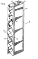
- Figure 5 is a plan view showing a three-way box connector interlockingly connecting two aligned wall panels and a third wall panel at right angles thereto.
- Figure 6 is a perspective view illustrating a corner box connector connecting two wall panels in right angular relation.
- Figure 7 is a perspective view illustrating a four-way box connector for connecting four wall panels in right angular relation.
- Figure 8 is a perspective view of a slightly modified two-way box connector having interior locking fingers for interlocking engagement with a mating insert.
- Figure 9 is a view similar to Figure 8 but showing a three-way box connector.
- Figure 10 is a perspective view of a wall panel according to the invention having a single interior web.
- Figure 11 is a perspective view of a wall panel with no interior web.
- Figure 12 is a perspective view of a box connector joiner embodying the invention.
- Figure 13 is a perspective view taken from the underside of a sloping wall cap embodying the invention.
- Figure 14 is a perspective view of the wall cap of Figure 13 taken from the top side.
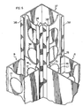
- Figure 15 is a diagrammatic view illustrating the manner in which the components of the present invention are extruded and then drilled to produce the openings through the webs thereof.
- Figure 16 is a cross-sectional view of the particular box connector shown being extruded in Figure 15.
- Figure 1 is a perspective view of a house 1 as an example of the type of building that can be erected with the thermoplastic interlocking building components of the present invention which can be assembled into walls 2 and roofing 3 with provision for doors 4 and windows 5.
- a building such as illustrated in Figure 1 is intended to be erected on a concrete pad 6 as illustrated in Figure 2 which shows how the walls 2 of the building can be anchored to the concrete pad 6 by means of anchor rods 7 when the interior of the walls 2 are filled with concrete and the like as illustrated by the arrow A.
- Suitable means such as the strip 6' may be employed to contain the concrete from spilling out from underneath the wall 2.
- the walls 2 are formed from wall panels 8 interlockingly interconnected by box connectors 9, one of which is illustrated in Figure 3.
- Each of the wall panels 8 in accordance with the invention disclosed in copending Canadian Application Serial Number 2,070,079 comprises a hollow rectilinear thermoplastic extrusion having a core 10 and coextruded outer skin 11.
- the core 10 preferably comprises a vinyl chloride and, more particularly, a polyvinyl chloride containing a suitable reinforcing and expansion controlling agent such as mineral or other fibers or other known expansion controlling agents such as a calcium carbonate.
- a suitable reinforcing and expansion controlling agent such as mineral or other fibers or other known expansion controlling agents such as a calcium carbonate.
- a reinforcing agent or constituent particularly useful for structural components of the present invention which are subject to high loading comprises small glass fibers which when anchored in a thermoplastic material such as vinyl'chloride or polyvinyl chloride provide the requisite reinforcing and expansion controlling characteristics to provide high structural strength.
- a suitable material incorporating small glass fibers which can be used in the production of these panels 8 is available under the trade-mark FIBERLOC from the B. F. Goodrich Company of Akron, Ohio, such material being described in detail in B.F. Goodrich's U.S. Patent 4,536,360 wherein very fine short glass fibers are bound within a composition of yinyl chloride resin.
- glass fibers in the PVC or other thermoplastic material while providing tensile strength and expansion control to the material creates an extrusion problem and, if they are too large and too concentrated, it is not practical to extrude the material.
- such fibers should be of the order of a few microns in diameter and a few millimeters in length and in concentrations note greater than and preferably substantially less than about 35% by weight based upon the combined glass fibers and vinyl chloride resins.
- the presence of the glass fibers creates a brittleness which makes a structure produced solely from a glass fiber reinforced plastic subject to potential fracture from impact. This potential increases with increased concentration of glass fibers.
- the smooth plastic skin may be PVC, rigid PVC, semi-rigid PVC, ABS, polycarbonate with thermoplastics available from G.E. under the trade-mark GELOY and NORYL.
- This skin 11 serves a number of useful purposes. Because of the presence of the glass fibers in the core or substrate 10, the substrate is somewhat brittle and its surfaces are rough and abrasive with portions of the glass fibers projecting through the surface of the substrate rendering the substrate somewhat porous and susceptible to the ingress of moisture which can adversely affect the bond between the glass fibers and the thermoplastic material.
- thermoplastic skin covers and seals the outer exposed surfaces of the structural component against the ingress of moisture, thereby maintaining the integrity of the binding of the glass fibers to substrate plastic.
- the outer skin 11 not only covers exposed glass fibers but these exposed glass fibers become embedded in the thermoplastic material so that the external surface of the component is totally smooth.
- the glass fibers in turn in becoming embedded in the outer skin lock the skin to the substrate or core 10 so that the expansion and contraction of the outer skin is fixed to the expansion and contraction of the core which is controlled or limited by the presence of the incorporated glass fibers which have a much smaller co-efficient of expansion than the plastic.
- the skin 11 can be formulated to include agents providing impact resistance, resistance to ultraviolet radiation and the like.
- the combination of the co-extruded core or substrate 10 and smooth skin 11 thus enable the provision of wall panels having inherent structural strength and which are essentially maintenance free, impact resistant and they will be free from corrosion, rot or rusting and will be impervious to moisture, termites and other insects.
- the core 10 may be formed of a vinyl chloride containing from about 5% to about 50% calcium carbonate and preferably about 5% to 30% calcium carbonate by weight.
- a mixture of calcium chloride and glass fibers or other reinforcing agents such as mineral fibers may be used to meet the particular load specifications required for the panel.
- each of the panels 8 is provided with two transverse webs 12 which tie the opposing faces 13 of the panel together intermediate the edge walls 14 of the panel.
- the panel 8 Adjacent each of the edge walls 14, the panel 8 is provided with inwardly extending oppositely registering grooves 15 with the width of the panel being reduced outwardly of the grooves 15 to the edge walls 14 to, in effect, provide a tongue portion 16.
- This cut out material can then be collected and reused in the extrusion of the core of a subsequent extrusion.
- the openings 17 are preferably circular openings having a diameter slightly less than the spacing between the most adjacent point 18 of the grooves 15.
- the openings 17 With the openings 17 centered on the midpoint of the edge walls 14 and midway between the panel faces 13, the openings can be cut through the edge walls 14 and also through the webs 12 without interference with the grooves 15 which extend uninterrupted throughout the length of the extrusion.
- the panels 8 are shown interlocked with the box connector 9 in the form of a hollow extruded rectangle having projecting flanges 19 terminating in inturned oppositely registering locking fingers 20 adapted to slidingly interlock with the grooves 15 of the panels 8.
- the box connector 9 is extruded with a core 21 and a coextruded outer skin 22 covering the outer surfaces of the walls 23, the flanges 19 and the locking fingers 20.
- its core 21 may comprise a PVC resin and, for example, calcium carbonate, as the expansion controlling and reinforcing agent, although other agents including small glass fibers and mixtures of agents may be used.
- outer surfaces of the walls 23 of the box connector 9 covered by the outer skin 22 are precisely aligned with the outer surfaces of the panel faces 13 with the tongue portions 16 of the panels being received in the space between the inturned locking fingers 20 and the transverse walls or webs 24 of the box connector.
- the box connector is provided with a series of openings 25 through the transverse walls or webs 24.
- these openings are circular with a diameter centered on the midpoint of the transverse walls or webs 24 of the box connector and spaced along the length thereof with the diameters of the openings substantially equal to, but less than, the spacing between the inturned locking fingers 20 so that the locking fingers are not intersected during the cutting of the openings 25.
- the panel locking grooves 15 are covered in the smooth coextruded skin 11 to provide a smooth surface for smooth sliding interlocking engagement with the smooth skin coated locking fingers 20. Further, the outside faces of the tongues 16 which form the edge walls 14 of the panels are coated with the smooth skin 11 and preferably these faces'are slightly concaved to eliminate any interference with the box connector transverse webs or walls 24.
- the material cut out from the box connector walls or webs 24 can be collected and returned to be used as material for extruding subsequent box connectors.
- the provisions of the openings 17 and 25 limits thermal transfer between the outer or exposed faces 13 of the panels 8 and the outer exposed walls 23 of the box connector 9. As a result the components provide increased insulation between the exterior and interior wall of a building such as shown in Figure 1.
- Figure 4 illustrates an arrangement of roofing panels 26 which are shown interlocked together by four-way box connectors 27 rather than a two-way box connector 9 as illustrated in Figure 3 and which would be used to provide the smooth roof formation shown in Figure 1.
- the four-way box connectors 27 provide for interlocking roof cladding to the upper surface of the roof and for engaging or supporting other structures beneath the roof.
- the roof panels 26 are similar to the wall panels 8 and it will be understood that they are extruded to provide a core and a coextruded outer skin covering the outer surfaces thereof (the separate layers not being shown).
- the reinforcing agent or agents selected for the core of the roof panels 26 will be appropriately selected.
- the reinforcing agent preferably would include at least some of the fine small diameter short glass fibers.
- the roof panels 26 are formed at opposite longitudinal edges with oppositely registering inwardly extending locking grooves 28 and edge tongues 29 for sliding interlocking engagement with the inturned locking fingers 30 carried by the flange extensions 31 of the box connectors 27. Similar inturned locking fingers 30 are provided on the box connectors 27 to project above and below the interlocked roof panels.
- the roof panels 26 have circular holes 32 cut through their edge tongues 29 and webs 33 corresponding to the circular holes or openings 17 cut out from the wall panels 8.
- the four-way box connectors 27 have circular openings 34 cut therefrom corresponding to the openings 25 in the two-way box connector.
- the provision of the openings in the roof panels and their connecting box connectors restrict thermal transfer from the upper roof surface to the underside of the roof thereby adding to the thermal insulation provided by the components. It will also be appreciated that, if desired, the roof panels and connectors can be filled with suitable insulating material.
- the webs 33 provide the requisite resistance to roof panel bending to sustain high roof panel loading augmented by the interengaging panel tongues 29 and box connector flanges 31 and locking finger 30.
- Figure 5 is a plan view illustrating the connection of three wall panels 8 into a T-formation using a three-way box connector 35.
- the three-way box connector is provided with openings 25 in three of the walls thereof so that when material is introduced as indicated by the arrow 36 into the box connector 35, which material may be concrete, sand or insulation material, it can flow through the various openings into the wall panels.
- the leg of the T-formation is closed by an end cap C formed to interlock with the tongue 16 and grooves 15 of one of the panels 8 to contain all material within the external walls of the panel and box connector.
- Figure 6 illustrates a corner box connector 37 connecting two wall panels 8 together in right angular relation.
- Box connector 37 as before, is extruded with an appropriate core and a co-extruded outer skin and is provided with the requisite inturned locking fingers 38 on adjacent sides and with the cut out circular openings 39 centered between these inturned locking fingers and having diameters less than the spacing between the locking fingers.
- Figure 7 shows a four-way locking connector 40 for interlockingly connecting four wall panels 8 in right angular relation.
- the connector 40 has inturned locking fingers 41 at all four sides of the connector and circular openings cut out therefrom in all four walls of the connector.
- the connector 40 is formed of a reinforced core with the exposed surfaces, that is the locking fingers 41 and their supporting flanges 42 coated with a smooth skin:
- the arrangement of the openings cut out from the various extruded components is such that the openings are internal of the exterior walls of the structure being assembled therefrom when they are slidingly interlocked with the appropriate mating components.
- Figure 10 is a perspective view illustrating a wall panel 8' corresponding to the panel 8 except that it has a shorter span with a single web 12'. Otherwise the panel is identical with panel 8 and like numbers refer to like parts.
- Figure 11 illustrates a still smaller wall panel 80 which may be used at a wall corner.
- Panel 80 has no internal webs but otherwise has the same interlocking features and the same cutout openings as wall panel 8 and like numbers represent like parts.
- Figure 8 illustrates a two-way box connector 9' corresponding to box connector 9 but additionally having internal key ways comprising out turned locking fingers 43 for sliding interlocking engagement with mating inserts (not shown).
- Figure 9 is a perspective view of a three-way box connector 35' similar to box connector 35 but having an internal slideway comprised by out turned locking fingers 44 for supporting an internal insert (not shown).
- Figures 13 and 14 illustrate a wall cap 45 adapted to fit down over the top of a wall formed from wall panels such as panels 8 and box connectors such as box connectors 9 to present a sloping support surface 46 for supporting a sloping roof such as illustrated at 3 in Figure 1.
- Wall cap 45 is a hollow extrusion having a bottom wall 47 adapted to rest on the upper ends of an erected wall and having downturned flanges 48 forming interconnecting means adapted to embrace opposite faces 13 of the wall.
- Webs 49 and 50 extending upwardly from the bottom wall 47 support the sloping upper surface 46 with the web 50 being of a greater height than the web 49.
- the wall cap 45 is provided at the lower side of the sloping. wall 46 with a chamber 51 which has an access slot 52 which may be closed by screening of the like (not shown). At the opposite side, the wall cap is provided with a closed chamber 53 and an open chamber 54.
- the bottom wall 47 and the sloping wall 46 are provided with circular openings 55 cut therethrough.
- the diameter of the openings while less than the spacing between the flanges 48, is greater than the spacing between the webs 49 and 50 so that during the cutting of the openings 55 a portion of the webs 49 and 50 are removed to provide access openings 56 and 57 to the chambers 51 and 54.
- bottom wall 47 and the sloping upper wall 46 will not be exposed when the wall cap 45 is installed in place, these surfaces need not be coated with a covering skin.
- the other exposed surfaces will have a skin coextruded over the core material to provide the desired smooth finish.
- Figure 12 is an extrusion for connecting box connectors together and, when in place, will be totally enclosed and will have no exposed surfaces that require coating.
- this box connector connector 58 comprises a web 59 spacing two outwardly facing channels presenting two inwardly projecting grooves 60 of a width to receive the interlocking fingers such as the fingers 20 of two adjoining box connectors 9 when their locking fingers are in abutting relation. In this manner connector 58 will lock the box connector together while being totally contained within the abutting box connector flanges and abutting interlocking fingers.
- the web 59 is provided with a plurality of circular openings 61 cut therefrom with the diameter of the openings being substantially equal to but slightly less than the spacing between the two channels 60.
- Connector 58 is preferably extruded from a polyvinyl chloride but since it is not subjected to significant loading the amount of reinforcing agent, if any, can be minimal. Again, because it is enclosed when in position, no exposed surfaces requiring a skin coating are presented.
- Figure 15 is a diagrammatic illustration of the method of manufacturing the extruded components of the present invention and illustrating the extrusion of a straight box connector 9 having a core 21 and a coextruded outer skin 22 and provided with circular openings 25 cut therefrom.
- thermoplastic material 62 formulated with the desired ingredients to form the core of the box connector 9 is fed from hopper 63 into a suitable extrusion die (not shown) from which it is delivered in a continuous stream having the requisite cross-sectional shape.
- material 64 suitable for the coextruded skin is delivered from hopper 65 and coextruded to cover the exposed surfaces of the box connector.
- the movement of the carriage 67 is such that it moves away from the extrusion apparatus at the same speed as the box connector extrusion is delivered out of the extruder so that during the drilling the extrusion and the drills have no relative movement in the direction of extrusion feed. As soon as the holes are cut and the drills retracted, they are rapidly returned rearwardly of extrusion feed to the start position to then recommence a fresh cycle of drilling while moving at the same speed as the extrusion feed.
- the drills are arranged so that when they retract they withdraw the material cut from the extrusion where it can be dropped unto a collector pan 69 and delivered back by a suitable feed 70 into the core material hopper 63.
- box connector extrusion can be cut off at the requisite lengths depending on the nature of the building structure with which it is to be employed.
Applications Claiming Priority (3)
| Application Number | Priority Date | Filing Date | Title |
|---|---|---|---|
| CA2097226 | 1993-05-28 | ||
| CA002097226A CA2097226C (fr) | 1993-05-28 | 1993-05-28 | Composants structurels thermoplastiques et structures constituees de ceux-ci |
| EP94915496A EP0702742B1 (fr) | 1993-05-28 | 1994-05-25 | Elements structuraux thermoplastiques et structures les integrant |
Related Parent Applications (2)
| Application Number | Title | Priority Date | Filing Date |
|---|---|---|---|
| EP94915496A Division EP0702742B1 (fr) | 1993-05-28 | 1994-05-25 | Elements structuraux thermoplastiques et structures les integrant |
| EP94915496.7 Division | 1994-12-08 |
Publications (3)
| Publication Number | Publication Date |
|---|---|
| EP0795654A2 true EP0795654A2 (fr) | 1997-09-17 |
| EP0795654A3 EP0795654A3 (fr) | 1997-10-29 |
| EP0795654B1 EP0795654B1 (fr) | 2002-12-04 |
Family
ID=4151706
Family Applications (2)
| Application Number | Title | Priority Date | Filing Date |
|---|---|---|---|
| EP97201538A Expired - Lifetime EP0795654B1 (fr) | 1993-05-28 | 1994-05-25 | Eléments structuraux thermoplastiques et structures les intégrant |
| EP94915496A Expired - Lifetime EP0702742B1 (fr) | 1993-05-28 | 1994-05-25 | Elements structuraux thermoplastiques et structures les integrant |
Family Applications After (1)
| Application Number | Title | Priority Date | Filing Date |
|---|---|---|---|
| EP94915496A Expired - Lifetime EP0702742B1 (fr) | 1993-05-28 | 1994-05-25 | Elements structuraux thermoplastiques et structures les integrant |
Country Status (34)
| Country | Link |
|---|---|
| US (1) | US5729944A (fr) |
| EP (2) | EP0795654B1 (fr) |
| JP (1) | JP3627053B2 (fr) |
| KR (1) | KR100311301B1 (fr) |
| CN (1) | CN1082120C (fr) |
| AT (2) | ATE164651T1 (fr) |
| AU (1) | AU680251B2 (fr) |
| BG (1) | BG61952B1 (fr) |
| BR (1) | BR9406665A (fr) |
| CA (2) | CA2232203A1 (fr) |
| CO (1) | CO4370787A1 (fr) |
| CZ (1) | CZ314795A3 (fr) |
| DE (2) | DE69409378T2 (fr) |
| DK (1) | DK0702742T3 (fr) |
| EC (1) | ECSP941061A (fr) |
| EG (1) | EG20398A (fr) |
| ES (2) | ES2115234T3 (fr) |
| FI (1) | FI109139B (fr) |
| HK (1) | HK1006351A1 (fr) |
| HU (1) | HU214467B (fr) |
| IN (1) | IN189198B (fr) |
| MX (1) | MXPA94003998A (fr) |
| NO (1) | NO954802L (fr) |
| NZ (1) | NZ266120A (fr) |
| OA (1) | OA10246A (fr) |
| PL (1) | PL185131B1 (fr) |
| PT (1) | PT795654E (fr) |
| RO (1) | RO117930B1 (fr) |
| RU (1) | RU2126074C1 (fr) |
| SG (1) | SG48835A1 (fr) |
| SK (1) | SK146595A3 (fr) |
| UA (1) | UA46708C2 (fr) |
| WO (1) | WO1994028262A2 (fr) |
| ZA (1) | ZA943697B (fr) |
Cited By (3)
| Publication number | Priority date | Publication date | Assignee | Title |
|---|---|---|---|---|
| WO1999001623A2 (fr) * | 1997-07-03 | 1999-01-14 | Brighton, Barry, David | Unites de construction a accouplement reciproque |
| WO2000031356A1 (fr) * | 1998-11-26 | 2000-06-02 | Mitie Plastics Limited | Structures porteuses de charge |
| CN100371548C (zh) * | 2004-04-12 | 2008-02-27 | 杨达华 | 一种板状活动型材的连接件 |
Families Citing this family (94)
| Publication number | Priority date | Publication date | Assignee | Title |
|---|---|---|---|---|
| US6389010B1 (en) * | 1995-10-05 | 2002-05-14 | Intermec Ip Corp. | Hierarchical data collection network supporting packetized voice communications among wireless terminals and telephones |
| CA2124492C (fr) * | 1994-05-27 | 2005-12-06 | Vittorio De Zen | Systeme de construction a profiles creux perfores |
| CA2134959C (fr) * | 1994-11-02 | 2002-06-11 | Vittorio De Zen | Elements de construction modulaire a cote de resistance au feu |
| CA2170680A1 (fr) * | 1996-02-29 | 1997-08-30 | Vittorio De Zen | Methode d'assemblage de murs de beton coule |
| CA2170681A1 (fr) * | 1996-02-29 | 1997-08-30 | Vittorio De Zen | Mur isole; les elements pour sa construction |
| US6079175A (en) * | 1997-04-09 | 2000-06-27 | Clear; Theodore E. | Cementitious structural building panel |
| US6167669B1 (en) | 1997-11-03 | 2001-01-02 | Louis Joseph Lanc | Concrete plastic unit CPU |
| US6032424A (en) * | 1998-03-23 | 2000-03-07 | Dial, Jr.; Ted C. | Block system |
| US6105315A (en) * | 1998-07-24 | 2000-08-22 | Stoecklein; Walter J. | Modular mausoleum and crypt structure and methods of constructing same |
| EP1081305A4 (fr) * | 1999-03-19 | 2005-03-16 | Toray Industries | Materiau de plastique arme pour toitures, son procede de fabrication, et structures et procedes de liaison d'elements dudit materiau |
| ATE323199T1 (de) | 1999-04-23 | 2006-04-15 | Dow Global Technologies Inc | Isolierende wandstruktur |
| US7243464B1 (en) * | 1999-05-10 | 2007-07-17 | Crowell James H | Modular building system |
| US7251919B2 (en) * | 1999-11-02 | 2007-08-07 | Ray Manuel A | Lightweight building component |
| US6668512B2 (en) | 1999-11-02 | 2003-12-30 | Ray T. Forms, Inc. | Lightweight building component |
| US7444788B2 (en) * | 2002-03-15 | 2008-11-04 | Cecil Morin | Extruded permanent form-work for concrete |
| US8720133B1 (en) * | 2000-02-18 | 2014-05-13 | Christopher M. Hunt | Autoclaved aerated concrete structure components |
| US6804925B1 (en) | 2001-02-08 | 2004-10-19 | Daedalus Project, Inc. | Composite building material and panels made therefrom |
| US6705057B2 (en) | 2001-03-06 | 2004-03-16 | Smyer, Iii Sidney W. | Modular block system and method of construction |
| AUPR824001A0 (en) * | 2001-10-12 | 2001-11-08 | Dincel, Burak | A building element |
| AUPR875601A0 (en) * | 2001-11-03 | 2001-11-29 | Hills, Danny | Building component |
| CA2372358C (fr) * | 2002-02-20 | 2006-05-09 | Aluma Enterprises Inc. | Systeme de fermes suspendues sur colonnes |
| IL148400A (en) * | 2002-02-26 | 2007-06-17 | Dynamic Shells Ltd | Modular construction and method for its construction |
| CA2449145A1 (fr) | 2002-11-12 | 2004-05-12 | Kafko International Inc. | Structure murale a courbure ajustable a l'interieur de laquelle on peut couler du beton |
| US7856773B2 (en) * | 2003-07-24 | 2010-12-28 | Wagdy Agaiby | All-in-one modular construction system |
| US20050056822A1 (en) * | 2003-09-12 | 2005-03-17 | Linford Paul M. | Apparatus and method for reinforcing a vinyl beam |
| US7028440B2 (en) * | 2003-09-29 | 2006-04-18 | Dale Brisson | Modular homes |
| US20080245013A1 (en) * | 2003-10-30 | 2008-10-09 | Geoffrey Carlisle | Building Formwork Module for Use in a Modular Concrete Formwork System |
| US20070228216A1 (en) * | 2006-04-03 | 2007-10-04 | Be Aerospace, Inc. | Galley assembly for an aircraft |
| US20090165401A1 (en) * | 2006-10-04 | 2009-07-02 | Smalley Iii Arthur L | Method and system for a modular building structure |
| KR101242267B1 (ko) * | 2006-12-06 | 2013-03-12 | (주)엘지하우시스 | 복합재료를 사용하는 건축구조용 부재 |
| KR100848566B1 (ko) | 2007-01-17 | 2008-07-25 | 주식회사 준별에프알피산업 | 복합 구조재 밸브실 및 그 시공방법 |
| CA2681963C (fr) | 2007-04-02 | 2012-08-07 | Cfs Concrete Forming Systems Inc. | Procedes et appareil permettant de creer des revetements destines a des structures en beton |
| AU2007263407C1 (en) * | 2007-09-11 | 2017-08-17 | Klionic Industries Pty Ltd | Building structures and components therefor |
| AU2008324734B2 (en) * | 2007-11-09 | 2015-05-07 | Cfs Concrete Forming Systems Inc. | Pivotally activated connector components for form-work systems and methods for use of same |
| CA2712533C (fr) | 2008-01-21 | 2016-06-21 | Octaform Systems Inc. | Systemes de coffrage fixe pour fenetres et autres ouvertures de batiment |
| US8333045B2 (en) * | 2008-03-06 | 2012-12-18 | Bruce Lung | Architectural structure |
| US20090313937A1 (en) * | 2008-05-05 | 2009-12-24 | Stainless Structurals, Llc | Steel beams and related assemblies and methods |
| WO2009137489A2 (fr) * | 2008-05-05 | 2009-11-12 | Stainless Structurals, Llc | Poutres en acier et procédés associés |
| US9097000B2 (en) * | 2008-10-03 | 2015-08-04 | Thomas M. Espinosa | Hold down system using hollow bearing members |
| US8943774B2 (en) | 2009-04-27 | 2015-02-03 | Cfs Concrete Forming Systems Inc. | Methods and apparatus for restoring, repairing, reinforcing and/or protecting structures using concrete |
| EP3156562B1 (fr) | 2009-01-07 | 2019-08-14 | CFS Concrete Forming Systems Inc. | Procédé et appareil pour restaurer, réparer, renforcer et/ou protéger des structures utilisant du béton |
| CA2888405C (fr) | 2009-02-18 | 2017-03-21 | Cfs Concrete Forming Systems Inc. | Systeme de raccordement par emboitement pour coffrage perdu |
| CA2654992C (fr) * | 2009-02-20 | 2011-08-23 | Nuform Building Technologies Inc. | Construction de structures murales et de leurs elements |
| US20100243369A1 (en) * | 2009-03-31 | 2010-09-30 | Nuform Building Technologies Inc. | Highway noise barrier |
| BRMU8901471Y1 (pt) | 2009-07-08 | 2018-01-30 | Hinz Helmuth | Aperfeiçoamentos introduzidos no sistema construtivo integrado de perfis para paredes verticais modulares de pvc extrudados |
| US8202596B2 (en) * | 2009-12-31 | 2012-06-19 | Building Materials Investment Corporation | Standing seam profile for thermoplastic roof ornamentation |
| US8313597B2 (en) * | 2009-12-31 | 2012-11-20 | Building Materials Investment Corporation | Methods for attaching thermoplastic profile to roofing membrane and dual welding device |
| US8973313B2 (en) * | 2010-03-04 | 2015-03-10 | Michael Bettiol | Building envelope member with internal water reservoir |
| WO2012003587A1 (fr) | 2010-07-06 | 2012-01-12 | Cfs Concrete Forming Systems Inc. | Système de poussée pour restaurer, réparer, renforcer, protéger, isoler et/ou revêtir des structures |
| US10822790B2 (en) * | 2010-08-24 | 2020-11-03 | Innovative Structural Building Products, Llc | Frameless construction using single and double plenum panels |
| DE102011002843A1 (de) * | 2011-01-18 | 2012-07-19 | Ekotop Oy | Verbindungsstück für holzbasierte Wandstruktur, holzbasierte Wandstruktur, und Gebäude |
| MX337607B (es) * | 2011-04-11 | 2016-03-10 | Burak Dincel | Un elemento de construcción para un panel de construcción estructural. |
| ES2398821B2 (es) * | 2011-07-12 | 2014-02-06 | Entreriver, S.A. | Procedimiento industrializado de construcción de edificaciones y conjuntos prefabricados de uso en dicho procedimiento |
| US20140166665A1 (en) * | 2011-07-14 | 2014-06-19 | Bernard McNamara | Method of assembly of modular reservoir with integral compressible sealing strips and expansion joint |
| FI126050B (sv) * | 2011-10-17 | 2016-06-15 | Uponor Infra Oy | Tredimensionella konstruktioner |
| WO2013075251A1 (fr) | 2011-11-24 | 2013-05-30 | Cfs Concrete Forming Systems Inc. | Coffrage restant en place avec liaisons de prise et de butée |
| CA2855739C (fr) | 2011-11-24 | 2016-10-11 | Cfs Concrete Forming Systems Inc. | Coffrage restant en place avec panneaux anti-deformation |
| CA2988025C (fr) | 2012-01-05 | 2018-08-14 | Cfs Concrete Forming Systems Inc. | Systemes pour restaurer, reparer, renforcer, proteger, isoler et gainer des structures avec des composants en porte-a-faux localisables |
| US10151119B2 (en) | 2012-01-05 | 2018-12-11 | Cfs Concrete Forming Systems Inc. | Tool for making panel-to-panel connections for stay-in-place liners used to repair structures and methods for using same |
| WO2013102274A1 (fr) | 2012-01-05 | 2013-07-11 | Cfs Concrete Forming Systems Inc. | Connexions panneau à panneau pour garnitures de maintien en place utilisées pour réparer des structures |
| US9850658B2 (en) * | 2012-09-17 | 2017-12-26 | Eleven Solutions Rfe S.A. De C.V. | Modular, multiperforated permanent formwork construction system for reinforced concrete |
| CN105051296B (zh) | 2012-11-30 | 2017-07-11 | 叶列文解决方案股份公司 | 具有绿植墙的建筑物所用的生态建筑系统 |
| KR101422076B1 (ko) * | 2013-01-25 | 2014-07-28 | 강종우 | 플랫타이 및 이 플랫타이와 비금속제 거푸집틀을 이용한 거푸집 설치방법 |
| KR101250860B1 (ko) * | 2013-02-05 | 2013-04-05 | 강종우 | 거푸집틀 및 이를 이용한 거푸집 설치방법 |
| US8677713B1 (en) | 2013-03-06 | 2014-03-25 | Epi 04, Inc. | Extruded wall panel system and method of forming |
| ITMI20130620A1 (it) * | 2013-04-16 | 2014-10-17 | Gi Plast S R L | Pannello per coperture con funzione anti-gocciolamento |
| FR3011863B1 (fr) * | 2013-10-16 | 2021-05-14 | L Destouches | Dispositif prefabrique de construction |
| CN103526934A (zh) * | 2013-10-31 | 2014-01-22 | 曾寿喜 | 一种无砖块墙体与装饰面的同步建造方法 |
| CN105940165B (zh) | 2013-12-06 | 2019-01-15 | Cfs 混凝土模板系统公司 | 结构件覆层装饰部件、制造及使用该结构件覆层装饰部件的方法 |
| US9163393B2 (en) * | 2014-03-14 | 2015-10-20 | Margie K. Carroll | Panel construction device |
| AU2015240346B2 (en) | 2014-04-04 | 2019-04-18 | Cfs Concrete Forming Systems Inc. | Liquid and gas-impermeable connections for panels of stay- in-place form-work systems |
| CN103912116A (zh) * | 2014-04-04 | 2014-07-09 | 华浚塑料建材有限公司 | 一种pvc建筑墙体连接模块 |
| AU2015278245B2 (en) * | 2014-06-16 | 2018-08-30 | Steadiform Holdings Pty Ltd | Formwork |
| CA2910515C (fr) * | 2014-10-31 | 2021-03-30 | John Martin Herrick | Ameliorations relatives aux serres |
| CA2916690A1 (fr) * | 2015-01-07 | 2016-07-07 | James Walker | Construction sans cadre employant des panneaux simples ou doubles entree-sortie |
| BR202015008514U2 (pt) * | 2015-04-15 | 2016-10-18 | Rogério Saad Noé | melhorias introduzidas no sistema construtivo de perfis modulares de pvc extrudados e co-extrdudados para composição de paredes |
| AU2016256485B2 (en) * | 2015-04-29 | 2020-07-30 | Burak Dincel | A building element |
| US9617731B2 (en) | 2015-06-04 | 2017-04-11 | U.S. Farathane Corporation | Modular wall system and kit incorporating extruded end interlocking portions in addition to base support track molding and attachable top cap |
| ITUB20154818A1 (it) * | 2015-10-22 | 2017-04-22 | Angelo Candiracci | Struttura di pannello edilizio anti-perforazione |
| EA028813B1 (ru) * | 2015-12-02 | 2018-01-31 | Александр Владимирович Ромашкин | Строительный блок из древесно-полимерного композиционного материала |
| CA3008915A1 (fr) | 2015-12-31 | 2017-07-06 | Cfs Concrete Forming Systems Inc. | Appareil de revetement de structure a largeur ajustable et outil pour celui-ci |
| MY170079A (en) * | 2017-03-06 | 2019-07-03 | Csr Building Products Ltd | Formwork system |
| RU2643875C1 (ru) * | 2017-03-16 | 2018-02-06 | Павел Андреевич Еговцев | Композитные профильные элементы с сетчатой структурой (варианты) |
| CA3056152C (fr) | 2017-04-03 | 2023-07-25 | Cfs Concrete Forming Systems Inc. | Revetements de maintien en place a grande portee |
| UY37212A (es) * | 2017-04-28 | 2018-11-30 | Rey Farias Fernando | Bloque encastrable de construcción |
| CH714202A1 (fr) * | 2017-09-29 | 2019-03-29 | Ustinov Igor | Système de construction pour un module d'un bâtiment. |
| US20190127966A1 (en) * | 2017-11-01 | 2019-05-02 | Marlon Howard Stewart | Permanent forms for composite construction columns and beams and method of building construction |
| EP3728763A4 (fr) | 2017-12-22 | 2021-10-13 | CFS Concrete Forming Systems Inc. | Douilles-entretoises à encliquetage pour restaurer, réparer, renforcer, protéger, isoler et/ou barder des structures |
| US10870978B2 (en) | 2018-03-09 | 2020-12-22 | Cetres Holdings, Llc | Reinforced stud-framed wall |
| RU2681747C1 (ru) * | 2018-05-07 | 2019-03-12 | Виктор Николаевич Молодцев | Трёхкамерный стеновой строительный профиль |
| EP3921493A4 (fr) | 2019-02-08 | 2022-11-09 | CFS Concrete Forming Systems Inc. | Dispositifs de retenue permettant de restaurer, réparer, renforcer, protéger, isoler et/ou habiller des structures |
| US20220145556A1 (en) * | 2019-02-24 | 2022-05-12 | Avraham BEN EZRI | Vertically-oriented barrier |
| US11680403B2 (en) * | 2020-09-21 | 2023-06-20 | Amp Ip Llc | Multi-purpose structural panels and systems for assembling structures |
| US11761203B2 (en) | 2021-01-12 | 2023-09-19 | Vision Profile Extrusions Limited | Mold-in-place concrete formwork |
Citations (5)
| Publication number | Priority date | Publication date | Assignee | Title |
|---|---|---|---|---|
| US1958124A (en) * | 1931-07-25 | 1934-05-08 | Bemis Ind Inc | Building construction |
| FR2007695A1 (en) * | 1968-05-02 | 1970-01-09 | Goldbach Sperr Fassholz | Perforated plate for homogenising and temp equalising |
| US4722952A (en) * | 1986-05-09 | 1988-02-02 | Elkem A/S | Resin compositions |
| GB2193465A (en) * | 1986-07-15 | 1988-02-10 | Cambrian Plastics Ltd | Improvements relating to reinforced bodies |
| EP0320745A1 (fr) * | 1987-12-11 | 1989-06-21 | The B.F. Goodrich Company | Structure modulaire de construction et éléments préfabriqués utilisés dans cette structure et méthodes de construction |
Family Cites Families (9)
| Publication number | Priority date | Publication date | Assignee | Title |
|---|---|---|---|---|
| US1960961A (en) * | 1932-04-01 | 1934-05-29 | Charles W Thomas | Metal construction section |
| US3284971A (en) * | 1959-08-11 | 1966-11-15 | Warren R Attwood | Structural elements for metal framing systems |
| US3662507A (en) * | 1970-03-11 | 1972-05-16 | Arthur J Espeland | Preformed building wall construction |
| US3950902A (en) * | 1973-09-20 | 1976-04-20 | Stout Robert K | Concrete structure including modular concrete beams |
| US3992839A (en) * | 1974-11-21 | 1976-11-23 | Ethyl Corporation | Snap-on paneling |
| US4557091A (en) * | 1982-02-10 | 1985-12-10 | Corflex International, Inc. | Extruded structural system |
| US4536360A (en) * | 1984-07-13 | 1985-08-20 | The B. F. Goodrich Company | Glass fiber reinforced vinyl chloride polymer products and process for their preparation |
| NO165605C (no) * | 1988-08-15 | 1991-03-06 | Nils Nessa | Sammenfoeybare forskalingselementer for stoeping av saerlig vegg- eller andre konstruksjoner samt fremgangsmaate til stoeping av det samme. |
| US5311718A (en) * | 1992-07-02 | 1994-05-17 | Trousilek Jan P V | Form for use in fabricating wall structures and a wall structure fabrication system employing said form |
-
1993
- 1993-05-28 CA CA002232203A patent/CA2232203A1/fr not_active Abandoned
- 1993-05-28 CA CA002097226A patent/CA2097226C/fr not_active Expired - Lifetime
- 1993-12-27 CO CO93424374A patent/CO4370787A1/es unknown
-
1994
- 1994-03-28 EC EC1994001061A patent/ECSP941061A/es unknown
- 1994-05-20 IN IN644DE1994 patent/IN189198B/en unknown
- 1994-05-25 KR KR1019950705307A patent/KR100311301B1/ko not_active IP Right Cessation
- 1994-05-25 ES ES94915496T patent/ES2115234T3/es not_active Expired - Lifetime
- 1994-05-25 BR BR9406665A patent/BR9406665A/pt not_active IP Right Cessation
- 1994-05-25 DK DK94915496.7T patent/DK0702742T3/da active
- 1994-05-25 HU HU9503272A patent/HU214467B/hu not_active IP Right Cessation
- 1994-05-25 US US08/553,415 patent/US5729944A/en not_active Expired - Lifetime
- 1994-05-25 AT AT94915496T patent/ATE164651T1/de not_active IP Right Cessation
- 1994-05-25 EP EP97201538A patent/EP0795654B1/fr not_active Expired - Lifetime
- 1994-05-25 DE DE69409378T patent/DE69409378T2/de not_active Expired - Fee Related
- 1994-05-25 SG SG1996002563A patent/SG48835A1/en unknown
- 1994-05-25 CZ CZ953147A patent/CZ314795A3/cs unknown
- 1994-05-25 AT AT97201538T patent/ATE229112T1/de not_active IP Right Cessation
- 1994-05-25 RO RO95-02052A patent/RO117930B1/ro unknown
- 1994-05-25 JP JP50004795A patent/JP3627053B2/ja not_active Expired - Fee Related
- 1994-05-25 NZ NZ266120A patent/NZ266120A/en unknown
- 1994-05-25 PT PT97201538T patent/PT795654E/pt unknown
- 1994-05-25 AU AU67191/94A patent/AU680251B2/en not_active Ceased
- 1994-05-25 WO PCT/CA1994/000274 patent/WO1994028262A2/fr not_active Application Discontinuation
- 1994-05-25 PL PL94311741A patent/PL185131B1/pl not_active IP Right Cessation
- 1994-05-25 SK SK1465-95A patent/SK146595A3/sk unknown
- 1994-05-25 DE DE69431849T patent/DE69431849T2/de not_active Expired - Fee Related
- 1994-05-25 UA UA95115028A patent/UA46708C2/uk unknown
- 1994-05-25 EP EP94915496A patent/EP0702742B1/fr not_active Expired - Lifetime
- 1994-05-25 RU RU95122586A patent/RU2126074C1/ru not_active IP Right Cessation
- 1994-05-25 ES ES97201538T patent/ES2185862T3/es not_active Expired - Lifetime
- 1994-05-25 CN CN94192809A patent/CN1082120C/zh not_active Expired - Fee Related
- 1994-05-26 ZA ZA943697A patent/ZA943697B/xx unknown
- 1994-05-27 MX MXPA94003998A patent/MXPA94003998A/es unknown
- 1994-05-28 EG EG30594A patent/EG20398A/xx active
-
1995
- 1995-11-15 FI FI955513A patent/FI109139B/fi active
- 1995-11-24 BG BG100167A patent/BG61952B1/bg unknown
- 1995-11-27 NO NO954802A patent/NO954802L/no not_active Application Discontinuation
- 1995-11-28 OA OA60748A patent/OA10246A/en unknown
-
1998
- 1998-06-17 HK HK98105462A patent/HK1006351A1/xx not_active IP Right Cessation
Patent Citations (5)
| Publication number | Priority date | Publication date | Assignee | Title |
|---|---|---|---|---|
| US1958124A (en) * | 1931-07-25 | 1934-05-08 | Bemis Ind Inc | Building construction |
| FR2007695A1 (en) * | 1968-05-02 | 1970-01-09 | Goldbach Sperr Fassholz | Perforated plate for homogenising and temp equalising |
| US4722952A (en) * | 1986-05-09 | 1988-02-02 | Elkem A/S | Resin compositions |
| GB2193465A (en) * | 1986-07-15 | 1988-02-10 | Cambrian Plastics Ltd | Improvements relating to reinforced bodies |
| EP0320745A1 (fr) * | 1987-12-11 | 1989-06-21 | The B.F. Goodrich Company | Structure modulaire de construction et éléments préfabriqués utilisés dans cette structure et méthodes de construction |
Cited By (5)
| Publication number | Priority date | Publication date | Assignee | Title |
|---|---|---|---|---|
| WO1999001623A2 (fr) * | 1997-07-03 | 1999-01-14 | Brighton, Barry, David | Unites de construction a accouplement reciproque |
| WO1999001623A3 (fr) * | 1997-07-03 | 1999-03-18 | Brighton Barry David | Unites de construction a accouplement reciproque |
| WO2000031356A1 (fr) * | 1998-11-26 | 2000-06-02 | Mitie Plastics Limited | Structures porteuses de charge |
| AU747714B2 (en) * | 1998-11-26 | 2002-05-23 | Ischebeck Titan Ltd. | Load-bearing structures |
| CN100371548C (zh) * | 2004-04-12 | 2008-02-27 | 杨达华 | 一种板状活动型材的连接件 |
Also Published As
Similar Documents
| Publication | Publication Date | Title |
|---|---|---|
| EP0702742B1 (fr) | Elements structuraux thermoplastiques et structures les integrant | |
| US6189269B1 (en) | Thermoplastic wall forming member with wiring channel | |
| AU671323B2 (en) | Thermoplastic structural system and components therefor and method of making same | |
| CA2124492C (fr) | Systeme de construction a profiles creux perfores | |
| US5953880A (en) | Fire rated modular building system | |
| DE60027287T2 (de) | Isolierende wandstruktur | |
| DE2836862A1 (de) | Vorfertigungssystem fuer gebaeudewaende | |
| AU709600B2 (en) | Thermoplastic structural components and structures formed therefrom | |
| CA2206723C (fr) | Element de mur en materiau thermoplastique avec chemin de cable | |
| CN1100685A (zh) | 热塑结构系统和其所用的构件以及它们的制造方法 | |
| CN1225968A (zh) | 用于结构建筑系统的空心线性热缩结构构件 |
Legal Events
| Date | Code | Title | Description |
|---|---|---|---|
| PUAI | Public reference made under article 153(3) epc to a published international application that has entered the european phase |
Free format text: ORIGINAL CODE: 0009012 |
|
| PUAL | Search report despatched |
Free format text: ORIGINAL CODE: 0009013 |
|
| 17P | Request for examination filed |
Effective date: 19970606 |
|
| AC | Divisional application: reference to earlier application |
Ref document number: 702742 Country of ref document: EP |
|
| AK | Designated contracting states |
Kind code of ref document: A2 Designated state(s): AT BE CH DE DK ES FR GB GR IE IT LI LU MC NL PT SE |
|
| AK | Designated contracting states |
Kind code of ref document: A3 Designated state(s): AT BE CH DE DK ES FR GB GR IE IT LI LU MC NL PT SE |
|
| 17Q | First examination report despatched |
Effective date: 19990401 |
|
| GRAG | Despatch of communication of intention to grant |
Free format text: ORIGINAL CODE: EPIDOS AGRA |
|
| GRAG | Despatch of communication of intention to grant |
Free format text: ORIGINAL CODE: EPIDOS AGRA |
|
| GRAH | Despatch of communication of intention to grant a patent |
Free format text: ORIGINAL CODE: EPIDOS IGRA |
|
| GRAH | Despatch of communication of intention to grant a patent |
Free format text: ORIGINAL CODE: EPIDOS IGRA |
|
| GRAA | (expected) grant |
Free format text: ORIGINAL CODE: 0009210 |
|
| AC | Divisional application: reference to earlier application |
Ref document number: 702742 Country of ref document: EP |
|
| AK | Designated contracting states |
Kind code of ref document: B1 Designated state(s): AT BE CH DE DK ES FR GB GR IE IT LI LU MC NL PT SE |
|
| PG25 | Lapsed in a contracting state [announced via postgrant information from national office to epo] |
Ref country code: GR Free format text: LAPSE BECAUSE OF FAILURE TO SUBMIT A TRANSLATION OF THE DESCRIPTION OR TO PAY THE FEE WITHIN THE PRESCRIBED TIME-LIMIT Effective date: 20021204 Ref country code: AT Free format text: LAPSE BECAUSE OF FAILURE TO SUBMIT A TRANSLATION OF THE DESCRIPTION OR TO PAY THE FEE WITHIN THE PRESCRIBED TIME-LIMIT Effective date: 20021204 |
|
| REF | Corresponds to: |
Ref document number: 229112 Country of ref document: AT Date of ref document: 20021215 Kind code of ref document: T |
|
| REG | Reference to a national code |
Ref country code: GB Ref legal event code: FG4D |
|
| REG | Reference to a national code |
Ref country code: CH Ref legal event code: EP |
|
| RAP2 | Party data changed (patent owner data changed or rights of a patent transferred) |
Owner name: ROYAL BUILDING SYSTEMS (CDN) LIMITED |
|
| REG | Reference to a national code |
Ref country code: IE Ref legal event code: FG4D |
|
| REF | Corresponds to: |
Ref document number: 69431849 Country of ref document: DE Date of ref document: 20030116 |
|
| NLT2 | Nl: modifications (of names), taken from the european patent patent bulletin |
Owner name: ROYAL BUILDING SYSTEMS (CDN) LIMITED |
|
| PG25 | Lapsed in a contracting state [announced via postgrant information from national office to epo] |
Ref country code: DK Free format text: LAPSE BECAUSE OF FAILURE TO SUBMIT A TRANSLATION OF THE DESCRIPTION OR TO PAY THE FEE WITHIN THE PRESCRIBED TIME-LIMIT Effective date: 20030304 |
|
| REG | Reference to a national code |
Ref country code: CH Ref legal event code: NV Representative=s name: SCHMAUDER & PARTNER AG PATENTANWALTSBUERO |
|
| REG | Reference to a national code |
Ref country code: PT Ref legal event code: SC4A Free format text: AVAILABILITY OF NATIONAL TRANSLATION Effective date: 20030221 |
|
| REG | Reference to a national code |
Ref country code: ES Ref legal event code: FG2A Ref document number: 2185862 Country of ref document: ES Kind code of ref document: T3 |
|
| PG25 | Lapsed in a contracting state [announced via postgrant information from national office to epo] |
Ref country code: LU Free format text: LAPSE BECAUSE OF NON-PAYMENT OF DUE FEES Effective date: 20030525 Ref country code: GB Free format text: LAPSE BECAUSE OF NON-PAYMENT OF DUE FEES Effective date: 20030525 |
|
| PG25 | Lapsed in a contracting state [announced via postgrant information from national office to epo] |
Ref country code: SE Free format text: LAPSE BECAUSE OF NON-PAYMENT OF DUE FEES Effective date: 20030526 Ref country code: IE Free format text: LAPSE BECAUSE OF NON-PAYMENT OF DUE FEES Effective date: 20030526 Ref country code: ES Free format text: LAPSE BECAUSE OF NON-PAYMENT OF DUE FEES Effective date: 20030526 |
|
| PG25 | Lapsed in a contracting state [announced via postgrant information from national office to epo] |
Ref country code: MC Free format text: LAPSE BECAUSE OF NON-PAYMENT OF DUE FEES Effective date: 20030531 Ref country code: LI Free format text: LAPSE BECAUSE OF NON-PAYMENT OF DUE FEES Effective date: 20030531 Ref country code: CH Free format text: LAPSE BECAUSE OF NON-PAYMENT OF DUE FEES Effective date: 20030531 Ref country code: BE Free format text: LAPSE BECAUSE OF NON-PAYMENT OF DUE FEES Effective date: 20030531 |
|
| ET | Fr: translation filed | ||
| PLBE | No opposition filed within time limit |
Free format text: ORIGINAL CODE: 0009261 |
|
| STAA | Information on the status of an ep patent application or granted ep patent |
Free format text: STATUS: NO OPPOSITION FILED WITHIN TIME LIMIT |
|
| 26N | No opposition filed |
Effective date: 20030905 |
|
| BERE | Be: lapsed |
Owner name: *ROYAL BUILDING SYSTEMS (CDN) LTD Effective date: 20030531 |
|
| PG25 | Lapsed in a contracting state [announced via postgrant information from national office to epo] |
Ref country code: NL Free format text: LAPSE BECAUSE OF NON-PAYMENT OF DUE FEES Effective date: 20031201 |
|
| PG25 | Lapsed in a contracting state [announced via postgrant information from national office to epo] |
Ref country code: DE Free format text: LAPSE BECAUSE OF NON-PAYMENT OF DUE FEES Effective date: 20031202 |
|
| EUG | Se: european patent has lapsed | ||
| GBPC | Gb: european patent ceased through non-payment of renewal fee |
Effective date: 20030525 |
|
| REG | Reference to a national code |
Ref country code: CH Ref legal event code: PL |
|
| PG25 | Lapsed in a contracting state [announced via postgrant information from national office to epo] |
Ref country code: FR Free format text: LAPSE BECAUSE OF NON-PAYMENT OF DUE FEES Effective date: 20040130 |
|
| NLV4 | Nl: lapsed or anulled due to non-payment of the annual fee |
Effective date: 20031201 |
|
| REG | Reference to a national code |
Ref country code: FR Ref legal event code: ST |
|
| REG | Reference to a national code |
Ref country code: IE Ref legal event code: MM4A |
|
| REG | Reference to a national code |
Ref country code: ES Ref legal event code: FD2A Effective date: 20030526 |
|
| PG25 | Lapsed in a contracting state [announced via postgrant information from national office to epo] |
Ref country code: PT Free format text: LAPSE BECAUSE OF NON-PAYMENT OF DUE FEES Effective date: 20041015 |
|
| PG25 | Lapsed in a contracting state [announced via postgrant information from national office to epo] |
Ref country code: IT Free format text: LAPSE BECAUSE OF NON-PAYMENT OF DUE FEES;WARNING: LAPSES OF ITALIAN PATENTS WITH EFFECTIVE DATE BEFORE 2007 MAY HAVE OCCURRED AT ANY TIME BEFORE 2007. THE CORRECT EFFECTIVE DATE MAY BE DIFFERENT FROM THE ONE RECORDED. Effective date: 20050525 |
|
| PG25 | Lapsed in a contracting state [announced via postgrant information from national office to epo] |
Ref country code: PT Free format text: LAPSE BECAUSE OF NON-PAYMENT OF DUE FEES Effective date: 20030525 |