EP0794831B1 - Mischgerät - Google Patents
Mischgerät Download PDFInfo
- Publication number
- EP0794831B1 EP0794831B1 EP95941649A EP95941649A EP0794831B1 EP 0794831 B1 EP0794831 B1 EP 0794831B1 EP 95941649 A EP95941649 A EP 95941649A EP 95941649 A EP95941649 A EP 95941649A EP 0794831 B1 EP0794831 B1 EP 0794831B1
- Authority
- EP
- European Patent Office
- Prior art keywords
- housing
- mixing
- mass
- container
- carrier
- Prior art date
- Legal status (The legal status is an assumption and is not a legal conclusion. Google has not performed a legal analysis and makes no representation as to the accuracy of the status listed.)
- Expired - Lifetime
Links
- 230000005484 gravity Effects 0.000 claims abstract description 20
- 238000006073 displacement reaction Methods 0.000 claims description 6
- 230000005540 biological transmission Effects 0.000 claims description 5
- 230000009969 flowable effect Effects 0.000 description 11
- 239000007788 liquid Substances 0.000 description 1
- 230000002093 peripheral effect Effects 0.000 description 1
- 239000000725 suspension Substances 0.000 description 1
- 238000009827 uniform distribution Methods 0.000 description 1
Images


Classifications
-
- B—PERFORMING OPERATIONS; TRANSPORTING
- B01—PHYSICAL OR CHEMICAL PROCESSES OR APPARATUS IN GENERAL
- B01F—MIXING, e.g. DISSOLVING, EMULSIFYING OR DISPERSING
- B01F29/00—Mixers with rotating receptacles
- B01F29/10—Mixers with rotating receptacles with receptacles rotated about two different axes, e.g. receptacles having planetary motion
-
- B—PERFORMING OPERATIONS; TRANSPORTING
- B01—PHYSICAL OR CHEMICAL PROCESSES OR APPARATUS IN GENERAL
- B01F—MIXING, e.g. DISSOLVING, EMULSIFYING OR DISPERSING
- B01F29/00—Mixers with rotating receptacles
- B01F29/40—Parts or components, e.g. receptacles, feeding or discharging means
- B01F29/403—Disposition of the rotor axis
- B01F29/4035—Disposition of the rotor axis with a receptacle rotating around two or more axes
- B01F29/40354—Disposition of the rotor axis with a receptacle rotating around two or more axes arranged for planetary motion
-
- B—PERFORMING OPERATIONS; TRANSPORTING
- B01—PHYSICAL OR CHEMICAL PROCESSES OR APPARATUS IN GENERAL
- B01F—MIXING, e.g. DISSOLVING, EMULSIFYING OR DISPERSING
- B01F35/00—Accessories for mixers; Auxiliary operations or auxiliary devices; Parts or details of general application
- B01F35/40—Mounting or supporting mixing devices or receptacles; Clamping or holding arrangements therefor
- B01F35/42—Clamping or holding arrangements for mounting receptacles on mixing devices
- B01F35/421—Clamping or holding arrangements for mounting receptacles on mixing devices having a cup-shaped or cage-type form
Definitions
- the invention relates to a mixing device for mixing those located in a container flowable masses with a rotating carrier, one against the direction of rotation of the carrier rotating container carrier for the container on a mixing side and a housing for an active balancing mass on an opposite side of the mixing side Compensation side, the moments of the mixed side and the moments the compensation side are balanced.
- a mixing device for flowable masses is known, the one Carrier, a rotating container carrier for a container with flowable mass and has a housing.
- the container carrier is counter to its own axis a direction of rotation of the carrier can be driven.
- the housing is used to hold one the weight of the container and the weight of the flowable in the container Coordinated, active balancing mass in the form of a flowable medium.
- the invention has for its object to provide a mixing device with the flow masses with different specific weights are miscible without a change in volume or an exchange of the active balancing mass must become.
- the object is achieved with a mixing device in that the housing and one arranged on the carrier, in mass with the empty mass of the housing matching counterweight on the compensation side in the radial direction are, with the center of gravity of the housing and the center of gravity of the counter mass on a common beam running perpendicular to the axis of rotation of the carrier are arranged and the counter mass corresponding to the amount of displacement of the Housing opposite to the direction of displacement of the housing is displaceable.
- the active balancing mass arranged in the housing to the weight of the mixing, flowable mass can be matched, it is necessary to the housing to move in the radial direction to the axis of rotation. This changes the location of the center of gravity of the housing. At the same time, however, that also changes Position of the center of gravity of the counter mass in the opposite direction, the both focal points lie on the same beam.
- One of the housing and the Countermass formed, common focus is also on the beam and between the center of gravity of the housing and the counterweight, whereby it is his Always maintains location. This ensures that the on the compensation side and the Mixed masses present without the mass of the active balancing mass, without the flowable mass in the container and without container is always balanced are.
- the housing and the counterweight expediently act with at least one on the carrier freely rotatable, axially fixed threaded spindle together, with the Housing cooperating thread area compared to that with the counterweight cooperating thread area is opposite.
- the housing and the counterweight can be threaded easily and adjust quickly. Due to the opposite thread areas changes when turning the threaded spindle the distance of the housing from the axis of rotation of the Mixer and the distance between the housing and the counterweight.
- the suspension of the housing and the balancing mass on the carrier of the mixer is preferably carried out via four parallel to each other, with the housing and co-operating threaded spindles.
- the lead screws are arranged evenly distributed over the circumference of the housing or the counterweight, so that a uniform distribution of the housing and the counterweight caused rotational forces is achieved on the carrier.
- Threaded spindles are in one end region with one external toothing each having drive wheel connected. All drive wheels are in with each other non-rotatable connection with a transmission element, for example in the form of a Chain.
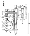
- a mixer is shown, the mixing of itself in a container flowable masses is used and consists of a mixing side M and a compensation side A is composed.
- the container as well as the flowable ones inside Masses are not shown.
- a rotating support 1 extends over the compensation side A and the mixing side M.
- a drive motor 10 is used in conjunction with a Gear 11 the drive of the carrier 1st
- the mixing device On the mixing side M, the mixing device has a rotating one arranged on the carrier 1 Container carrier 2, which can be driven against the direction of rotation of the carrier 1.
- the container carrier 2 is driven via a connection with the transmission 11 Drive shaft 12 and a between the container carrier 2 and the drive shaft 12 arranged angular gear 13.
- a lid 14 is detachably arranged on the container carrier 2.
- the mixing device On the compensating side A, the mixing device has a housing 3, in which a, not shown, active balancing mass can be absorbed in the form of a liquid medium.
- a Lid 15 is detachably connected to the housing 3.
- the housing 3 and the counter mass 4 are arranged on freely rotatable, axially fixed on the carrier Threaded spindles 5 stored.
- the threaded spindles 5 have two opposing ones Thread areas 6, 7, which are each substantially over half the length of the Extend threaded spindles 5.
- the threaded area 6 acts with the housing 3 and Thread area 7 interacts with the counter mass 4.
- When turning the threaded spindles 5 changes the distance between the housing 3 and an axis of rotation R of the mixing device and between the housing 3 and the counterweight 4. This means that depending on the direction of rotation of the threaded spindles 5, the housing 3 and the counter mass 4 are moved towards or away from each other.
- the Displacement of the housing 3 and the counter mass 4 serve four parallel to each other arranged threaded spindles 5, which are essentially in the peripheral region of the housing 3 and the counter mass 4 are arranged.
- the mixer is designed so that it is always in a balanced state located.
- the center of gravity of all masses resulting on the balancing side A of the mixing device is designated with SA and the associated radius with RA.
- SA The center of gravity of all masses resulting on the balancing side A of the mixing device
- RA the associated radius
- RM the resulting center of gravity of all masses with SM and the associated one Radius marked with RM.
- SA, SM The two focal points SA, SM are perpendicular to the line of rotation R extending.
- the products from mass and the associated Radius RA, RM are both on the compensation side A and on the mixing side M equal in amount to each other.
- the pull rod 16 has expansion areas that allow to put the tie rod 16 under a bias.
- the carrier 1 has four tie rods 16 arranged parallel to one another, which hold all the parts together enable the carrier 1 even at high rotational speed.
- the compensation side A of the mixing device shown in FIG. 3 shows this on the threaded spindles 5 mounted housing 3 and the counterweight 4, the empty housing 3rd and the counter mass 4 coincide in mass and center of gravity.
- the housing 3 has a center of gravity S1 and the counter mass 4 has a center of gravity S2.
- Both Focal points S1, S2 lie on a common beam S4, which is perpendicular to the axis of rotation R runs.
- the common center of gravity of the housing 3 and the counter mass 4 is designated S3 and lies between the focal points S1, S2 the common beam S4.
Landscapes
- Chemical & Material Sciences (AREA)
- Chemical Kinetics & Catalysis (AREA)
- Mixers With Rotating Receptacles And Mixers With Vibration Mechanisms (AREA)
- Confectionery (AREA)
- Mixers Of The Rotary Stirring Type (AREA)
Description
- Fig. 1
- ein erfindungsgemässes Mischgerät in der Seitenansicht;
- Fig. 2
- das Mischgerät gemäss Fig. 1 in der Draufsicht, teilweise geschnitten;
- Fig. 3
- die Ausgleichsseite des Mischgerätes gemäss der Fig. 1 und 2, in geschnittener Darstellung.
Claims (4)
- Mischgerät zum Mischen von sich in einem Behälter befindlichen fliessfähigen Massen mit einem rotierenden Träger (1), der einen entgegen der Drehrichtung des Trägers (1) rotierenden Behälterträger (2) für den Behälter auf einer Mischseite (M) und ein Gehäuse (3) für eine aktive Ausgleichsmasse auf einer der Mischseite (M) gegenüberliegenden Ausgleichsseite (A) aufweist, wobei die Momente der Mischseite (M) und Ausgleichsseite (A) ausgeglichen sind, dadurch gekennzeichnet, dass das Gehäuse (3) und eine am Träger (1) angeordnete, in Masse mit der Leermasse des Gehäuses (3) übereinstimmende Gegenmasse (4) auf der Ausgleichsseite (A) in radialer Richtung verschiebbar sind, wobei der Schwerpunkt (S1) des Gehäuses (3) und der Schwerpunkt (S2) der Gegenmasse (4) auf einem senkrecht zur Rotationsachse des Trägers (1) verlaufenden Strahl (S4) angeordnet sind und die Gegenmasse (4) entsprechend dem Betrag der Verschiebung des Gehäuses (3) entgegengesetzt zur Verschieberichtung des Gehäuses (3) versetzbar ist.
- Mischgerät nach Anspruch 1, dadurch gekennzeichnet, dass das Gehäuse (3) und die Gegenmasse (4) mit wenigstens einer am Träger (1) frei drehbaren, axial festen Gewindespindel (5) zusammenwirken, wobei der mit dem Gehäuse (3) zusammenwirkende Gewindebereich (6) gegenüber dem mit der Gegenmasse (4) zusammenwirkenden Gewindebereich (7) gegenläufig ist.
- Mischgerät nach Anspruch 2, dadurch gekennzeichnet, dass vier parallel zueinander angeordnete, mit dem Gehäuse (3) und der Gegenmasse (4) zusammenwirkende Gewindespindeln (5) vorgesehen sind.
- Mischgerät nach Anspruch 3, dadurch gekennzeichnet, dass die Gewindespindeln (5) über ein Uebertragungselement (8) miteinander verbunden sind.
Applications Claiming Priority (3)
| Application Number | Priority Date | Filing Date | Title |
|---|---|---|---|
| DE4443140 | 1994-12-03 | ||
| DE4443140A DE4443140A1 (de) | 1994-12-03 | 1994-12-03 | Mischgerät |
| PCT/EP1995/004747 WO1996017677A1 (de) | 1994-12-03 | 1995-12-01 | Mischgerät |
Publications (2)
| Publication Number | Publication Date |
|---|---|
| EP0794831A1 EP0794831A1 (de) | 1997-09-17 |
| EP0794831B1 true EP0794831B1 (de) | 1998-09-30 |
Family
ID=6534885
Family Applications (1)
| Application Number | Title | Priority Date | Filing Date |
|---|---|---|---|
| EP95941649A Expired - Lifetime EP0794831B1 (de) | 1994-12-03 | 1995-12-01 | Mischgerät |
Country Status (6)
| Country | Link |
|---|---|
| US (1) | US5746510A (de) |
| EP (1) | EP0794831B1 (de) |
| AT (1) | ATE171647T1 (de) |
| DE (2) | DE4443140A1 (de) |
| ES (1) | ES2123298T3 (de) |
| WO (1) | WO1996017677A1 (de) |
Cited By (1)
| Publication number | Priority date | Publication date | Assignee | Title |
|---|---|---|---|---|
| CN105032257A (zh) * | 2015-07-21 | 2015-11-11 | 张家港市兰航机械有限公司 | 一种颗粒混料机 |
Families Citing this family (20)
| Publication number | Priority date | Publication date | Assignee | Title |
|---|---|---|---|---|
| US6099160A (en) * | 1999-03-23 | 2000-08-08 | Flacktek, Inc. | Mixing system for mixing and dispensing reactive materials |
| CA2449416C (en) * | 2001-04-18 | 2011-02-22 | Nottingham-Spirk Partners, Llc | Improved container and lid assembly |
| DE10143439A1 (de) * | 2001-09-05 | 2003-03-20 | Hauschild & Co Kg | Mischvorrichtung zum Vermischen von flüssigen, fließfähigen oder pulverförmigen Materialien |
| DE60231330D1 (de) * | 2001-10-09 | 2009-04-09 | Sherwin Williams Co | Vorrichtung und verfahren zum mischen einer fluiddispersion, die in einem behälter mit entweder zylindrischer oder quadratischer form angeordnet ist |
| US6755565B2 (en) * | 2002-04-17 | 2004-06-29 | Flacktek, Inc. | Deep holder for dual asymmetric centrifugal mixing system |
| CA2428185C (en) * | 2002-05-13 | 2007-07-24 | The Sherwin-Williams Company | Apparatus and method for mixing a fluid dispersion disposed in a container having either a cylindrical or a square shape |
| KR100522736B1 (ko) * | 2002-11-25 | 2005-10-19 | 이장희 | 유성식 교반 및 탈포 장치 |
| US6953279B2 (en) * | 2003-01-21 | 2005-10-11 | Red Devil Equipment Company | Paint mixer with damping frame |
| US6945689B2 (en) * | 2003-04-18 | 2005-09-20 | Masterchem Industries, Llc | System for holding paint container |
| US6945690B2 (en) * | 2003-05-29 | 2005-09-20 | Masterchem Industries, Inc. | System for holding paint container |
| EP1527814A1 (de) * | 2003-10-28 | 2005-05-04 | CPS Color Equipment S.p.A. | Mischgehäuseanordnung zum Ausgleich vom Ungleichgewicht eines Mischbehälters |
| CA2461269A1 (en) * | 2004-03-16 | 2005-09-16 | Plastiques Gyf Ltee | Bladeless mixer |
| US7654730B2 (en) * | 2004-09-27 | 2010-02-02 | Ultrablend Llc | Ergonomic paint mixer |
| EP1674081A1 (de) * | 2004-12-23 | 2006-06-28 | KTB Tumorforschungsgesellschaft mbH | Herstellung von lipidbasierten Nanopartikeln unter Einsatz einer dualen asymmetrischen Zentrifuge |
| US7780339B2 (en) * | 2006-04-24 | 2010-08-24 | Red Devil Equipment Company | Vortex motion paint mixing machine |
| TW201302298A (zh) * | 2011-06-14 | 2013-01-16 | Hiroshige Ishii | 離心處理裝置 |
| DE102015100613A1 (de) * | 2015-01-16 | 2016-07-21 | Andreas Hettich Gmbh & Co. Kg | Rotor einer Dualen Zentrifuge |
| US9907319B2 (en) * | 2015-03-13 | 2018-03-06 | Steak 'n Shake Enterprises, Inc. | Dual-axis rotational mixer for food products |
| ITBO20150192A1 (it) * | 2015-04-17 | 2016-10-17 | Alfa Srl | Miscelatore per prodotti fluidi |
| US10328400B2 (en) * | 2016-09-29 | 2019-06-25 | L'oreal | Apparatus mixing blended composition for skin treatment |
Family Cites Families (13)
| Publication number | Priority date | Publication date | Assignee | Title |
|---|---|---|---|---|
| US1011929A (en) * | 1908-12-12 | 1911-12-19 | Frederic Ecaubert | Mixing and separating machine. |
| US3235173A (en) * | 1960-07-28 | 1966-02-15 | Unger Hans Peter Olof | Agitating and/or fractioning centrifuge |
| US3199775A (en) * | 1963-11-26 | 1965-08-10 | Kenneth G Drucker | Sedimentation rate centrifuge and method determining sedimentation rate |
| DE2001301A1 (de) * | 1969-01-14 | 1970-07-23 | Woodham Cecil H | Vorrichtung zum Mischen von zumindest zwei Substanzen |
| GB1387402A (en) * | 1971-03-02 | 1975-03-19 | Techno Med Ltd | Mixing process and apparatus |
| CA1132534A (en) * | 1978-09-25 | 1982-09-28 | John C. Gall | Material tumbler with non-perpendicular rotation axes |
| US4497581A (en) * | 1979-11-15 | 1985-02-05 | Miller Paint Equipment, Inc. | Paint shaker |
| JPS59105826A (ja) * | 1982-12-08 | 1984-06-19 | Fumitaka Hirozawa | 回巡容器装置 |
| CH666413A5 (de) * | 1985-06-20 | 1988-07-29 | Peter Reinhard | Geraet zur herstellung von abdruckmassen. |
| SU1472109A1 (ru) * | 1987-01-04 | 1989-04-15 | Всесоюзный научно-исследовательский проектно-конструкторский институт прикладной биохимии | Устройство дл перемешивани |
| DE8907335U1 (de) * | 1989-06-15 | 1990-10-18 | Espe Stiftung & Co Produktions- und Vertriebs KG, 8031 Seefeld | Mischvorrichtung für Pasten |
| FR2668079B1 (fr) * | 1990-10-18 | 1992-12-31 | Jouvin Jean Luc | Godet melangeur pour un malaxeur centrifuge planetaire, et malaxeur recevant de tels godets. |
| DE4239284A1 (de) * | 1992-11-23 | 1994-05-26 | Hilti Ag | Mischgerät für fließfähige Massen |
-
1994
- 1994-12-03 DE DE4443140A patent/DE4443140A1/de not_active Withdrawn
-
1995
- 1995-12-01 ES ES95941649T patent/ES2123298T3/es not_active Expired - Lifetime
- 1995-12-01 US US08/809,858 patent/US5746510A/en not_active Expired - Fee Related
- 1995-12-01 AT AT95941649T patent/ATE171647T1/de not_active IP Right Cessation
- 1995-12-01 EP EP95941649A patent/EP0794831B1/de not_active Expired - Lifetime
- 1995-12-01 DE DE59503810T patent/DE59503810D1/de not_active Expired - Fee Related
- 1995-12-01 WO PCT/EP1995/004747 patent/WO1996017677A1/de not_active Ceased
Cited By (1)
| Publication number | Priority date | Publication date | Assignee | Title |
|---|---|---|---|---|
| CN105032257A (zh) * | 2015-07-21 | 2015-11-11 | 张家港市兰航机械有限公司 | 一种颗粒混料机 |
Also Published As
| Publication number | Publication date |
|---|---|
| WO1996017677A1 (de) | 1996-06-13 |
| DE4443140A1 (de) | 1996-06-05 |
| ES2123298T3 (es) | 1999-01-01 |
| EP0794831A1 (de) | 1997-09-17 |
| DE59503810D1 (de) | 1998-11-05 |
| US5746510A (en) | 1998-05-05 |
| ATE171647T1 (de) | 1998-10-15 |
Similar Documents
| Publication | Publication Date | Title |
|---|---|---|
| DE4443140A1 (de) | Mischgerät | |
| EP0599783B1 (de) | Mischgerät für fliessfähige Massen | |
| DE3701802C2 (de) | ||
| DE3242541C2 (de) | ||
| DE19712905C2 (de) | Planetenkugelmühle | |
| EP1293245B1 (de) | Mischvorrichtung zum Vermischen von flüssigen, fliessfähigen oder pulverförmigen Materialien | |
| DE2357629A1 (de) | Vorrichtung zum ausgleich der unwucht eines rotierenden koerpers, insbesondere einer schleifscheibe | |
| DE3828285C2 (de) | Zentrifuge | |
| DE2631623A1 (de) | Ruehrwerksmuehle | |
| EP2861350B1 (de) | Kugelmühle mit räumlicher unwuchtkompensation | |
| EP0280897A2 (de) | Walzenmühle | |
| CH635430A5 (de) | Dosiergeraet. | |
| DE3444420C2 (de) | ||
| EP0223851B1 (de) | Vorrichtung zum mischen von gut | |
| DE2631826A1 (de) | Zentrifugalmuehle | |
| DE1782177C2 (de) | Vorrichtung für das Durchwirken eines oder mehrerer Stoffe | |
| EP3350107A1 (de) | Behältertransporteur | |
| DE1211904B (de) | Ruehrwerksmuehle | |
| DE932720C (de) | Antriebsvorrichtung fuer in Absetzbehaeltern kreisende Kratzer | |
| DE2119314A1 (de) | Vorrichtung zum Mischen und/oder Trocknen von Stoffen | |
| EP0667289A1 (de) | Vorrichtung zum Egalisieren von nichtfixiertem, teiligen Verpackungsgut in Verpackungsschachteln und/oder Verpackungsbeuteln | |
| DE552049C (de) | Knet- und Mischmaschine mit durch die Wandung einer Drehtrommel hindurchragenden Mischstaeben | |
| DE4223523A1 (de) | Schleifscheibe für die Oberflächenbearbeitung von Werkstücken | |
| DE2559177C3 (de) | Mischer, insbesondere Heiz- und Kühlmischer für die chemische Verfahrenstechnik | |
| EP0406480B1 (de) | Rotationsvibrator |
Legal Events
| Date | Code | Title | Description |
|---|---|---|---|
| PUAI | Public reference made under article 153(3) epc to a published international application that has entered the european phase |
Free format text: ORIGINAL CODE: 0009012 |
|
| 17P | Request for examination filed |
Effective date: 19961223 |
|
| AK | Designated contracting states |
Kind code of ref document: A1 Designated state(s): AT BE CH DE DK ES FR GB GR IE IT LI LU NL PT SE |
|
| GRAG | Despatch of communication of intention to grant |
Free format text: ORIGINAL CODE: EPIDOS AGRA |
|
| 17Q | First examination report despatched |
Effective date: 19971106 |
|
| GRAG | Despatch of communication of intention to grant |
Free format text: ORIGINAL CODE: EPIDOS AGRA |
|
| GRAH | Despatch of communication of intention to grant a patent |
Free format text: ORIGINAL CODE: EPIDOS IGRA |
|
| GRAH | Despatch of communication of intention to grant a patent |
Free format text: ORIGINAL CODE: EPIDOS IGRA |
|
| RAP1 | Party data changed (applicant data changed or rights of an application transferred) |
Owner name: FS KUNSTSTOFFTECHNOLOGIE GMBH |
|
| GRAA | (expected) grant |
Free format text: ORIGINAL CODE: 0009210 |
|
| AK | Designated contracting states |
Kind code of ref document: B1 Designated state(s): AT BE CH DE DK ES FR GB GR IE IT LI LU NL PT SE |
|
| PG25 | Lapsed in a contracting state [announced via postgrant information from national office to epo] |
Ref country code: GR Free format text: LAPSE BECAUSE OF NON-PAYMENT OF DUE FEES Effective date: 19980930 |
|
| REF | Corresponds to: |
Ref document number: 171647 Country of ref document: AT Date of ref document: 19981015 Kind code of ref document: T |
|
| REG | Reference to a national code |
Ref country code: CH Ref legal event code: EP |
|
| REF | Corresponds to: |
Ref document number: 59503810 Country of ref document: DE Date of ref document: 19981105 |
|
| REG | Reference to a national code |
Ref country code: CH Ref legal event code: NV Representative=s name: PATENTANWAELTE SCHAAD, BALASS, MENZL & PARTNER AG |
|
| PG25 | Lapsed in a contracting state [announced via postgrant information from national office to epo] |
Ref country code: LU Free format text: LAPSE BECAUSE OF NON-PAYMENT OF DUE FEES Effective date: 19981201 |
|
| REG | Reference to a national code |
Ref country code: IE Ref legal event code: FG4D Free format text: GERMAN |
|
| GBT | Gb: translation of ep patent filed (gb section 77(6)(a)/1977) |
Effective date: 19981201 |
|
| PG25 | Lapsed in a contracting state [announced via postgrant information from national office to epo] |
Ref country code: PT Free format text: LAPSE BECAUSE OF FAILURE TO SUBMIT A TRANSLATION OF THE DESCRIPTION OR TO PAY THE FEE WITHIN THE PRESCRIBED TIME-LIMIT Effective date: 19981230 |
|
| PG25 | Lapsed in a contracting state [announced via postgrant information from national office to epo] |
Ref country code: DK Free format text: LAPSE BECAUSE OF FAILURE TO SUBMIT A TRANSLATION OF THE DESCRIPTION OR TO PAY THE FEE WITHIN THE PRESCRIBED TIME-LIMIT Effective date: 19981231 |
|
| REG | Reference to a national code |
Ref country code: ES Ref legal event code: FG2A Ref document number: 2123298 Country of ref document: ES Kind code of ref document: T3 |
|
| ET | Fr: translation filed | ||
| PG25 | Lapsed in a contracting state [announced via postgrant information from national office to epo] |
Ref country code: IE Free format text: LAPSE BECAUSE OF NON-PAYMENT OF DUE FEES Effective date: 19990504 |
|
| REG | Reference to a national code |
Ref country code: IE Ref legal event code: FD4D |
|
| PLBE | No opposition filed within time limit |
Free format text: ORIGINAL CODE: 0009261 |
|
| STAA | Information on the status of an ep patent application or granted ep patent |
Free format text: STATUS: NO OPPOSITION FILED WITHIN TIME LIMIT |
|
| 26N | No opposition filed | ||
| PGFP | Annual fee paid to national office [announced via postgrant information from national office to epo] |
Ref country code: GB Payment date: 19991130 Year of fee payment: 5 |
|
| PGFP | Annual fee paid to national office [announced via postgrant information from national office to epo] |
Ref country code: SE Payment date: 19991214 Year of fee payment: 5 |
|
| PGFP | Annual fee paid to national office [announced via postgrant information from national office to epo] |
Ref country code: FR Payment date: 19991215 Year of fee payment: 5 Ref country code: ES Payment date: 19991215 Year of fee payment: 5 |
|
| PGFP | Annual fee paid to national office [announced via postgrant information from national office to epo] |
Ref country code: CH Payment date: 19991223 Year of fee payment: 5 |
|
| PGFP | Annual fee paid to national office [announced via postgrant information from national office to epo] |
Ref country code: NL Payment date: 19991227 Year of fee payment: 5 |
|
| PGFP | Annual fee paid to national office [announced via postgrant information from national office to epo] |
Ref country code: BE Payment date: 19991229 Year of fee payment: 5 |
|
| PGFP | Annual fee paid to national office [announced via postgrant information from national office to epo] |
Ref country code: DE Payment date: 19991230 Year of fee payment: 5 Ref country code: AT Payment date: 19991230 Year of fee payment: 5 |
|
| PG25 | Lapsed in a contracting state [announced via postgrant information from national office to epo] |
Ref country code: GB Free format text: LAPSE BECAUSE OF NON-PAYMENT OF DUE FEES Effective date: 20001201 Ref country code: AT Free format text: LAPSE BECAUSE OF NON-PAYMENT OF DUE FEES Effective date: 20001201 |
|
| PG25 | Lapsed in a contracting state [announced via postgrant information from national office to epo] |
Ref country code: SE Free format text: LAPSE BECAUSE OF NON-PAYMENT OF DUE FEES Effective date: 20001202 |
|
| PG25 | Lapsed in a contracting state [announced via postgrant information from national office to epo] |
Ref country code: LI Free format text: LAPSE BECAUSE OF NON-PAYMENT OF DUE FEES Effective date: 20001231 Ref country code: CH Free format text: LAPSE BECAUSE OF NON-PAYMENT OF DUE FEES Effective date: 20001231 Ref country code: BE Free format text: LAPSE BECAUSE OF NON-PAYMENT OF DUE FEES Effective date: 20001231 |
|
| BERE | Be: lapsed |
Owner name: FS KUNSTSTOFFTECHNOLOGIE G.M.B.H. Effective date: 20001231 |
|
| PG25 | Lapsed in a contracting state [announced via postgrant information from national office to epo] |
Ref country code: NL Free format text: LAPSE BECAUSE OF NON-PAYMENT OF DUE FEES Effective date: 20010701 |
|
| GBPC | Gb: european patent ceased through non-payment of renewal fee |
Effective date: 20001201 |
|
| EUG | Se: european patent has lapsed |
Ref document number: 95941649.6 |
|
| REG | Reference to a national code |
Ref country code: CH Ref legal event code: PL |
|
| PG25 | Lapsed in a contracting state [announced via postgrant information from national office to epo] |
Ref country code: FR Free format text: LAPSE BECAUSE OF NON-PAYMENT OF DUE FEES Effective date: 20010831 |
|
| NLV4 | Nl: lapsed or anulled due to non-payment of the annual fee |
Effective date: 20010701 |
|
| REG | Reference to a national code |
Ref country code: FR Ref legal event code: ST |
|
| PG25 | Lapsed in a contracting state [announced via postgrant information from national office to epo] |
Ref country code: DE Free format text: LAPSE BECAUSE OF NON-PAYMENT OF DUE FEES Effective date: 20011002 |
|
| PG25 | Lapsed in a contracting state [announced via postgrant information from national office to epo] |
Ref country code: ES Free format text: LAPSE BECAUSE OF NON-PAYMENT OF DUE FEES Effective date: 20011202 |
|
| REG | Reference to a national code |
Ref country code: ES Ref legal event code: FD2A Effective date: 20020112 |
|
| PG25 | Lapsed in a contracting state [announced via postgrant information from national office to epo] |
Ref country code: IT Free format text: LAPSE BECAUSE OF NON-PAYMENT OF DUE FEES Effective date: 20051201 |