EP0791173B1 - Fur medizinische diagnose anzuwendende mikrogele und verfahren zu deren herstellung und verwendung - Google Patents
Fur medizinische diagnose anzuwendende mikrogele und verfahren zu deren herstellung und verwendung Download PDFInfo
- Publication number
- EP0791173B1 EP0791173B1 EP95939836A EP95939836A EP0791173B1 EP 0791173 B1 EP0791173 B1 EP 0791173B1 EP 95939836 A EP95939836 A EP 95939836A EP 95939836 A EP95939836 A EP 95939836A EP 0791173 B1 EP0791173 B1 EP 0791173B1
- Authority
- EP
- European Patent Office
- Prior art keywords
- gel
- microgel
- substrate
- adhesive
- solid particles
- Prior art date
- Legal status (The legal status is an assumption and is not a legal conclusion. Google has not performed a legal analysis and makes no representation as to the accuracy of the status listed.)
- Expired - Lifetime
Links
Images




Classifications
-
- G—PHYSICS
- G01—MEASURING; TESTING
- G01N—INVESTIGATING OR ANALYSING MATERIALS BY DETERMINING THEIR CHEMICAL OR PHYSICAL PROPERTIES
- G01N27/00—Investigating or analysing materials by the use of electric, electrochemical, or magnetic means
- G01N27/26—Investigating or analysing materials by the use of electric, electrochemical, or magnetic means by investigating electrochemical variables; by using electrolysis or electrophoresis
- G01N27/416—Systems
- G01N27/447—Systems using electrophoresis
- G01N27/44704—Details; Accessories
- G01N27/44743—Introducing samples
-
- G—PHYSICS
- G01—MEASURING; TESTING
- G01N—INVESTIGATING OR ANALYSING MATERIALS BY DETERMINING THEIR CHEMICAL OR PHYSICAL PROPERTIES
- G01N27/00—Investigating or analysing materials by the use of electric, electrochemical, or magnetic means
- G01N27/26—Investigating or analysing materials by the use of electric, electrochemical, or magnetic means by investigating electrochemical variables; by using electrolysis or electrophoresis
- G01N27/416—Systems
- G01N27/447—Systems using electrophoresis
- G01N27/44704—Details; Accessories
-
- G—PHYSICS
- G01—MEASURING; TESTING
- G01N—INVESTIGATING OR ANALYSING MATERIALS BY DETERMINING THEIR CHEMICAL OR PHYSICAL PROPERTIES
- G01N27/00—Investigating or analysing materials by the use of electric, electrochemical, or magnetic means
- G01N27/26—Investigating or analysing materials by the use of electric, electrochemical, or magnetic means by investigating electrochemical variables; by using electrolysis or electrophoresis
- G01N27/416—Systems
- G01N27/447—Systems using electrophoresis
- G01N27/44704—Details; Accessories
- G01N27/44747—Composition of gel or of carrier mixture
Definitions
- DNA sequencing may be carried out using automated systems designed for laboratory application. Methods and apparatus for sequencing of DNA are described in U.S. Patents Nos. 4,811,218; 4,823,007; 5,062,942; 5,091,652; 5,119,316 and 5,122,345.
- the general methodology employed in these systems involves breaking up the sample DNA using restriction endonucleases; amplifying (for example with PCR) the restriction fragment of interest; combining the amplified DNA with a sequencing primer which may be the same as or different from the amplification primers; extending the sequencing primer in the presence of normal nucleotide (A, C, G, and T) and a chain-terminating nucleotide, such as a dideoxynucleotide, which prevents further extension of the primer once incorporated; and analyzing the product for the length of the extended fragments obtained. Analysis of fragments may be done by electrophoresis, for example on a polyacrylamide gel.
- the gel holder comprises
- the spacing between the substrates can also be established using a plurality of beads disposed on the surface of the substrates within the gel compartment.
- the edges can be scaled by adhesive, or by adhesive-coated plastic films of appropriate thickness. Particles may also be disposed both within the adhesive and within the gel compartment.
- the microgel shown in Fig. 1 can be made by a "squash-filling" process as follows. First, the spacer 3 is adhered to the bottom substrate 1. The area of the gel compartment 4 is then filled with unpolymerized or partially polymerized gel, and the top substrate 2 is pressed down over the top. The unpolymerized gel fills the gel compartment 4, with any excess gel being squeezed out between around the edges of the substrate. The gel is then polymerized, and the excess is trimmed off.
- Fig. 2 shows an exploded view of a second embodiment of a microgel in accordance with the invention which is adapted to be filled by a different technique.
- the spacer 23 only extends along three sides of the bottom substrate 1, leaving an opening 24 along the fourth edge.
- electrodes 26 and 27 may be deposited as a film directly on the top or bottom substrates.
- Suitable electrode materials are thin films of conductive materials such as indium tin oxide (ITO) or platinum.
- Solution buffered electrodes i.e. electrodes in which the electrical contact between a conventional metallic (e.g. platinum) electrode and the gel is indirect, and is mediated by a concentrated electrolyte solution, may also be used.
- a microgel of the type shown in Fig. 2 can be made by first adhering the bottom substrate 1, the spacer 23 and the top substrate 2 together to form a gel holder assembly.
- the gel holder assembly is then placed in a chamber and positioned vertically with the opening 24 directed downwards over a reservoir of unpolymerized gel.
- the chamber is then evacuated, the gel holder assembly is lowered to immerse the opening in the unpolymerized gel, and a gas is reintroduced into the chamber at positive pressure to drive the gel into the gel compartment 4 of the gel holder assembly.
- No slots are necessary in the top substrate of this embodiment, because the gel is exposed through the opening 24, permitting edge loading of the gel, although one or more slots in the top substrate may be provided if desired for introduction of sample or electrodes.
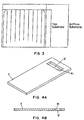
- a third embodiment of the invention is shown in Fig. 3.
- spacers have been used to create lane markers 30 within the body of the gel.
- Such lane markers may be incorporated to separate every lane, every fourth lane, or at such other intervals as may be preferred by the user.
- the gel is separated into a number of lanes of equal width. The number of these lanes is determined by the formula (A/4), where A is the number of useable sample loading sites in the gel.
- top substrate When the top substrate is shorter than the bottom substrate as shown in Fig. 3, it has been found to be advantageous to extend the lanes beyond the end of the top substrate across at least a part of the extending portion of the bottom substrate. This results in all lanes filling individually from the bottom up, and eliminates the possibility of unpolymerized gel from one lane spilling over into an adjacent lane and causing a bubble to form in the middle of that lane.
- a microgel using a top substrate cut as shown in Figs 4A and 4B is preferably formed using a gel forming insert of the type shown in Fig. 5A.
- This insert has a base portion 1 and an insert portion 52.
- the insert portion 52 is notched at each end, such that it is narrower than the base portion.
- the size of each notch is from 2-4 mm to 5mm.
- the free edge of the insert portion is beveled to match the bevel formed in the lower edge 31 of the window 5', and the overall size of the insert is selected to permit insertion of the insert into the window 5'.
- suitable dimensions are 12.5 cm wide, 1.5 cm in total height and 1 mm in thickness.
- a tab or handle may be placed on one surface of the base portion 31 to facilitate removal.
- the insert has a substantially rectangular base portion 61 having two long edges and two short edges; and a plurality of fingers 62 extending from one long edge of the base portion.
- Each of the fingers preferably has a width of from 0.5 to 3 mm.
- the fingers are evenly spaced at intervals of 2 to 7 mm in a region along the long edge of the base portion staring and ending at a point from 2 to 4 mm from the adjacent short edge of the base portion so that the fingers fit within the trough.
- the fingers further have a 30-60° bevel at the distal end thereof to match the bevel of the loading insert and the lower edge of the window.
- a second and alternative method of preparing and loading a microgel requires forming the microgel in the presence of a polymerization comb insert which has a series of flattened extensions which will form wells for the loading of sample on the gel.
- the polymerization comb insert replaces the gel forming insert during the microgel filling and polymerization process.
- the dimensions of the polymerization comb insert arc identical to the gel forming insert, except that instead of having a flat bottom edge beveled at a 45 degree angle to be complementary to the bottom edge of the window in the top substrate, a notch of about 2mm width and about 5 mm depth is made at intervals, e.g.
- the polymerization comb insert may be scaled in place with adhesive tape such that the entire window is completely covered. An opening for the air holes is then introduced into the adhesive tape. Solution is then injected into the microgel holder. The solution fills the microgel compartment and flows into the gaps in the teeth of the Polymerization Comb. Excess solution bleeds out of the air holes. The solution may then be polymerized with UV induced catalysis as described in the invention.
- the adhesive tape and the polymerization comb insert arc gently removed, leaving a row of gel columns vertically disposed against the bottom substrate.
- the gel columns act to define wells which can be used to separate samples loaded by the conventional methods.
- Microgels are found to have improved loading and using qualities if prior to the construction of the microgel holder, the gel compartment faces of the top substrate and bottom substrate are treated with Bind Silane (Pharmacia).
- Figs. 7A and 7B shows alternative designs for filling plug and loading combs useful when the lane dividers are present on the extended portion of the bottom substrate (Fig. 3).
- grooves 101 arc formed along one surface of the inserts to accommodate the lane dividers.
- the grooves arc slightly wider than the lane dividers to allow for air and excess gel to escape during the filling process.
- the top and bottom substrates of the microgels of the invention are preferably transparent sheets of glass.
- 1 mm thick low-fluorescing glass is a preferred material for use as the top and bottom substrate of the invention.
- 1 mm Borosilicate glass which has greater ultraviolet light transparency is another preferred material.
- Other materials such as plastics may also be used, however, provided they do not fluoresce strongly in a region which would interfere with the detection of a luminescent label on the nucleic acid polymer being sequenced or inhibit the polymerization of the gel.
- the spacers 3 in the microgels of the invention serve to create a gap between the top and bottom substrates to establish the gel compartment.
- spacers are preferably selected such that this gap is between about 25 and 250 ⁇ m, more preferably 25 to 100 ⁇ m. Smaller gaps are not really practical because of the greater care must be taken during fabrication, for example the use of clean room procedures to prevent dust particles which may be large relative to the desired gap from contaminating the surface of the substrate. Also, the extent to which both substrates are flat becomes more important as gap size decrease. Lastly, the amount of sample loaded onto the gel may need to be reduced to avoid loss of the gels resolving ability which means that there will be a smaller emitted signal from the sample to detect.
- Gaps larger than 250 mm can be used, but may be less desirable because the electrical resistance of a gel of any given composition increases as the gap size increases. This means that larger currents and hence greater resistive heating of the gel will occur for a given electric field strength in a thicker gel.
- the spacer is formed by applying adhesive to one or both substrates, it is necessary to build up an adhesive layer that is essentially the same thickness as the gap. It may be difficult to find an adhesive which is viscous enough to bridge the openings between spacers particles, has minimal flow out, permits settling of the substrate onto the spacers and minimizes voids formed in the application process.
- spacer useful in the invention is a polymeric film that is affixed to the top or bottom substrate with an adhesive.
- an adhesive for example, vinyl films coated with an acrylate adhesive can be cut to the desired size and pattern to form spacers.
- Suitable vinyl films include 1, 2 and 4 mil films sold by 3M under the tradename SCOTCHCAL.
- Spacers can also be formed by screen printing a slurry of particles in a hardenable material in the desired pattern onto the top or bottom substrate.
- a UV-curable and/or thermally-curable acrylate adhesive slurried with graded silica particles of the appropriate size to define the desired gap between the substrates is a preferred material for use in forming a spacer by this mechanism.
- Suitable adhesives include Loctite CHIPBONDERTM # 346, 347, 360 and 3603, IMPRUVTM 349, 363, 365 and 366 and General Purpose Ultraviolet Adhesive 352; and Minico® M07950-R acrylate adhesive.
- the glass powder or "frit” will advantageously have a melting temperature of about 400 to 500 °C, while the melting temperatures of the solid particles beads and the substrates will be form 600 to 800 °C. Notwithstanding this difference in melting temperature, care should be taken to match the thermal expansion coefficients of the glass powder, substrates and solid particles to avoid fractures or voids due to shrinkage on cooling. Acceptable results are achieved when the thermal expansion coefficients of the materials are within about 10% of each other.
- Dispersions of particles in an adhesive can also be applied using a robotic glue gun which paints the adhesive onto the glass substrate in the desired pattern. This has the advantage over screen printing that nothing actually touches the substrate other than the adhesive.
- Spacers can be formed using this approach on a single substrate. It is preferred, however, to print matching patterns on both the top and bottom substrate that are aligned and pressed together to form the spacer between the two substrates. While this method introduces the need for careful alignment, it has been found that it has the advantage of reducing the formation of bubbles and voids in the spacer lines, thus leading to a more consistent product.
- the spacing between the two substrates may be further defined and maintained by a dispersion of solid beads within the gels itself. This can be achieved by evenly spreading a slurry of beads. for example glass beads, of the appropriate size in a volatile solvent onto the interior surface of one of the substrates prior to the formation of the gel holder. The solvent is evaporated off, leaving the solid particles distributed on the surface of the substrate.
- the gels of the invention offer the further advantage of high consistency from one gel to the next. This advantages is principally derived from the use of carefully controlled spacer thicknesses in a mass production approach.
- Microgels in accordance of the invention can be used to analyze quickly and accurately a mixture of fluorescently-labeled oligonucleotide fragments of differing lengths. Basically, this process involves first loading the mixture onto an origination site on a microgel in accordance with the invention, and applying a potential to the electrophoresis gel whereby a current flows through the electrophoresis gel and transports the oligonucleotide fragments in the mixture away from the origination site and through a monitoring site remote from the origination site on the gel. Fluorescent emission from oligonucleotides passing the monitoring point is then detected.
- electrode configurations for applying the potential to the gel may be of several types.
- a field of up to 350 V/cm, preferably 150-350 V/cm is applied using a standard electrophoresis power supply.
- This high field strength offers the advantages of rapid migration of the fragments through the gel, resulting in a reduced time to analyze the fragments.
- the rapid migration also reduces the impact of diffusion of fragments in the gel, which yields better resolution.
- Field strengths of this magnitude arc not practically useful in a macrogel, i.e., a gel having a thickness of 0.35 mm (350 mm) or greater, because of the enormous current flow and resultant heating that would occur.
- Fig. 8 shows one apparatus for use in analyzing oligonuclcotide mixtures.
- a light source 41 such as an argon ion laser, shines an excitation beam 40 approximately parallel to the surface of the microgel 42.
- the excitation beam passes through a beam expander 43 and an interference filter 44 that removes undesired wavelengths of light, and then strikes a diffracting mirror 45 selected to reflect light of the excitation wavelength and transmit light of the wavelength at which the fluorescent marker emits.
- the diffracting mirror 45 reflects the excitation beam 40 onto the microgel 42.
- fluorescently labeled oligonucleotides pass through the beam, light is emitted in all directions, including back towards the diffracting mirror 45.
- This light 46 passes through the diffracting mirror 45, an interference filter 47 selected to isolate the emission wavelength from scatter and nonspecific fluorescence, and a lens 48 that focuses the beam 46 on a photomultiplier tube 49.
- Fig. 9 shows an alternative apparatus for analyzing oligonucleotide mixtures in accordance with the invention.
- excitation beam 80 from light source 81 strikes the surface of the microgel 82 at an angle a, generally from 45 to 65 degrees.
- Light 86 emitted in the direction of a photomultiplier tube 89, optionally passing through collection lenses and filters (not shown).
- the invention is not limited to the use of argon ion lasers as the light source. While the argon ion laser is convenient because its emission at 488 nm is effective to excite fluorescein, the use of other labels, with different absorption maxima may argue for the use of other type of lasers, or for the use of conventional light sources such as mercury or xenon lamps, combined with appropriate filters.
- microgel holders of the present invention may in principle be used to form microgels using any type of gel forming material, including agarose gels.
- the preferred gel material is a polyacrylamide gel.
- Polyacrylamide microgels in accordance with the invention may be formed using either a chemical cross-linking agent catalyst such as TEMED and ammonium persulfate or a photoactivated cross-linking system such as riboflavin and ultraviolet light, or methylene blue and blue (450 nm) light.
- photopolymerized gels are used in combination with a photocurablc adhesive
- a gel Prior to the use of a gel for analysis of oligonucleotide fragments, it may be desirable to pre-run the gel, i.e., to apply a potential gradient with running buffer, but without the application of a sample. Such a pre-run may remove excess reactants from the polymerization reaction which could interfere with migration or detection of the oligonucleotides.
- a pre-run may remove excess reactants from the polymerization reaction which could interfere with migration or detection of the oligonucleotides.
- some constituents used in the running buffer notably urea, may tend to degrade acrylamide gels, the shelf life of the microgel can be improved by introducing these components just before the actual running of the analysis.
- a test sample was prepared containing a mixture of 0.1 ng/ml of a 30-mer having the sequence and 0.1 ng/ml of a 31-mer having the sequence
- These oligonucleotides were synthesized by a commercial supplier of custom oligonucleotides (Oligos Etc.) in accordance with the inventors' instructions, and were labeled with fluorescein at the 5'-end.
- nl of the test sample (containing ⁇ 100 femtomoles of each oligonucleotide) was edge loaded onto the top of the gel using a capillary.
- a field of 100 V/cm was then applied to the gel by laying an electrode consisting of a 0.25 mm thick strip of indium tin oxide, 35 mm X 8 mm in size, across each end of the polymerized gel, then connecting the electrodes to an electrophoresis power supply.
- An argon ion laser detection system of the type shown in Fig. 8 was used to detect passage of the fluorescein-labeled oligonucleotides past a point located 55-65 mm from the origin.
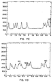
- the signal detected by the photomultiplier tube is shown in Fig. 10. The signal was resolved into two peaks corresponding to the 30-mer (peak A) and the 31-mer (peak B) within a run time of 3 minutes.
- a UV activated adhesive matrix was prepared using Minico® M07950-R acrylate adhesive from Emerson & Cuming Inc., Woburn. MA, mixed with 2% by weight Sigma® glass beads (106 micron and finer) filtered to select beads of a size of 45 to 53 microns.
- the adhesive matrix was screen printed onto the bottom substrate in the pattern shown in Fig. 3.
- the top substrate was then positioned on top of the bottom substrate as illustrated in Fig. 3.
- the substrates were then exposed to 20 Watts UVA light (wavelength 315-385 nm) to initiate curing of the adhesive and to bond the two substrates together.
- the gel holder was placed horizontally in a rectangular filling device of the type described in U.S. Patent Application No. 08/332,892 and the concurrently filed CIP thereof, which are incorporated herein by reference. Briefly, the microgel holder was laid horizontally in a quadrilateral filling frame, and placed on the upper shelf within a filling cabinet. In the cabinet, a polyacrylamide gel forming solution was driven into the gel holder, which was then exposed to ultraviolet light from 20 W UVA-lamps disposed on the interior of the filling cabinet for a period of time sufficient to polymerize the gel.
- the gel forming solution used contained 6% acrylamide (19:1 bis-acrylamide), 7 M urea in 0.6 X TBE and 10 ppm riboflavin.
- the riboflavin was introduced by adding 10 ⁇ l of a 0.4% aqueous riboflavin solution to 25 ml of acrylamide solution.
- a UV activated adhesive matrix of the type described in Example 2 was screen printed onto the bottom substrate in the pattern shown in Fig. 2.
- One ml of a slurry of 100% ethanol and 1% by weight glass beads (45 to 53 microns) was applied to and evenly distributed across the bottom substrate.
- the top substrate was positioned over the bottom substrate as illustrated in Fig. 2, and the substrates were pressed together.
- the substrates were then exposed to 20 Watts UV lights (315-385 nm) to initiate curing if the adhesive, and to bond the two substrates together to form a gel holder.
- a microgel was prepared as in EXAMPLE 2, using the Insert Panel during the polymerization of the microgel.
- the Insert Panel was carefully removed and replaced by the Loading Insert.
- the microgel holder was mounted vertically in an electrophoresis apparatus. 3 ⁇ l of a prepared solution containing the products of a completed fluorescein-labeled ddT DNA sequencing reaction of M13 template DNA, with methylene blue and xylene cyanol as additional visible separation markers, was pipetted into a loading well.
- a TBE solution electrode was formed by gasket scaling the microgel window against a TBE reservoir containing a platinum electrode.
- the "bottom" of the microgel was immersed in a TBE reservoir containing a platinum electrode.
- the back of the microgel holder was secured against an alumina plate by vacuum suction in order to dissipate heat during the electrophoresis.
- An electric potential was applied between the two electrodes, generating an electric field of 300 V/cm through the microgel.
- the paste is screen printed onto one glass substrate plate in the desired pattern, for example the patterns shown in Fig. 2 or Fig. 3.
- the substrate is then heated to 125 °C for 10 minutes and 320 °C for 10 minutes to prepare the paste for sealing.
- the plate is put in a furnace at 450 ° C for 25 minutes to pre-fuse the glass powder.
- a second substrate plate is then placed on top of the first plate with the pre-fused material sandwiched in between.
- the whole assembly is then placed in a furnace at 470 °C for another 25 minutes, causing final binding of the plates together.
- pressure is applied to the outside faces of the plates. This pressure may be generated by clamping, by placing a weight onto the uppermost substrate or using an air driven piston directed from the top, downwards against the substrates.
Landscapes
- Health & Medical Sciences (AREA)
- Life Sciences & Earth Sciences (AREA)
- Chemical & Material Sciences (AREA)
- Molecular Biology (AREA)
- Analytical Chemistry (AREA)
- Pathology (AREA)
- Electrochemistry (AREA)
- Physics & Mathematics (AREA)
- Chemical Kinetics & Catalysis (AREA)
- Biochemistry (AREA)
- General Health & Medical Sciences (AREA)
- General Physics & Mathematics (AREA)
- Immunology (AREA)
- Dispersion Chemistry (AREA)
- Apparatus Associated With Microorganisms And Enzymes (AREA)
- Medicines Containing Antibodies Or Antigens For Use As Internal Diagnostic Agents (AREA)
- Measuring Or Testing Involving Enzymes Or Micro-Organisms (AREA)
- Investigating Or Analysing Biological Materials (AREA)
- Peptides Or Proteins (AREA)
Claims (60)
- Mikrogelhalter, der umfasst(a) ein oberes Substrat;(b) ein unteres Substrat;(c) Mittel zum dichten Verbinden des oberen Substrats mit dem unteren Substrat, um einen Gelraum mit einer Dicke von 250 Mikrometern oder weniger auszubilden, wobei die Mittel zu dichten Verbinden eine durch sie hindurch gehende Öffnung zum Füllen des Gelraumes mit einem nichtpolymerisierten Gel aufweisen;
und(d) eine Vielzahl fester Partikel, wobei die festen Partikel zwischen dem oberen und dem unteren Substrat angeordnet sind und einen mittleren Durchmesser aufweisen, der im Wesentlichen der Dicke des Gelraumes entspricht. - Mikrogelhalter nach Anspruch 1, dadurch gekennzeichnet, dass das Mittel zum dichten Verbinden der Substrate einen Klebstoff umfasst, der zwischen dem oberen und dem unteren Substrat entlang von zumindest zwei gegenüberliegenden Kanten des oberen und des unteren Substrats aufgetragen wird.
- Mikrogelhalter nach Anspruch 2, dadurch gekennzeichnet, dass zumindest ein Teil der festen Partikel in dem Klebstoff dispergiert ist.
- Mikrogelhalter nach Anspruch 1 oder 2, dadurch gekennzeichnet, dass die festen Partikel mit zumindest einem der Substrate mit Hilfe eines niedrig schmelzenden Glases verbunden sind.
- Mikrogelhalter nach einem der Ansprüche 1 bis 4, dadurch gekennzeichnet, dass der Gelraum in eine Vielzahl von Bahnen geteilt ist.
- Mikrogelhalter nach Anspruch 5, dadurch gekennzeichnet, dass der Gelraum durch Klebstofflinien, die zumindest einen Teil der festen Partikel enthalten, in Bahnen geteilt ist.
- Mikrogelhalter nach einem der Ansprüche 2, 3 oder 5 bis 6, dadurch gekennzeichnet, dass der Klebstoff ein Acrylatklebstoff ist.
- Mikrogelhalter nach einem der Ansprüche 2, 3 oder 5 bis7, dadurch gekennzeichnet, dass der Klebstoff ein photoaktivierter Klebstoff ist.
- Mikrogelhalter nach einem der Ansprüche 1 bis 8, dadurch gekennzeichnet, dass der Gelraum eine Dicke von 25 bis 250 Mikrometern aufweist.
- Mikrogelhalter nach einem der Ansprüche 1 bis 8, dadurch gekennzeichnet, dass der Gelraum eine Dicke von 25 bis 100 Mikrometern aufweist.
- Mikrogelhalter nach einem der Ansprüche 1 bis 10, dadurch gekennzeichnet, dass in das obere Substrat eine Probeneinbringöffnung geschnitten ist.
- Mikrogelhalter nach Anspruch 11, der weiterhin einen entfernbaren Klebestreifen umfasst, der über der Probeneinbringöffnung angebracht ist.
- Mikrogelhalter nach einem der Ansprüche 1 bis 12, dadurch gekennzeichnet, dass der Mikrogelhalter ein Wegwerf-Mikrogelhalter ist.
- Mikrogel zur elektrophoretischen Trennung von Proben, das umfasst(a) ein oberes Substrat;(b) ein unteres Substrat;(c) Mittel zum dichten Verbinden des oberen Substrats mit dem unteren Substrat, um einen Gelraum mit einer Dicke von 250 Mikrometern oder weniger auszubilden, wobei die Mittel zu dichten Verbinden eine durch sie hindurch gehende Öffnung zum Füllen des Gelraumes mit einem nichtpolymerisierten Elektrophoresegel aufweisen;(d) eine Vielzahl fester Partikel, wobei die festen Partikel zwischen dem oberen und dem unteren Substrat angeordnet sind und einen mittleren Durchmesser aufweisen, der im Wesentlichen der Dicke des Gelraumes entspricht; und(e) ein Elektrophoresegel, das in dem Gelraum angeordnet ist.
- Mikrogel nach Anspruch 13, dadurch gekennzeichnet, dass das Mittel zum dichten Verbinden der Substrate ein Klebstoff ist, der zwischen dem oberen und dem unteren Substrat entlang von zumindest zwei gegenüberliegenden Kanten des oberen und des unteren Substrats aufgetragen wird.
- Mikrogel nach Anspruch 14, dadurch gekennzeichnet, dass zumindest ein Teil der festen Partikel in dem Klebstoff dispergiert ist.
- Mikrogel nach Anspruch 14 oder 15, dadurch gekennzeichnet, dass die festen Partikel mit zumindest einem der Substrate mit Hilfe eines niedrig schmelzenden Glases verbunden sind.
- Mikrogel nach einem der Ansprüche 14 bis 17, dadurch gekennzeichnet, dass der Gelraum in eine Vielzahl von Bahnen geteilt ist.
- Mikrogel nach Anspruch 18, dadurch gekennzeichnet, dass der Gelraum durch Klebstofflinien, die zumindest einen Teil der festen Partikel enthalten, in Bahnen geteilt ist.
- Mikrogel nach einem der Ansprüche 15, 16 oder 18 bis 19, dadurch gekennzeichnet, dass der Klebstoff ein Acrylatklebstoff ist.
- Mikrogel nach einem der Ansprüche 15, 16 oder 18 bis 20, dadurch gekennzeichnet, dass der Klebstoff ein lichthärtbarer Klebstoff ist.
- Mikrogel nach einem der Ansprüche 14 bis 21, dadurch gekennzeichnet, das der Gelraum eine Dicke von 25 bis 250 Mikrometern aufweist.
- Mikrogel nach einem der Ansprüche 14 bis 22, dadurch gekennzeichnet, dass in das obere Substrat eine Probeneinbringöffnung geschnitten ist.
- Mikrogel nach Anspruch 23, das weiterhin einen entfernbaren Klebestreifen umfasst, der über der Probeneinbringöffnung angebracht ist.
- Mikrogel nach einem der Ansprüche 14 bis 24, dadurch gekennzeichnet, dass das Mikrogel ein Wegwerf-Mikrogel ist.
- Mikrogel nach einem der Ansprüche 14 bis 25, dadurch gekennzeichnet, dass das Elektrophoresegel ein Polyacrylamidgel ist.
- Mikrogel nach einem der Ansprüche 14 bis 26, dadurch gekennzeichnet, dass das Elektrophoresegel ein photopolymerisiertes Gel ist.
- Verfahren zur Herstellung eines Elektrophoresegels, das folgende Schritte umfasst:(a) Aufbringen einer Vielzahl fester Partikel auf eine Oberfläche eines ersten Substrats;(b) Ausbilden eines Gelhalters, der das erste Substrat und ein zweites Substrat umfasst, indem das erste Substrat mit dem zweiten Substrat teilweise dicht verbunden wird, so dass die Vielzahl fester Partikel zwischen dem ersten und dem zweiten Substrat angeordnet ist und so dass zwischen dem ersten Substrat und dem zweiten Substrat ein Gelraum mit einer Dicke von 250 Mikrometern oder weniger ausgebildet wird, wobei der Gelraum eine Öffnung zum Einbringen von Gel aufweist;(c) Füllen des Gelraums mit einem nichtpolymerisierten Gel; und(d) Polymersisieren des Gels in dem Gelraum, wobei die festen Partikel eine Größe aufweisen, die im Wesentlichen der Dicke des Gelraumes entspricht.
- Verfahren nach Anspruch 28, dadurch gekennzeichnet, dass die festen Partikel als Mischung mit einem pulverisierten, niedrig schmelzendem Glas auf das Substrat aufgebracht werden, und das weiterhin folgende Schritte umfasst:Erwärmen des Substrats, auf dem sich die festen Partikel und das pulverisierte, niedrig schmelzende Glas befinden, um das niedrig schmelzende Glas zu schmelzen, undAbkühlen des erwärmten Substrats, um das niedrig schmelzende Glas wieder erstarren zu lassen, wodurch die festen Partikel durch das wieder erstarrte Glas mit der Oberfläche des Substrats verbunden werden.
- Verfahren nach Anspruch 28 oder 29, dadurch gekennzeichnet, dass das erste Substrat mit dem zweiten Substrat mittels eines Klebstoffs dicht verbunden wird.
- Verfahren nach Anspruch 30, dadurch gekennzeichnet, dass der Klebstoff mittels Siebdruck aufgetragen wird.
- Verfahren nach Anspruch 30 oder 31, dadurch gekennzeichnet, dass zumindest ein Teil der festen Partikel in dem Klebstoff dispergiert ist.
- Verfahren nach einem der Ansprüche 30 bis 32, dadurch gekennzeichnet, dass der Klebstoff ein Acrylatklebstoff ist.
- Verfahren nach einem der Ansprüche 28 bis 33, dadurch gekennzeichnet, dass der Abstand zwischen den Substraten 25 bis 100 Mikrometer beträgt.
- Verfahren nach einem der Ansprüche 28 bis 34, dadurch gekennzeichnet, dass das Gel Polyacrylamid ist.
- Verfahren nach einem der Ansprüche 28 bis 35, dadurch gekennzeichnet, dass das Gel in zwei oder mehr Bahnen geteilt ist.
- Verfahren nach Anspruch 36, dadurch gekennzeichnet, dass die Bahnen durch Klebstofflinien, die zumindest einen Teil der festen Partikel enthalten, getrennt sind.
- Verfahren nach einem der Ansprüche 28 bis 37, dadurch gekennzeichnet, dass zumindest ein Teil der festen Partikel vor der Ausbildung des Gelraumes auf einer Oberfläche des oberen Substrats oder des unteren Substrats angeordnet wird, wodurch die Vielzahl von Partikeln in dem Gelraum des Mikrogels angeordnet wird.
- Verfahren nach Anspruch 38, dadurch gekennzeichnet, dass die festen Partikel auf dem oberen Substrat oder dem unteren Substrat durch Aufbringen einer Aufschlämmung von Partikeln in einer flüchtigen Flüssigkeit angeordnet werden, wobei die Flüssigkeit vor der Ausbildung des Gelraumes verdampft wird.
- Verfahren nach einem der Ansprüche 28 bis 39, dadurch gekennzeichnet, dass das Gel photopolymerisiert wird.
- Verfahren nach einem der Ansprüche 28 bis 40, das weiterhin den Schritt des Schneidens von Probeneinbring- und Elektrodenöffnungen in das obere Substrat vor dessen Einfügung in den Gelhalter umfasst.
- Verfahren nach Anspruch 41, dadurch gekennzeichnet, dass die Probeneinbring- und Elektrodenöffnungen vor dem Füllen des Gelraumes mittels eines entfernbaren Klebestreifens dicht verschlossen werden.
- Verfahren nach Anspruch 42, dadurch gekennzeichnet, dass der entfernbare Klebestreifen, den Durchtritt von UV-Licht gestattet.
- Verfahren nach einem der Ansprüche 28 bis 43, das weiterhin den Schritt des Schneidens einer im Wesentlichen rechteckigen Probeneinbringöffnung in das obere Substrat vor dessen Einfügung in einen Gelhalter umfasst, wobei die Probeneinbringöffnung nahe einem ersten Ende des oberen Substrats ausgebildet wird, so dass eine durch die Probeneinbringöffnung eingebrachte Probe zu einem zweiten, gegenüberliegenden Ende des oberen Substrats wandert.
- Verfahren nach Anspruch 44, dadurch gekennzeichnet, dass die Probeneinbringöffnung eine lange Kante aufweist, die dem zweiten Ende des Substrats am nächsten gelegen ist, und die lange Kante in einer Weise schräg ist, dass die Probeneinbringöffnung größere Abmessungen auf einer ersten Oberfläche aufweist als auf einer gegenüberliegenden zweiten Oberfläche, und wobei der Gelhalter so zusammengefügt wird, dass sich die erste Oberfläche auf der Innenseite des Gelhalters befindet.
- Verfahren nach Anspruch 45, das weiterhin den Schritt des Anordnens eines Einsatzes in der Probeneinbringöffnung vor der Polymerisation des Gels umfasst, dadurch gekennzeichnet, dass der Einsatz in einer Weise schräg ist, dass er zur Schrägung der Probeneinbringöffnung passt, so dass zwischen der schrägen Kante des oberen Substrats und dem Gel eine Mulde ausgebildet wird, in die das Gel eingebracht werden kann.
- Verfahren zum Analysieren einer Mischung markierter, unterschiedlich langer Oligonukleotidfragmente, das umfasst:(a) Aufbringen der Mischung auf einen Ursprungsort auf einem Mikrogel;(b) Anlegen eines Potenzials an das Elektrophoresegel, das eine elektrische Feldstärke von 100 V/cm oder mehr erzeugt, wodurch ein Strom durch das Elektrophoresegel fließt und die Oligonukleotidfragmente in der Mischung von dem Ursprungsort weg und durch einen Überwachungsort transportiert, der sich entfernt von dem Ursprungsort auf dem Gel befindet; und(c) Erfassen der Oligonukleotide, die den Überwachungspunkt passieren, dadurch gekennzeichnet, dass das Mikrogel umfasst:ein oberes Substrat und ein unteres Substrat, die dicht miteinander verbunden sind, um einen Gelraum mit einer Dicke von 250 Mikrometern oder weniger auszubilden,einen Vielzahl fester Partikel mit einem mittleren Durchmesser, der im Wesentlichen der Dicke des Gelraumes entspricht, wobei die Vielzahl fester Partikel in dem Gelraum angeordnet ist, undein Elektrophoresegel, das in dem Gelraum angeordnet ist.
- Verfahren nach Anspruch 47, dadurch gekennzeichnet, dass das Elektrophoresegel Polyacrylamid ist.
- Verfahren nach Anspruch 47 oder 48, dadurch gekennzeichnet, dass zumindest ein Teil der festen Partikel in einem Klebstoff dispergiert ist, der das obere Substrat dicht mit dem unteren Substrat verbindet.
- Verfahren nach Anspruch 49, dadurch gekennzeichnet, dass der Klebstoff ein Acrylatklebstoff ist.
- Verfahren nach Anspruch 47 oder 48, dadurch gekennzeichnet, dass zumindest ein Teil der festen Partikel mit Hilfe eines niedrig schmelzenden Glases mit zumindest einem der Substrate verbunden ist.
- Verfahren nach einem der Ansprüche 47 bis 51, dadurch gekennzeichnet, dass die Oligonukleotidfragmente fluoreszierend markiert sind und während des Passierens des Überwachungspunktes mit Hilfe eines Fluoreszenzdetektors erfasst werden.
- Verfahren nach Anspruch 52, dadurch gekennzeichnet, dass die fluoreszierend markierten Oligonukleotide mit Hilfe eines Argon-Ionenlasers erfasst werden.
- Verfahren nach einem der Ansprüche 47 bis 53, dadurch gekennzeichnet, dass eine elektrische Feldstärke von mehr als 150 V/cm erzeugt wird.
- Verfahren nach einem der Ansprüche 47 bis 53, dadurch gekennzeichnet, dass eine elektrische Feldstärke von 250 bis 400 V/cm erzeugt wird.
- Verfahren nach einem der Ansprüche 47 bis 55, dadurch gekennzeichnet, dass zumindest ein Teil der festen Partikel in dem Gel in dem Gelraum dispergiert ist.
- Mikrogelhalter nach einem der Ansprüche 1 bis 13, der weiterhin einen Aufbringeinsatz für die Verwendung beim Aufbringen einer Probe auf ein Elektrophoresegel umfasst, der umfasst:(a) einen im Wesentlichen rechtwinkligen ebenen Basisabschnitt, der zwei lange Kanten und zwei kurze Kanten und Ober- und Unterseiten aufweist;(b) eine Vielzahl von Fingern, die sich von einer ersten langen Kante des Basisabschnitts aus in einer Ebene mit den Ober- und Unterseiten des Basisabschnitts erstrecken, wobei jeder der Finger eine Breite von 0,5 bis 3 mm aufweist, die Finger in gleichmäßigen Abständen von 2 bis 7 mm in einem Bereich entlang der ersten langen Kante des Basisabschnitts angeordnet sind, der an einem Punkt beginnt und endet, der 2 bis 4 mm von der benachbarten kurzen Kante des Basisabschnitts entfernt ist, und jeder der Finger an seinem distalen Ende einen Spitzenabschnitt aufweist, der mit einer Schrägung von 30 bis 60° bezogen auf die Ebene des Basisabschnitts geschnitten ist, so dass die untere Oberfläche eines jeden Fingers länger ist als die obere Oberfläche.
- Mikrogelhalter nach Anspruch 57, dadurch gekennzeichnet, dass die Finger in dem Aufbringeinsatz an ihrem distalen Ende jeweils eine Schrägung von 45° aufweisen.
- Mikrogelhalter nach Anspruch 57 oder 58, dadurch gekennzeichnet, dass in der unteren Oberfäche des Aufbringeinsatzes eine Vielzahl von Kerben ausgebildet ist, die parallel zu den Fingern verlaufen und sich über den gesamten Aufbringeinsatz erstrecken.
- Mikrogelhalter nach einem der Ansprüche 1 bis 13, der weiterhin einen Fülleinsatz zur Verwendung beim Einfüllen eines Elektrophoresegels umfasst, der ein im Wesentlichen rechtwinkliges ebenes Körperteil umfasst, das zwei lange Kanten und zwei kurze Kanten und Ober- und Unterflächen aufweist, dadurch gekennzeichnet, dass
eine erste der langen Kanten in einem Winkel von 30 bis 60° bezogen auf die Ebene des Körperteils schräg ist, so dass die untere Oberfläche des Körperteils größer ist als die obere Oberfläche, und
in der unteren Oberfläche des Körperteils eine Vielzahl von Kerben ausgebildet ist, die parallel zu den kurzen Kanten verlaufen und sich von der einen langen Kante zur anderen erstrecken.
Priority Applications (1)
| Application Number | Priority Date | Filing Date | Title |
|---|---|---|---|
| EP03005622A EP1324030A3 (de) | 1994-11-01 | 1995-10-31 | Lade- und Fülleinsatz zur Verwendung in einem elektrophoretischen Gelhalter |
Applications Claiming Priority (3)
| Application Number | Priority Date | Filing Date | Title |
|---|---|---|---|
| US08/332,577 US5627022A (en) | 1994-11-01 | 1994-11-01 | Microgels for use in medical diagnosis and holders useful in fabricating same |
| US332577 | 1994-11-01 | ||
| PCT/US1995/014531 WO1996013717A1 (en) | 1994-11-01 | 1995-10-31 | Microgels for use in medical diagnosis and methods of making and using same |
Related Child Applications (2)
| Application Number | Title | Priority Date | Filing Date |
|---|---|---|---|
| EP03005622A Division EP1324030A3 (de) | 1994-11-01 | 1995-10-31 | Lade- und Fülleinsatz zur Verwendung in einem elektrophoretischen Gelhalter |
| EP03005622.0 Division-Into | 2003-03-12 |
Publications (2)
| Publication Number | Publication Date |
|---|---|
| EP0791173A1 EP0791173A1 (de) | 1997-08-27 |
| EP0791173B1 true EP0791173B1 (de) | 2003-05-21 |
Family
ID=23298853
Family Applications (2)
| Application Number | Title | Priority Date | Filing Date |
|---|---|---|---|
| EP95939836A Expired - Lifetime EP0791173B1 (de) | 1994-11-01 | 1995-10-31 | Fur medizinische diagnose anzuwendende mikrogele und verfahren zu deren herstellung und verwendung |
| EP03005622A Withdrawn EP1324030A3 (de) | 1994-11-01 | 1995-10-31 | Lade- und Fülleinsatz zur Verwendung in einem elektrophoretischen Gelhalter |
Family Applications After (1)
| Application Number | Title | Priority Date | Filing Date |
|---|---|---|---|
| EP03005622A Withdrawn EP1324030A3 (de) | 1994-11-01 | 1995-10-31 | Lade- und Fülleinsatz zur Verwendung in einem elektrophoretischen Gelhalter |
Country Status (10)
| Country | Link |
|---|---|
| US (2) | US5627022A (de) |
| EP (2) | EP0791173B1 (de) |
| JP (1) | JPH10512043A (de) |
| CN (1) | CN1049498C (de) |
| AT (1) | ATE241138T1 (de) |
| AU (2) | AU691062B2 (de) |
| CA (1) | CA2202914A1 (de) |
| DE (1) | DE69530856T2 (de) |
| ES (1) | ES2216023T3 (de) |
| WO (1) | WO1996013717A1 (de) |
Families Citing this family (45)
| Publication number | Priority date | Publication date | Assignee | Title |
|---|---|---|---|---|
| US6110344A (en) * | 1994-11-01 | 2000-08-29 | Visible Genetics, Inc. | Gel-forming insert for electrophoresis gels |
| US5507934A (en) * | 1994-11-01 | 1996-04-16 | Visible Genetics Inc. | Apparatus for preparing gels for use in electrophoretic separations and similar applications |
| EP0830595A1 (de) | 1995-06-08 | 1998-03-25 | Visible Genetics Inc. | Elektroforetischer mikrochip zur bewegung und trennung von nukleinsäuren und von anderen geladenen molekülen |
| US5759375A (en) * | 1996-05-17 | 1998-06-02 | Purdue Research Foundation | Miniaturized disposable gels for DNA analysis |
| US5800691A (en) * | 1996-12-23 | 1998-09-01 | Guest Elchrom Scientific Ag | Electrophoresis gels containing sample wells with enlarged loading area |
| US5993628A (en) * | 1998-04-17 | 1999-11-30 | The Perkin-Elmer Corporation | Electrophoresis method and apparatus for separating bio-organic molecules |
| US6156182A (en) * | 1998-11-19 | 2000-12-05 | Bio-Rad Laboratories, Inc. | Encapsulated IPG Strips |
| US6379519B1 (en) * | 1999-09-01 | 2002-04-30 | Mirador Dna Design Inc. | Disposable thermoformed electrophoresis cassette |
| SE0002041D0 (sv) * | 2000-05-12 | 2000-06-13 | Amersham Pharm Biotech Ab | Gel spot picker |
| JP2002048765A (ja) * | 2000-08-03 | 2002-02-15 | Masabumi Youda | 水平面型ゲル電気泳動装置用試料導入装置、水平面型ゲル電気泳動システム、その試料導入方法およびその試料採取方法 |
| US20040161789A1 (en) * | 2000-08-30 | 2004-08-19 | Tanner Cameron W. | Porous inorganic substrate for high-density arrays |
| US6582577B1 (en) * | 2000-08-31 | 2003-06-24 | Visible Genetics Inc. | Electrophoresis gel cassette |
| FR2818745A1 (fr) * | 2000-12-21 | 2002-06-28 | Marc Artigue | Plaque de gel d'electrophorese a tranchees |
| US20020127148A1 (en) * | 2001-03-09 | 2002-09-12 | Sanjay Kumar | Gel processing and transfer device |
| DE10122271B4 (de) * | 2001-05-08 | 2006-06-29 | Robert Bosch Gmbh | Sensorelemente |
| US7214300B2 (en) * | 2001-06-04 | 2007-05-08 | Epocal Inc. | Integrated electrokinetic devices and methods of manufacture |
| CA2474530A1 (en) * | 2002-02-07 | 2003-08-14 | Eastern Virginia Medical School Of The Medical College Of Hampton Roads | Diagnostic microarray and method of use thereof |
| EP1353172B1 (de) * | 2002-04-12 | 2006-03-15 | Tecan Trading AG | Kassette, System und 2D-Gelelektrophorese-Verfahren zum Trennen von Molekülen |
| US7153405B2 (en) * | 2002-04-12 | 2006-12-26 | Tecan Trading Ag | Cassette, system, and 2-D gel electrophoresis method for separating molecules |
| US7491306B2 (en) * | 2005-07-19 | 2009-02-17 | Xiumei Sun | Apparatus for use in gel electrophoresis |
| JP4715375B2 (ja) * | 2005-08-03 | 2011-07-06 | 株式会社デンソー | ガスセンサ素子の製造方法及びガスセンサ素子 |
| JP4441653B2 (ja) * | 2005-08-31 | 2010-03-31 | シャープ株式会社 | 自動化2次元電気泳動装置および装置構成器具 |
| US7588673B2 (en) * | 2005-09-14 | 2009-09-15 | Bio-Rad Laboratories, Inc. | Electrophoresis cassette with sealing and closure features |
| CN100412540C (zh) * | 2005-12-15 | 2008-08-20 | 西安工业学院 | 电泳梯度凝胶胶片的全自动制作装置及制作方法 |
| US20070205135A1 (en) * | 2006-03-01 | 2007-09-06 | Goldman David A | Construction Jobsite Product Packaging Arrangement |
| US20080007018A1 (en) * | 2006-07-05 | 2008-01-10 | Bradford Ernest Horn | Texture for skateboard deck and method of making |
| EP2081024A4 (de) * | 2006-09-25 | 2013-10-16 | Kowa Kabushiki Kaisha | Vorrichtung zur gelatinebestimmung und probenzelle |
| EP2288909A1 (de) * | 2008-04-14 | 2011-03-02 | Phorexy | Kunststoffträger für elektrophoresegele |
| US20110042213A1 (en) * | 2009-08-24 | 2011-02-24 | Life Technologies Corporation | Gel electrophoresis, imaging, and analysis methods, devices, systems, and materials |
| EP2488869A1 (de) * | 2009-12-28 | 2012-08-22 | Achira Labs Pvt. Ltd. | Diagnosegelzusammensetzung und verfahren zur herstellung einer diagnosegelzusammensetzung |
| USD794823S1 (en) | 2010-08-24 | 2017-08-15 | Life Technologies Corporation | Electrophoresis tank with a base and cassette inserted in |
| USD667134S1 (en) | 2011-04-01 | 2012-09-11 | Life Technologies Corporation | Electrophoresis apparatus |
| USD698037S1 (en) | 2012-06-01 | 2014-01-21 | Life Technologies Corporation | Electrophoresis tank |
| USD719277S1 (en) | 2010-08-24 | 2014-12-09 | Life Technologies Corporation | Electrophoresis wedge-well comb |
| JP5975636B2 (ja) * | 2011-12-20 | 2016-08-23 | シャープ株式会社 | 電気泳動用カセット、電気泳動用カセットの製造方法、および電気泳動方法 |
| CN103649742B (zh) * | 2012-05-17 | 2015-11-25 | 松下知识产权经营株式会社 | 电化学检测器及其制造方法 |
| CN105021685B (zh) * | 2014-04-17 | 2019-03-05 | 上海伯楷安生物科技有限公司 | 一种抗渗漏的凝胶电泳预制胶的壳体 |
| USD806894S1 (en) | 2015-03-19 | 2018-01-02 | Life Technologies Corporation | Electrophoresis comb with wedge-shaped teeth |
| WO2017083609A1 (en) * | 2015-11-13 | 2017-05-18 | Life Technologies Corporation | Preparation of electrophoresis gels, and related devices, systems, and methods |
| USD792603S1 (en) | 2015-11-13 | 2017-07-18 | Life Technologies Corporation | Rig for electrophoresis gel casting |
| USD856528S1 (en) | 2015-11-13 | 2019-08-13 | Life Technologies Corporation | Cassette clamp for electrophoresis gel casting |
| USD859688S1 (en) | 2015-11-13 | 2019-09-10 | Life Technologies Corporation | Electrophoresis slab gel sample loading guide |
| USD851779S1 (en) | 2015-11-13 | 2019-06-18 | Life Technologies Corporation | Electrophoresis cassette with sample loading guide |
| USD849963S1 (en) | 2015-11-13 | 2019-05-28 | Life Technologies Corporation | Electrophoresis gel cassette |
| USD816865S1 (en) | 2015-11-13 | 2018-05-01 | Life Technologies Corporation | Cassette support base for electrophoresis gel casting |
Family Cites Families (31)
| Publication number | Priority date | Publication date | Assignee | Title |
|---|---|---|---|---|
| US3616387A (en) * | 1969-11-13 | 1971-10-26 | Bio Rad Laboratories | Method and apparatus for the transfer of fluid samples |
| US4567246A (en) * | 1982-12-16 | 1986-01-28 | Celanese Corporation | Water-swellable crosslinked polymeric microgel particles and aqueous dispersions of organic film-forming resins containing the same |
| US5141868A (en) * | 1984-06-13 | 1992-08-25 | Internationale Octrooi Maatschappij "Octropa" Bv | Device for use in chemical test procedures |
| US4863647A (en) * | 1984-06-28 | 1989-09-05 | Baylor Jr Charles | Process for preparation of electrophoresis gel material |
| US4811218A (en) * | 1986-06-02 | 1989-03-07 | Applied Biosystems, Inc. | Real time scanning electrophoresis apparatus for DNA sequencing |
| US4823007A (en) * | 1986-12-15 | 1989-04-18 | Norand Corporation | DNA sequencing gel reading system and method |
| US5164066A (en) * | 1987-04-27 | 1992-11-17 | Eg&G Inc. | Electrophoresis cassette system with apparatus and method for filling same |
| US4929329A (en) * | 1987-04-27 | 1990-05-29 | Eg&G, Inc. | Electrophoresis cassette system with apparatus and method for filling same |
| JP2804038B2 (ja) * | 1988-02-24 | 1998-09-24 | 株式会社日立製作所 | 塩基配列決定方法 |
| EP0334615B1 (de) * | 1988-03-22 | 1994-11-17 | Erik Nieman | Elektroforesegerät |
| US4962020A (en) * | 1988-07-12 | 1990-10-09 | President And Fellows Of Harvard College | DNA sequencing |
| US5135650A (en) * | 1988-12-22 | 1992-08-04 | Bio-Rad Laboratories, Inc. | Chromatography stationary phase material for high performance liquid chromatography |
| US5062942A (en) * | 1989-04-12 | 1991-11-05 | Hitachi, Ltd. | Fluorescence detection type electrophoresis apparatus |
| US5091652A (en) * | 1990-01-12 | 1992-02-25 | The Regents Of The University Of California | Laser excited confocal microscope fluorescence scanner and method |
| US5092973A (en) * | 1990-01-26 | 1992-03-03 | The Board Of Trustees Of The Leland Stanford Junior University | Rectangular capillaries for capillary electrophoresis |
| US5217591A (en) * | 1990-05-14 | 1993-06-08 | Labintelligence, Inc. | Gel electrophoresis sample applicator/retriever |
| US5073246A (en) * | 1990-05-16 | 1991-12-17 | Bio-Rad Laboratories, Inc. | Slab electrophoresis system with improved sample wells and cooling mechanism |
| US5019232A (en) * | 1990-06-01 | 1991-05-28 | Minnesota Mining And Manufacturing Company | Medium for electrophoresis |
| US5119316A (en) * | 1990-06-29 | 1992-06-02 | E. I. Du Pont De Nemours And Company | Method for determining dna sequences |
| DE4139211C2 (de) * | 1990-11-30 | 1994-03-24 | Hitachi Ltd | Elektrophoresegerät |
| US5228971A (en) * | 1990-12-20 | 1993-07-20 | Wisconsin Alumni Research Foundation | Horizontal gel electrophoresis apparatus |
| US5209831A (en) * | 1991-06-14 | 1993-05-11 | Macconnell William P | Bufferless electrophoresis system and method |
| FR2677894B1 (fr) * | 1991-06-20 | 1993-10-15 | Bioprobe Systems | Dispositif d'electrophorese. |
| GB9115073D0 (en) * | 1991-07-12 | 1991-08-28 | Astromed Ltd | Improvements in electrophoretic separation |
| US5186807A (en) * | 1991-08-13 | 1993-02-16 | Erie Scientific Company | Electrophoresis gel slab cassettes having pull cords and methods |
| US5365455A (en) * | 1991-09-20 | 1994-11-15 | Vanderbilt University | Method and apparatus for automatic nucleic acid sequence determination |
| IT1252628B (it) * | 1991-12-06 | 1995-06-19 | Pier Giorgio Righetti | Formulazioni per matrici poliacrilamidiche in metodiche elettrocinetiche |
| US5338426A (en) * | 1992-08-28 | 1994-08-16 | Applied Biosystems, Inc. | Horizontal polyacrylamide gel electrophoresis |
| US5284565A (en) * | 1992-12-23 | 1994-02-08 | Bio-Rad Laboratories, Inc. | Sample well insert with wedge-shaped profile for ultra-thin slab gels in electrophoresis |
| US5281322A (en) * | 1993-08-18 | 1994-01-25 | Millipore Corporation | Electrophoresis cassette |
| US5318682A (en) * | 1993-09-08 | 1994-06-07 | Gensura Laboratories, Inc. | Sample-well forming comb for horizontal gel electrophoresis device |
-
1994
- 1994-11-01 US US08/332,577 patent/US5627022A/en not_active Expired - Lifetime
-
1995
- 1995-10-31 AT AT95939836T patent/ATE241138T1/de not_active IP Right Cessation
- 1995-10-31 AU AU41505/96A patent/AU691062B2/en not_active Expired
- 1995-10-31 EP EP95939836A patent/EP0791173B1/de not_active Expired - Lifetime
- 1995-10-31 EP EP03005622A patent/EP1324030A3/de not_active Withdrawn
- 1995-10-31 ES ES95939836T patent/ES2216023T3/es not_active Expired - Lifetime
- 1995-10-31 DE DE69530856T patent/DE69530856T2/de not_active Expired - Lifetime
- 1995-10-31 US US08/836,269 patent/US5885431A/en not_active Expired - Lifetime
- 1995-10-31 JP JP8514875A patent/JPH10512043A/ja not_active Ceased
- 1995-10-31 WO PCT/US1995/014531 patent/WO1996013717A1/en not_active Ceased
- 1995-10-31 CA CA002202914A patent/CA2202914A1/en not_active Abandoned
- 1995-10-31 CN CN95195939A patent/CN1049498C/zh not_active Expired - Lifetime
-
1998
- 1998-03-24 AU AU59474/98A patent/AU5947498A/en not_active Abandoned
Also Published As
| Publication number | Publication date |
|---|---|
| WO1996013717A1 (en) | 1996-05-09 |
| ATE241138T1 (de) | 2003-06-15 |
| JPH10512043A (ja) | 1998-11-17 |
| EP1324030A3 (de) | 2004-03-24 |
| AU5947498A (en) | 1998-06-04 |
| DE69530856D1 (de) | 2003-06-26 |
| CN1162995A (zh) | 1997-10-22 |
| AU691062B2 (en) | 1998-05-07 |
| DE69530856T2 (de) | 2004-03-11 |
| CN1049498C (zh) | 2000-02-16 |
| US5627022A (en) | 1997-05-06 |
| AU4150596A (en) | 1996-05-23 |
| US5885431A (en) | 1999-03-23 |
| EP0791173A1 (de) | 1997-08-27 |
| CA2202914A1 (en) | 1996-05-09 |
| EP1324030A2 (de) | 2003-07-02 |
| ES2216023T3 (es) | 2004-10-16 |
Similar Documents
| Publication | Publication Date | Title |
|---|---|---|
| AU691062B2 (en) | Microgels for use in medical diagnosis and methods of making and using same | |
| AU773950B2 (en) | High density electrophoresis device and method | |
| US6176990B1 (en) | Micro-electrophoresis chip for moving and separating nucleic acids and other charged molecules | |
| JP5052996B2 (ja) | 電気泳動用マイクロ流路チップ及び電気泳動方法 | |
| CN101652658B (zh) | 使用透明涂层的毛细管的毛细电泳 | |
| US5746901A (en) | Hybrid slab-microchannel gel electrophoresis system | |
| MXPA00004350A (es) | Metodo y dispositivo de electroforesis con arreglo capilar microfabricado. | |
| WO2003019139A2 (en) | Multi-channel analyte-separation device employing side-entry excitation | |
| US20030070925A1 (en) | Concentration and cleanup of nucleic acid samples | |
| Ferrance et al. | Exploiting sensitive laser‐induced fluorescence detection on electrophoretic microchips for executing rapid clinical diagnostics | |
| US20030000838A1 (en) | Size separation of analytes using monomeric surfactants | |
| CN100430723C (zh) | 聚合高分子胶束在电泳用缓冲液中的应用 | |
| JP2003004701A (ja) | 電気泳動用マイクロプレート | |
| JP4657524B2 (ja) | マイクロチップ電気泳動用装置及びそれを用いる電気泳動方法 | |
| JPH06294771A (ja) | 電気泳動媒体及びそれを用いる分析装置 | |
| CA2153175C (en) | Entrapment of nucleic acid sequencing template in sample mixtures by entangled polymer networks | |
| US5599434A (en) | Electrophoresis gels and gel holders having adhesive affixed fiber spacers and method of making same | |
| JP3938032B2 (ja) | 電気泳動方法および電気泳動装置 | |
| JP2001305106A (ja) | Dnaサンプルローディングツール | |
| JP2002318222A (ja) | 電気泳動用マイクロプレート | |
| AU2002332634A1 (en) | Multi-channel analyte-separation device employing side-entry excitation |
Legal Events
| Date | Code | Title | Description |
|---|---|---|---|
| PUAI | Public reference made under article 153(3) epc to a published international application that has entered the european phase |
Free format text: ORIGINAL CODE: 0009012 |
|
| 17P | Request for examination filed |
Effective date: 19970530 |
|
| AK | Designated contracting states |
Kind code of ref document: A1 Designated state(s): AT BE CH DE DK ES FR GB GR IE IT LI LU MC NL PT SE |
|
| 17Q | First examination report despatched |
Effective date: 20010625 |
|
| GRAH | Despatch of communication of intention to grant a patent |
Free format text: ORIGINAL CODE: EPIDOS IGRA |
|
| GRAH | Despatch of communication of intention to grant a patent |
Free format text: ORIGINAL CODE: EPIDOS IGRA |
|
| GRAA | (expected) grant |
Free format text: ORIGINAL CODE: 0009210 |
|
| AK | Designated contracting states |
Designated state(s): AT BE CH DE DK ES FR GB GR IE IT LI LU MC NL PT SE |
|
| PG25 | Lapsed in a contracting state [announced via postgrant information from national office to epo] |
Ref country code: NL Free format text: LAPSE BECAUSE OF FAILURE TO SUBMIT A TRANSLATION OF THE DESCRIPTION OR TO PAY THE FEE WITHIN THE PRESCRIBED TIME-LIMIT Effective date: 20030521 Ref country code: LI Free format text: LAPSE BECAUSE OF FAILURE TO SUBMIT A TRANSLATION OF THE DESCRIPTION OR TO PAY THE FEE WITHIN THE PRESCRIBED TIME-LIMIT Effective date: 20030521 Ref country code: CH Free format text: LAPSE BECAUSE OF FAILURE TO SUBMIT A TRANSLATION OF THE DESCRIPTION OR TO PAY THE FEE WITHIN THE PRESCRIBED TIME-LIMIT Effective date: 20030521 Ref country code: BE Free format text: LAPSE BECAUSE OF FAILURE TO SUBMIT A TRANSLATION OF THE DESCRIPTION OR TO PAY THE FEE WITHIN THE PRESCRIBED TIME-LIMIT Effective date: 20030521 Ref country code: AT Free format text: LAPSE BECAUSE OF FAILURE TO SUBMIT A TRANSLATION OF THE DESCRIPTION OR TO PAY THE FEE WITHIN THE PRESCRIBED TIME-LIMIT Effective date: 20030521 |
|
| REG | Reference to a national code |
Ref country code: GB Ref legal event code: FG4D |
|
| REG | Reference to a national code |
Ref country code: CH Ref legal event code: EP |
|
| REG | Reference to a national code |
Ref country code: IE Ref legal event code: FG4D |
|
| REF | Corresponds to: |
Ref document number: 69530856 Country of ref document: DE Date of ref document: 20030626 Kind code of ref document: P |
|
| PG25 | Lapsed in a contracting state [announced via postgrant information from national office to epo] |
Ref country code: PT Free format text: LAPSE BECAUSE OF FAILURE TO SUBMIT A TRANSLATION OF THE DESCRIPTION OR TO PAY THE FEE WITHIN THE PRESCRIBED TIME-LIMIT Effective date: 20030821 Ref country code: GR Free format text: LAPSE BECAUSE OF FAILURE TO SUBMIT A TRANSLATION OF THE DESCRIPTION OR TO PAY THE FEE WITHIN THE PRESCRIBED TIME-LIMIT Effective date: 20030821 Ref country code: DK Free format text: LAPSE BECAUSE OF FAILURE TO SUBMIT A TRANSLATION OF THE DESCRIPTION OR TO PAY THE FEE WITHIN THE PRESCRIBED TIME-LIMIT Effective date: 20030821 |
|
| REG | Reference to a national code |
Ref country code: SE Ref legal event code: TRGR |
|
| NLV1 | Nl: lapsed or annulled due to failure to fulfill the requirements of art. 29p and 29m of the patents act | ||
| REG | Reference to a national code |
Ref country code: CH Ref legal event code: PL |
|
| ET | Fr: translation filed | ||
| PLBE | No opposition filed within time limit |
Free format text: ORIGINAL CODE: 0009261 |
|
| STAA | Information on the status of an ep patent application or granted ep patent |
Free format text: STATUS: NO OPPOSITION FILED WITHIN TIME LIMIT |
|
| 26N | No opposition filed |
Effective date: 20040224 |
|
| REG | Reference to a national code |
Ref country code: GB Ref legal event code: 732E |
|
| REG | Reference to a national code |
Ref country code: ES Ref legal event code: PC2A |
|
| PGFP | Annual fee paid to national office [announced via postgrant information from national office to epo] |
Ref country code: MC Payment date: 20041005 Year of fee payment: 10 |
|
| REG | Reference to a national code |
Ref country code: ES Ref legal event code: FG2A Ref document number: 2216023 Country of ref document: ES Kind code of ref document: T3 |
|
| PGFP | Annual fee paid to national office [announced via postgrant information from national office to epo] |
Ref country code: IE Payment date: 20041022 Year of fee payment: 10 |
|
| PGFP | Annual fee paid to national office [announced via postgrant information from national office to epo] |
Ref country code: LU Payment date: 20041027 Year of fee payment: 10 |
|
| PGFP | Annual fee paid to national office [announced via postgrant information from national office to epo] |
Ref country code: ES Payment date: 20041110 Year of fee payment: 10 |
|
| REG | Reference to a national code |
Ref country code: FR Ref legal event code: TP |
|
| PG25 | Lapsed in a contracting state [announced via postgrant information from national office to epo] |
Ref country code: MC Free format text: LAPSE BECAUSE OF NON-PAYMENT OF DUE FEES Effective date: 20051031 Ref country code: LU Free format text: LAPSE BECAUSE OF NON-PAYMENT OF DUE FEES Effective date: 20051031 Ref country code: IT Free format text: LAPSE BECAUSE OF NON-PAYMENT OF DUE FEES;WARNING: LAPSES OF ITALIAN PATENTS WITH EFFECTIVE DATE BEFORE 2007 MAY HAVE OCCURRED AT ANY TIME BEFORE 2007. THE CORRECT EFFECTIVE DATE MAY BE DIFFERENT FROM THE ONE RECORDED. Effective date: 20051031 Ref country code: IE Free format text: LAPSE BECAUSE OF NON-PAYMENT OF DUE FEES Effective date: 20051031 |
|
| PG25 | Lapsed in a contracting state [announced via postgrant information from national office to epo] |
Ref country code: ES Free format text: LAPSE BECAUSE OF NON-PAYMENT OF DUE FEES Effective date: 20051102 |
|
| REG | Reference to a national code |
Ref country code: IE Ref legal event code: MM4A |
|
| REG | Reference to a national code |
Ref country code: ES Ref legal event code: FD2A Effective date: 20051102 |
|
| REG | Reference to a national code |
Ref country code: GB Ref legal event code: 732E Free format text: REGISTERED BETWEEN 20101104 AND 20101110 |
|
| PGFP | Annual fee paid to national office [announced via postgrant information from national office to epo] |
Ref country code: FR Payment date: 20141017 Year of fee payment: 20 Ref country code: SE Payment date: 20141016 Year of fee payment: 20 Ref country code: GB Payment date: 20141013 Year of fee payment: 20 |
|
| PGFP | Annual fee paid to national office [announced via postgrant information from national office to epo] |
Ref country code: DE Payment date: 20141219 Year of fee payment: 20 |
|
| REG | Reference to a national code |
Ref country code: DE Ref legal event code: R071 Ref document number: 69530856 Country of ref document: DE |
|
| REG | Reference to a national code |
Ref country code: GB Ref legal event code: PE20 Expiry date: 20151030 |
|
| PG25 | Lapsed in a contracting state [announced via postgrant information from national office to epo] |
Ref country code: GB Free format text: LAPSE BECAUSE OF EXPIRATION OF PROTECTION Effective date: 20151030 |