EP0790092A1 - Foret - Google Patents
Foret Download PDFInfo
- Publication number
- EP0790092A1 EP0790092A1 EP97102359A EP97102359A EP0790092A1 EP 0790092 A1 EP0790092 A1 EP 0790092A1 EP 97102359 A EP97102359 A EP 97102359A EP 97102359 A EP97102359 A EP 97102359A EP 0790092 A1 EP0790092 A1 EP 0790092A1
- Authority
- EP
- European Patent Office
- Prior art keywords
- drill
- helix angle
- flute
- tip portion
- helical flute
- Prior art date
- Legal status (The legal status is an assumption and is not a legal conclusion. Google has not performed a legal analysis and makes no representation as to the accuracy of the status listed.)
- Granted
Links
Images

Classifications
-
- B—PERFORMING OPERATIONS; TRANSPORTING
- B23—MACHINE TOOLS; METAL-WORKING NOT OTHERWISE PROVIDED FOR
- B23B—TURNING; BORING
- B23B51/00—Tools for drilling machines
- B23B51/02—Twist drills
-
- B—PERFORMING OPERATIONS; TRANSPORTING
- B23—MACHINE TOOLS; METAL-WORKING NOT OTHERWISE PROVIDED FOR
- B23B—TURNING; BORING
- B23B2251/00—Details of tools for drilling machines
- B23B2251/04—Angles, e.g. cutting angles
- B23B2251/043—Helix angles
-
- B—PERFORMING OPERATIONS; TRANSPORTING
- B23—MACHINE TOOLS; METAL-WORKING NOT OTHERWISE PROVIDED FOR
- B23B—TURNING; BORING
- B23B2251/00—Details of tools for drilling machines
- B23B2251/04—Angles, e.g. cutting angles
- B23B2251/043—Helix angles
- B23B2251/046—Variable
-
- B—PERFORMING OPERATIONS; TRANSPORTING
- B23—MACHINE TOOLS; METAL-WORKING NOT OTHERWISE PROVIDED FOR
- B23B—TURNING; BORING
- B23B2251/00—Details of tools for drilling machines
- B23B2251/40—Flutes, i.e. chip conveying grooves
- B23B2251/406—Flutes, i.e. chip conveying grooves of special form not otherwise provided for
-
- B—PERFORMING OPERATIONS; TRANSPORTING
- B23—MACHINE TOOLS; METAL-WORKING NOT OTHERWISE PROVIDED FOR
- B23B—TURNING; BORING
- B23B2251/00—Details of tools for drilling machines
- B23B2251/40—Flutes, i.e. chip conveying grooves
- B23B2251/408—Spiral grooves
-
- B—PERFORMING OPERATIONS; TRANSPORTING
- B23—MACHINE TOOLS; METAL-WORKING NOT OTHERWISE PROVIDED FOR
- B23B—TURNING; BORING
- B23B2251/00—Details of tools for drilling machines
- B23B2251/50—Drilling tools comprising cutting inserts
-
- Y—GENERAL TAGGING OF NEW TECHNOLOGICAL DEVELOPMENTS; GENERAL TAGGING OF CROSS-SECTIONAL TECHNOLOGIES SPANNING OVER SEVERAL SECTIONS OF THE IPC; TECHNICAL SUBJECTS COVERED BY FORMER USPC CROSS-REFERENCE ART COLLECTIONS [XRACs] AND DIGESTS
- Y10—TECHNICAL SUBJECTS COVERED BY FORMER USPC
- Y10T—TECHNICAL SUBJECTS COVERED BY FORMER US CLASSIFICATION
- Y10T408/00—Cutting by use of rotating axially moving tool
- Y10T408/89—Tool or Tool with support
- Y10T408/909—Having peripherally spaced cutting edges
- Y10T408/9095—Having peripherally spaced cutting edges with axially extending relief channel
- Y10T408/9097—Spiral channel
Definitions
- This invention relates to a drill which shows high drilling performance in forming a deep hole and which maintains stable performance even after its edge has been regenerated by regrinding.
- a conventional drill typically has a helical chip discharge flute 6 having a constant sectional area and extending at a helix angle of ⁇ . Since the flute is helical, chip has to move a long distance along such a flute 6 until they are discharged from the drilled hole. Therefore, the flute is frequently clogged with chip.
- Examined Japanese Patent Publication 6-88168 discloses a drill having a chip discharge flute 6 that extends straight, i.e. at a zero helix angle at its portion 6' near the drill tip (see Fig. 6).
- Unexamined Japanese Patent Publication 7-164227 proposes to gradually increase the sectional area of the flute and gradually reduce its helix angle from the drill tip to discharge chip more smoothly.
- the drill disclosed in Unexamined Japanese Patent Publication 7-16422 has a problem in that if the drill tip is reground, the width and helix angle of the flute will change, so that the shape of chip produced also will change, making it difficult to discharge chip in a stable manner.
- An object of this invention is to improve the ability of the drill to discharge chip in drilling a deep hole, and to maintain its high performance after regrinding.
- a drill comprising a tip portion formed with a helical flute having a constant width and helix angle, a rear portion formed with a helical flute which has a constant width and helix angle but is greater in width and smaller in helix angle than the helical flute formed in the tip portion, and a middle portion provided between the tip portion and the rear portion and formed with a helical flute smoothly connecting with the helical flutes of the tip portion and the rear portion and having a gradually increasing width and a gradually decreasing helix angle from the tip portion toward the rear portion.
- the helical flute in the drill middle portion has the same width and helix angle as the helical flute in the drill tip portion. From this end, its width and helix angle gradually change to its rear end so that they are equal, at the rear end, to those of the helical flute in the drill rear portion.
- the helical flute in the drill middle portion smoothly connects with the helical flutes in the drill tip portion and rear portion. Chip can thus be discharged smoothly.
- the drill should preferably have a groove width ratio a1 : c1 in the drill tip portion of 0.5-1 : 1, and a groove width ratio a3 : c3 in the drill rear portion of 0.8-1.3 : 1.
- the helical flute formed in the drill tip portion preferably has a helix angle of 15 ° -30 ° and the helical flute formed in the drill rear portion preferably has a helix angle of 3° -8° .
- the drill tip portion preferably has a length of 1D-2D (D is the diameter of the drill) and the drill middle portion preferably has a length of 1D-3D.
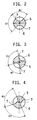
- the flute width ratios are the ratio of the central angles a1, a2 and a3 of the helical flutes 6 shown in Figs. 2-4 to the central angles c1, c2 and c3 of the lands 5. If the heels 7 shown in Figs. 2-4 are chamfered, the chamfered portions are excluded in calculating the flute width ratios.
- a drill having a helical flute formed therein, the helical flute having a constant width and helix angle at the tip portion of the drill, and the helical flute at the remaining portion of the drill having a gradually increasing width and a gradually decreasing helix angle toward the terminal end of the helical flute.
- the helical flute has a helix angle gradually decreasing toward the rear end of the drill, chip flow distance chip is short compared with a conventional drill having a constant helix angle.
- the helical flute in the drill rear portion has also a helix angle, so that chip produced near the drill tip can be pushed out smoothly by screw effects. This also contributes to suppressing increase in the machining power.
- the helical flute has a constant width and helix angle, so that the shape of the tip of the drill will never change even after the drill has been repeatedly reground, so that its performance will not change, either.
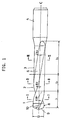
- Fig. 1 shows a drill embodying this invention.
- Figs. 2-4 show sections taken along lines I-I, II-II and III-III of Fig. 1, respectively.
- the illustrated drill has a shank 4 integrally formed at its rear end.
- the letter C indicates the central axis of the drill.
- the drill has a helical flute 6 having a constant width and a helix angle ⁇ 1 in a tip portion 1 of the drill near its tip.
- the flute 6 In a middle portion 2 of the drill, the flute 6 has a width that gradually increases toward the rear end of the drill and a helix angle ⁇ 2 that gradually decreases toward the drill rear end.
- the flute 6 In a rear portion 3 of the drill, the flute 6 has a large, constant width and has a helix angle ⁇ 3 that is smaller than ⁇ 1.
- the drill according to the present invention satisfies the following conditions: ⁇ 1 > ⁇ 3, a1/c1 ⁇ a3/c3, ⁇ 3 ⁇ ⁇ 2 ⁇ ⁇ 1, a1/c1 ⁇ a2/c2 ⁇ a3/c3
- This drill is suited for use in drilling deep holes.
- ⁇ 1 is constant within the range of 15° -30 °
- ⁇ 3 is constant within the range of 3-8 °
- ⁇ 2 is equal to ⁇ 1 at the end near the drill tip and changes gradually until it becomes equal to ⁇ 3 at the rear end.
- the ratios of the width of the flute to the width of the remaining portion in the drill tip portion 1 and that in the drill rear portion 2, i.e. a1 : c1 and a3 : c3, should be constant within the range of 0.5 - 1 : 1 and 0.8 - 1.3 : 1, respectively.
- the length l 1 of the drill tip portion 1 should not be too long to keep sufficiently high chip discharging properties and should not be too short to prevent undue reduction in the number of times the cutting edges can be reground.
- the length l 1 should be preferably equal to or greater than the drill diameter D and equal to or smaller than twice the drill diameter D.
- the length l 2 of the drill middle portion 2 should be long enough to prevent sharp change in the width of the helical flute which is undue to keep high chip discharging properties.
- the length l 2 should preferably be between 1D and 3D.
- the length l 3 of the drill rear portion 3 is determined to a suitable value, taking into consideration the depth of the hole to be drilled.
- Fig. 5 shows a drill of the second embodiment, which has no middle portion 2.
- the helical flute 6 has a gradually increasing width and a gradually decreasing helix angle ⁇ 4 from the point at which the portion 3 connects with the portion 1 to the rear end of the flute 6.
- the flute width ratio and the helix angle in the drill tip portion 1 may be substantially equal to those of the drill of Fig. 1.
- the flute width ratio and helix angle at the terminal end of the helical flute may be substantially equal to those in the drill rear portion of the drill shown in Fig. 1.
- an insert 8 made from cemented carbide and having cutting edges 9 and margins 10 is brazed to the tip of the drill.
- this invention is also applicable to a drill made from a single material or a drill in which margins extend to near the terminal end of the helical flute.
- a cemented carbide insert is to be attached to the tip of the drill, the flute has to be worked before the insert is brazed.
- a ball end mill of the size matching the size of an intended flute is moved longitudinally of the drill from its tip.
- the ball end mill is shifted to one side of the flute while moving it longitudinally.
- the flute is formed by moving the end mill only once. But from the portion of the flute where its width is changing to the flute end, the flute is left unmachined along its other side. Thus, the ball end mill is moved along the flute again to machine the other side.
- a rib is formed on its bottom. Such a rib is removed by buffing or cutting. The helical groove is thus finished.
- Table 1 shows specifications of these drills and test results.
- Chip produced while drilling a hole tends to sharply increase the machining power.
- the drills according to the present invention can discharge chip more efficiently than the conventional drills.
- Specimens 1-3 having helix angles and flute width ratios within the preferred range, were especially high in the ability to discharge chip, as evidenced by the fact that the maximum machining power was equal to or under 4.1 kw.
- Specimens No. 1 to 3 were also high in their ability to drill straight holes. That is, none of the holes drilled by these drills were bent by more than 0.15 mm.
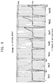
- Fig. 8 shows fluctuations in the machining power for Specimens Nos. 1, 3-5 and 11-13.
- the cutting power fluctuated at a small amplitude, which shows that this drill is low in rigidity.
- the machining power increased sharply when the hole depth increased to about 4D.
- the cutting power did not increase sharply until the hole depth increased to about 5D.
- the drill according to this invention has a helical flute which is wider in the drill rear portion than in the drill tip portion. Its helix angle is smaller in the rear portion than in the tip portion. This drill can form a deep hole while discharging chip smoothly without the possibility of getting clogged with chip.
- the drill Since the width and helix angle of the flute are constant in the drill tip portion, the drill will show unchanged performance after its cutting edges have been regenerated. That is, even after regeneration, the shape of chip will not change at all. This assures a stable drilling.
Applications Claiming Priority (6)
| Application Number | Priority Date | Filing Date | Title |
|---|---|---|---|
| JP26306/96 | 1996-02-14 | ||
| JP2630696 | 1996-02-14 | ||
| JP2630696 | 1996-02-14 | ||
| JP8346828A JPH09277108A (ja) | 1996-02-14 | 1996-12-26 | ドリル |
| JP34682896 | 1996-12-26 | ||
| JP346828/96 | 1996-12-26 |
Publications (2)
| Publication Number | Publication Date |
|---|---|
| EP0790092A1 true EP0790092A1 (fr) | 1997-08-20 |
| EP0790092B1 EP0790092B1 (fr) | 2002-01-23 |
Family
ID=26364072
Family Applications (1)
| Application Number | Title | Priority Date | Filing Date |
|---|---|---|---|
| EP97102359A Expired - Lifetime EP0790092B1 (fr) | 1996-02-14 | 1997-02-13 | Foret |
Country Status (5)
| Country | Link |
|---|---|
| US (1) | US5800101A (fr) |
| EP (1) | EP0790092B1 (fr) |
| JP (1) | JPH09277108A (fr) |
| KR (1) | KR19980063252A (fr) |
| DE (1) | DE69709966T2 (fr) |
Cited By (12)
| Publication number | Priority date | Publication date | Assignee | Title |
|---|---|---|---|---|
| EP0865854A1 (fr) * | 1997-02-22 | 1998-09-23 | HILTI Aktiengesellschaft | Outil de forage et ou de frappe |
| EP0890403A1 (fr) * | 1997-05-15 | 1999-01-13 | Rouiller, Jean-Claude | Foret avec goujures constituées de parties en hélice et de parties rectilignes |
| DE19841978A1 (de) * | 1998-09-14 | 2000-03-23 | Heller Dinklage Gmbh Geb | Bohrer |
| WO2001066899A3 (fr) * | 2000-03-09 | 2001-12-06 | Hawera Probst Gmbh | Outil de forage de roche |
| EP1184115A1 (fr) * | 2000-09-04 | 2002-03-06 | HILTI Aktiengesellschaft | Foret à roche |
| EP1197630A1 (fr) * | 2000-10-11 | 2002-04-17 | HILTI Aktiengesellschaft | Foret pour maçonnerie |
| EP1260296A1 (fr) * | 2001-05-15 | 2002-11-27 | Plica Werkzeugfabrik Ag | Foret |
| WO2004098822A1 (fr) * | 2003-05-09 | 2004-11-18 | Gühring, Jörg | Outil d'alesage pour l'enlevement de copeaux dans des materiaux de moulage |
| US7258180B2 (en) | 2003-11-03 | 2007-08-21 | Illinois Tool Works Inc. | Rotary hammerdrill bit |
| CN102806375A (zh) * | 2011-06-03 | 2012-12-05 | 钴碳化钨硬质合金公司 | 具有涂覆切削刃尖和冷却剂孔的改进型旋转切削刀具及制造方法 |
| US10518336B2 (en) | 2014-11-21 | 2019-12-31 | Kyocera Corporation | Drill and method of manufacturing machined product using the same |
| EP4342610A1 (fr) * | 2022-09-23 | 2024-03-27 | CERATIZIT Hard Material Solutions S.à r.l. | Tête de perçage pour maçonnerie |
Families Citing this family (39)
| Publication number | Priority date | Publication date | Assignee | Title |
|---|---|---|---|---|
| SE509207C2 (sv) | 1995-05-04 | 1998-12-14 | Seco Tools Ab | Verktyg för skärande bearbetning |
| SE512187C2 (sv) * | 1997-04-30 | 2000-02-07 | Seco Tools Ab | Borr |
| JP3851804B2 (ja) * | 2001-10-26 | 2006-11-29 | 住友電工ハードメタル株式会社 | 刃先交換式ツイストドリル |
| US20030185640A1 (en) * | 2002-03-27 | 2003-10-02 | Eiji Ito | Multiple rake drill bits |
| US6652203B1 (en) | 2002-08-30 | 2003-11-25 | Credo Technology Corporation | Precision drill bits |
| US7306411B2 (en) | 2002-09-03 | 2007-12-11 | Mitsubishi Materials Corporation | Drill with groove width variation along the drill and double margin with a thinning section at the tip |
| ATE477870T1 (de) * | 2003-06-04 | 2010-09-15 | Seco Tools Ab | Verfahren und vorrichtung zur herstellung eines zuschnitts für ein werkzeug |
| SE526650C2 (sv) * | 2003-06-04 | 2005-10-18 | Seco Tools Ab | Verktyg |
| DE10333340A1 (de) * | 2003-07-23 | 2005-02-17 | Kennametal Inc. | Bohrer |
| US7101125B2 (en) * | 2003-12-17 | 2006-09-05 | Kennametal Inc. | Twist drill |
| US20080267726A1 (en) * | 2005-07-20 | 2008-10-30 | Norihiro Masuda | Drill |
| US7717654B2 (en) * | 2006-05-26 | 2010-05-18 | Cirino Thomas J | Drill tip with serrated and dowel pinned shank interface |
| US20070274794A1 (en) * | 2006-05-26 | 2007-11-29 | Cirino Thomas J | Oblique angle serration location and drive interface |
| DE102006032005B4 (de) * | 2006-07-10 | 2017-06-08 | EMUGE-Werk Richard Glimpel GmbH & Co. KG Fabrik für Präzisionswerkzeuge | Werkzeug mit sich veränderndem Nutdrallwinkel |
| SE532360C2 (sv) * | 2006-12-06 | 2009-12-22 | Irwin Ind Tool Co | Borrskär |
| WO2008136123A1 (fr) * | 2007-04-26 | 2008-11-13 | Osg Corporation | Taraud hélicoïdal |
| CN101879622B (zh) * | 2007-07-12 | 2012-08-22 | 本田技研工业株式会社 | 钻头 |
| DE102007042280A1 (de) | 2007-09-06 | 2009-03-12 | Komet Group Holding Gmbh | Bohrwerkzeug für Werkzeugmaschinen sowie Verfahren zu dessen Herstellung |
| US8070398B2 (en) * | 2008-02-19 | 2011-12-06 | Irwin Industrial Tool Company | Multi-blade self feed bit |
| WO2009122937A1 (fr) * | 2008-03-31 | 2009-10-08 | 住友電工ハ-ドメタル株式会社 | Fraise deux tailles |
| US7861807B2 (en) * | 2008-12-03 | 2011-01-04 | Black & Decker Inc. | Drill bit including one piece cutting head |
| US20100211113A1 (en) * | 2009-02-17 | 2010-08-19 | Jon Olson | Bone Screw With Channels |
| EP2298491B1 (fr) * | 2009-09-22 | 2017-06-28 | Firma Gühring oHG | Outil doté de canaux pour fluide de refroidissement |
| US20110085862A1 (en) * | 2009-10-10 | 2011-04-14 | William Allen Shaffer | End mill grooved chip breaker flute |
| GB201007032D0 (en) * | 2010-04-27 | 2010-06-09 | Dormer Tools Ltd | Twist drill for advanced materials |
| US20120020751A1 (en) * | 2010-07-23 | 2012-01-26 | Suneel Bhaskar Bhat | Multi-directionally fluted rotary cutting tool |
| EP2672902B1 (fr) * | 2011-02-11 | 2015-11-25 | CPL Holdings Pty Ltd | Trépan |
| US8882412B2 (en) * | 2011-05-11 | 2014-11-11 | Kennametal Inc. | Rotary cutting tool having PCD cutting tip |
| CN102303151A (zh) * | 2011-07-28 | 2012-01-04 | 锑玛(苏州)精密工具有限公司 | 一种强力钻头 |
| CN103252520B (zh) * | 2012-02-20 | 2015-04-01 | 上海工程技术大学 | 一种直槽平底涂层盲孔单槽钻头 |
| WO2014175396A1 (fr) * | 2013-04-26 | 2014-10-30 | 京セラ株式会社 | Foret et procédé permettant de fabriquer un produit coupé à l'aide de ce dernier |
| DE202014103192U1 (de) * | 2014-06-02 | 2014-07-23 | Mikron Tool Sa Agno | Bohrwerkzeug |
| US10052700B2 (en) * | 2015-07-28 | 2018-08-21 | Kennametal Inc. | Rotary cutting tool with blades having repeating, unequal indexing and helix angles |
| JP6725684B2 (ja) * | 2016-11-15 | 2020-07-22 | 京セラ株式会社 | 回転工具及びそれを用いた切削加工物の製造方法 |
| US11679442B2 (en) | 2018-06-22 | 2023-06-20 | Maestro Logistics, Llc | Drill bit and method for making a drill bit |
| EP3666433B1 (fr) * | 2018-12-13 | 2023-09-27 | CERATIZIT Balzheim GmbH & Co. KG | Outil de perçage |
| CN112077370A (zh) | 2019-06-13 | 2020-12-15 | 肯纳金属印度有限公司 | 可转位钻头刀片 |
| CN110744108B (zh) * | 2019-10-15 | 2020-08-14 | 大连理工大学 | 一种加工复合材料具有刃倾槽结构的钻头加工方法 |
| US11948700B2 (en) | 2020-11-11 | 2024-04-02 | Grant Charters | In-situ method of drilling to collect dry samples from a nuclear reactor core interior for analysis |
Citations (7)
| Publication number | Priority date | Publication date | Assignee | Title |
|---|---|---|---|---|
| FR1302191A (fr) * | 1961-09-29 | 1962-08-24 | Stalker Drill Works Ltd | Foret |
| DE3545586A1 (de) * | 1985-12-21 | 1987-07-02 | Komet Stahlhalter Werkzeug | Bohrwerkzeug |
| JPS62213911A (ja) * | 1986-03-14 | 1987-09-19 | Mitsubishi Metal Corp | 穴明け工具 |
| EP0126409B1 (fr) * | 1983-05-18 | 1987-09-23 | Hawera Probst GmbH + Co. | Outil de forage |
| CH665979A5 (en) * | 1986-03-27 | 1988-06-30 | Precitool S A | Twist drill bit - has shank grooves at angle which increases progressively towards tip from 15 to 40 degrees |
| JPH03142116A (ja) * | 1989-10-27 | 1991-06-17 | Mitsubishi Materials Corp | 穴明け工具 |
| EP0642863A1 (fr) * | 1993-09-14 | 1995-03-15 | Seco Tools Ab | Foret |
Family Cites Families (4)
| Publication number | Priority date | Publication date | Assignee | Title |
|---|---|---|---|---|
| US750537A (en) * | 1904-01-26 | Drilling-tool | ||
| SE502255C2 (sv) * | 1991-12-16 | 1995-09-25 | Sandvik Ab | Borr med spånkanaler, innefattande en första och en andra spånmatande zon, med olika tvärsnitt |
| US5350261A (en) * | 1992-03-12 | 1994-09-27 | Mitsubishi Materials Corporation | Twist drill |
| US5704740A (en) * | 1995-06-26 | 1998-01-06 | Walter Ag | Drilling tool, particularly for metallic materials |
-
1996
- 1996-12-26 JP JP8346828A patent/JPH09277108A/ja active Pending
-
1997
- 1997-02-12 US US08/798,920 patent/US5800101A/en not_active Expired - Lifetime
- 1997-02-13 DE DE69709966T patent/DE69709966T2/de not_active Expired - Lifetime
- 1997-02-13 EP EP97102359A patent/EP0790092B1/fr not_active Expired - Lifetime
- 1997-02-13 KR KR1019970004200A patent/KR19980063252A/ko not_active Application Discontinuation
Patent Citations (7)
| Publication number | Priority date | Publication date | Assignee | Title |
|---|---|---|---|---|
| FR1302191A (fr) * | 1961-09-29 | 1962-08-24 | Stalker Drill Works Ltd | Foret |
| EP0126409B1 (fr) * | 1983-05-18 | 1987-09-23 | Hawera Probst GmbH + Co. | Outil de forage |
| DE3545586A1 (de) * | 1985-12-21 | 1987-07-02 | Komet Stahlhalter Werkzeug | Bohrwerkzeug |
| JPS62213911A (ja) * | 1986-03-14 | 1987-09-19 | Mitsubishi Metal Corp | 穴明け工具 |
| CH665979A5 (en) * | 1986-03-27 | 1988-06-30 | Precitool S A | Twist drill bit - has shank grooves at angle which increases progressively towards tip from 15 to 40 degrees |
| JPH03142116A (ja) * | 1989-10-27 | 1991-06-17 | Mitsubishi Materials Corp | 穴明け工具 |
| EP0642863A1 (fr) * | 1993-09-14 | 1995-03-15 | Seco Tools Ab | Foret |
Non-Patent Citations (2)
| Title |
|---|
| PATENT ABSTRACTS OF JAPAN vol. 012, no. 067 (M - 673) 2 March 1988 (1988-03-02) * |
| PATENT ABSTRACTS OF JAPAN vol. 015, no. 362 (M - 1157) 12 September 1991 (1991-09-12) * |
Cited By (18)
| Publication number | Priority date | Publication date | Assignee | Title |
|---|---|---|---|---|
| EP0865854A1 (fr) * | 1997-02-22 | 1998-09-23 | HILTI Aktiengesellschaft | Outil de forage et ou de frappe |
| EP0890403A1 (fr) * | 1997-05-15 | 1999-01-13 | Rouiller, Jean-Claude | Foret avec goujures constituées de parties en hélice et de parties rectilignes |
| DE19841978A1 (de) * | 1998-09-14 | 2000-03-23 | Heller Dinklage Gmbh Geb | Bohrer |
| DE19841978C2 (de) * | 1998-09-14 | 2000-11-23 | Heller Dinklage Gmbh Geb | Bohrer |
| WO2001066899A3 (fr) * | 2000-03-09 | 2001-12-06 | Hawera Probst Gmbh | Outil de forage de roche |
| US6742610B2 (en) | 2000-03-09 | 2004-06-01 | Hawera Probst Gmbh | Rock drill |
| EP1184115A1 (fr) * | 2000-09-04 | 2002-03-06 | HILTI Aktiengesellschaft | Foret à roche |
| US6675917B2 (en) | 2000-10-11 | 2004-01-13 | Hilti Aktiengesellschaft | Twist drill bit for rock drilling |
| EP1197630A1 (fr) * | 2000-10-11 | 2002-04-17 | HILTI Aktiengesellschaft | Foret pour maçonnerie |
| EP1260296A1 (fr) * | 2001-05-15 | 2002-11-27 | Plica Werkzeugfabrik Ag | Foret |
| WO2004098822A1 (fr) * | 2003-05-09 | 2004-11-18 | Gühring, Jörg | Outil d'alesage pour l'enlevement de copeaux dans des materiaux de moulage |
| US7296954B2 (en) | 2003-05-09 | 2007-11-20 | Joerg Guehring | Drilling tool for cutting cast materials |
| US7258180B2 (en) | 2003-11-03 | 2007-08-21 | Illinois Tool Works Inc. | Rotary hammerdrill bit |
| CN102806375A (zh) * | 2011-06-03 | 2012-12-05 | 钴碳化钨硬质合金公司 | 具有涂覆切削刃尖和冷却剂孔的改进型旋转切削刀具及制造方法 |
| US10518336B2 (en) | 2014-11-21 | 2019-12-31 | Kyocera Corporation | Drill and method of manufacturing machined product using the same |
| DE112015005260B4 (de) | 2014-11-21 | 2023-09-28 | Kyocera Corporation | Bohrer und Verfahren zum Herstellen eines bearbeiteten Produkts unter Verwendung desselben |
| EP4342610A1 (fr) * | 2022-09-23 | 2024-03-27 | CERATIZIT Hard Material Solutions S.à r.l. | Tête de perçage pour maçonnerie |
| WO2024061734A1 (fr) * | 2022-09-23 | 2024-03-28 | Ceratizit Hard Material Solutions S.À R.L. | Tête de perçage pour maçonnerie |
Also Published As
| Publication number | Publication date |
|---|---|
| US5800101A (en) | 1998-09-01 |
| KR19980063252A (ko) | 1998-10-07 |
| JPH09277108A (ja) | 1997-10-28 |
| DE69709966T2 (de) | 2002-10-02 |
| EP0790092B1 (fr) | 2002-01-23 |
| DE69709966D1 (de) | 2002-03-14 |
Similar Documents
| Publication | Publication Date | Title |
|---|---|---|
| EP0790092B1 (fr) | Foret | |
| KR100838767B1 (ko) | 트위스트 드릴 | |
| AU2005249662B2 (en) | Drill, particularly a spiral drill | |
| US5486075A (en) | Boring tool | |
| EP0642863B1 (fr) | Foret | |
| US6929434B2 (en) | Rotary cutting tool | |
| EP0876868A1 (fr) | Foret | |
| WO1988001214A1 (fr) | Foret a auto-centrage avec pointe pilote | |
| US20040042859A1 (en) | Drill with improved cutting insert formation | |
| KR20040039373A (ko) | 드릴용 커팅포인트 | |
| KR20020017908A (ko) | 구멍뚫기공구 | |
| US6749375B2 (en) | End milling cutter for machining workpieces made of a non-ferrous metal or plastic | |
| US5993119A (en) | Drill having cooling channel and chip flutes | |
| US8043032B2 (en) | Interchangeable tool part for a reamer | |
| US6283682B1 (en) | Helically fluted twist drill device | |
| US5967707A (en) | Short-hole drill bit | |
| JPH0258042B2 (fr) | ||
| JPS6312891Y2 (fr) | ||
| JPH05261612A (ja) | ドリル | |
| CN218964134U (zh) | 深孔加工钻 | |
| CN220407201U (zh) | 钻铰刀 | |
| KR200211512Y1 (ko) | 복합 가공용 리머 | |
| JPH0560715U (ja) | 超硬ドリル | |
| JP2003094220A (ja) | 穴明け工具 | |
| JPH03117508A (ja) | ドリル |
Legal Events
| Date | Code | Title | Description |
|---|---|---|---|
| PUAI | Public reference made under article 153(3) epc to a published international application that has entered the european phase |
Free format text: ORIGINAL CODE: 0009012 |
|
| AK | Designated contracting states |
Kind code of ref document: A1 Designated state(s): DE FR GB IT |
|
| 17P | Request for examination filed |
Effective date: 19970731 |
|
| 17Q | First examination report despatched |
Effective date: 19971114 |
|
| GRAG | Despatch of communication of intention to grant |
Free format text: ORIGINAL CODE: EPIDOS AGRA |
|
| GRAG | Despatch of communication of intention to grant |
Free format text: ORIGINAL CODE: EPIDOS AGRA |
|
| GRAH | Despatch of communication of intention to grant a patent |
Free format text: ORIGINAL CODE: EPIDOS IGRA |
|
| GRAH | Despatch of communication of intention to grant a patent |
Free format text: ORIGINAL CODE: EPIDOS IGRA |
|
| GRAA | (expected) grant |
Free format text: ORIGINAL CODE: 0009210 |
|
| REG | Reference to a national code |
Ref country code: GB Ref legal event code: IF02 |
|
| AK | Designated contracting states |
Kind code of ref document: B1 Designated state(s): DE FR GB IT |
|
| PG25 | Lapsed in a contracting state [announced via postgrant information from national office to epo] |
Ref country code: IT Free format text: LAPSE BECAUSE OF FAILURE TO SUBMIT A TRANSLATION OF THE DESCRIPTION OR TO PAY THE FEE WITHIN THE PRE;WARNING: LAPSES OF ITALIAN PATENTS WITH EFFECTIVE DATE BEFORE 2007 MAY HAVE OCCURRED AT ANY TIME BEFORE 2007. THE CORRECT EFFECTIVE DATE MAY BE DIFFERENT FROM THE ONE RECORDED.SCRIBED TIME-LIMIT Effective date: 20020123 |
|
| REF | Corresponds to: |
Ref document number: 69709966 Country of ref document: DE Date of ref document: 20020314 |
|
| ET | Fr: translation filed | ||
| PLBE | No opposition filed within time limit |
Free format text: ORIGINAL CODE: 0009261 |
|
| STAA | Information on the status of an ep patent application or granted ep patent |
Free format text: STATUS: NO OPPOSITION FILED WITHIN TIME LIMIT |
|
| 26N | No opposition filed | ||
| PGFP | Annual fee paid to national office [announced via postgrant information from national office to epo] |
Ref country code: FR Payment date: 20030210 Year of fee payment: 7 |
|
| PGFP | Annual fee paid to national office [announced via postgrant information from national office to epo] |
Ref country code: GB Payment date: 20030212 Year of fee payment: 7 |
|
| PG25 | Lapsed in a contracting state [announced via postgrant information from national office to epo] |
Ref country code: GB Free format text: LAPSE BECAUSE OF NON-PAYMENT OF DUE FEES Effective date: 20040213 |
|
| GBPC | Gb: european patent ceased through non-payment of renewal fee |
Effective date: 20040213 |
|
| PG25 | Lapsed in a contracting state [announced via postgrant information from national office to epo] |
Ref country code: FR Free format text: LAPSE BECAUSE OF NON-PAYMENT OF DUE FEES Effective date: 20041029 |
|
| REG | Reference to a national code |
Ref country code: FR Ref legal event code: ST |
|
| PGFP | Annual fee paid to national office [announced via postgrant information from national office to epo] |
Ref country code: DE Payment date: 20160209 Year of fee payment: 20 |
|
| REG | Reference to a national code |
Ref country code: DE Ref legal event code: R071 Ref document number: 69709966 Country of ref document: DE |