EP0789981B1 - Optimierung eines thermischen reaktors - Google Patents
Optimierung eines thermischen reaktors Download PDFInfo
- Publication number
- EP0789981B1 EP0789981B1 EP95937441A EP95937441A EP0789981B1 EP 0789981 B1 EP0789981 B1 EP 0789981B1 EP 95937441 A EP95937441 A EP 95937441A EP 95937441 A EP95937441 A EP 95937441A EP 0789981 B1 EP0789981 B1 EP 0789981B1
- Authority
- EP
- European Patent Office
- Prior art keywords
- reactor
- thermal
- model
- load
- online
- Prior art date
- Legal status (The legal status is an assumption and is not a legal conclusion. Google has not performed a legal analysis and makes no representation as to the accuracy of the status listed.)
- Expired - Lifetime
Links
Images


Classifications
-
- H—ELECTRICITY
- H10—SEMICONDUCTOR DEVICES; ELECTRIC SOLID-STATE DEVICES NOT OTHERWISE PROVIDED FOR
- H10P—GENERIC PROCESSES OR APPARATUS FOR THE MANUFACTURE OR TREATMENT OF DEVICES COVERED BY CLASS H10
- H10P72/00—Handling or holding of wafers, substrates or devices during manufacture or treatment thereof
- H10P72/06—Apparatus for monitoring, sorting, marking, testing or measuring
- H10P72/0602—Temperature monitoring
-
- C—CHEMISTRY; METALLURGY
- C23—COATING METALLIC MATERIAL; COATING MATERIAL WITH METALLIC MATERIAL; CHEMICAL SURFACE TREATMENT; DIFFUSION TREATMENT OF METALLIC MATERIAL; COATING BY VACUUM EVAPORATION, BY SPUTTERING, BY ION IMPLANTATION OR BY CHEMICAL VAPOUR DEPOSITION, IN GENERAL; INHIBITING CORROSION OF METALLIC MATERIAL OR INCRUSTATION IN GENERAL
- C23C—COATING METALLIC MATERIAL; COATING MATERIAL WITH METALLIC MATERIAL; SURFACE TREATMENT OF METALLIC MATERIAL BY DIFFUSION INTO THE SURFACE, BY CHEMICAL CONVERSION OR SUBSTITUTION; COATING BY VACUUM EVAPORATION, BY SPUTTERING, BY ION IMPLANTATION OR BY CHEMICAL VAPOUR DEPOSITION, IN GENERAL
- C23C16/00—Chemical coating by decomposition of gaseous compounds, without leaving reaction products of surface material in the coating, i.e. chemical vapour deposition [CVD] processes
- C23C16/44—Chemical coating by decomposition of gaseous compounds, without leaving reaction products of surface material in the coating, i.e. chemical vapour deposition [CVD] processes characterised by the method of coating
- C23C16/52—Controlling or regulating the coating process
Definitions
- the present invention pertains to the field of thermal processes. More particularly, this invention relates to the optimization of thermal reactor or diffusion furnace performance for thermally activated processes.
- Thermally activated processes typically require highly uniform thermal processing control to achieve maximum efficiency.
- integrated circuit chips typically comprise a set of layered structures formed on a silicon substrate via thermally activated processes.
- the layered structures usually include, for example, polysilicon structures, oxide structures, and diffusion regions.
- such structures are formed on a silicon wafer substrate in a controlled thermal reactive environment suitable for forming the required structures on the silicon wafers.
- thermal reactors are also referred to as diffusion furnaces.
- a typical prior thermal reactor includes a quartz jar that contains a set of silicon wafers.
- Such a thermal reactor usually includes a set of heating elements that surround the quartz jar. The heating elements in such a thermal reactor usually subdivide the thermal reactor into a set of thermal zones. The heating elements for the thermal zones are usually separately controllable.
- Prior thermal reactor systems usually include a reactor controller that controls the heating elements of the thermal reactor as well as the pressure and flow rates of reactive gasses in the thermal reactor.
- the deposition rate of polysilicon structures and oxide structures and the rate of growth of diffusion regions on the silicon wafers are related to the wafer temperature.
- prior reactor controllers usually attempt to achieve the desired end of run physical parameters for the structures formed on the silicon wafers by monitoring and adjusting the temperature and gas flows of the thermal reactor during deposition.
- Such prior reactor controllers typically monitor the temperature of the thermal reactor via online temperature measurements.
- online temperature measurements are obtained with thermocouples positioned within or near the quartz jar and with thermocouples inserted through the heating elements of the thermal reactor.
- a furnace temperature control apparatus is known from US-A-5 099 442.
- PID reactor controllers typically employ proportional integral derivative (PID) methods to control the temperature of the silicon wafers.
- PID reactor controllers usually obtain temperature measurements from the thermocouples in the thermal reactor as an indication of the temperature of the silicon wafers in the quartz jar.
- PID reactor controllers adjust heater power control signals to the thermal reactor to maintain a set point temperature according to a predetermined process control recipe.
- thermocouple measurements provide a reasonable indication of silicon wafer temperatures only after a long stabilization period in the thermal reactor.
- a long thermal reactor stabilization period typically increases the total cycle time for forming structures on the silicon wafers load. Such increased cycle time usually increases the cost of manufacturing integrated circuit chips.
- a protracted thermal reactor stabilization period becomes an increasingly larger portion of total cycle time as wafer processes evolve that require shorter intervals for formation of structures.
- a protracted thermal reactor stabilization period becomes a larger portion of total cycle time as the thermal mass in the thermal reactor increases.
- Such increased stabilization period also results in unwanted diffusion of dopants creating difficulty in making sub-micron devices.
- prior PID reactor controllers cannot accurately control the thermal gradients that occur along the major axis of the thermal reactor.
- silicon wafers located at different positions along the axis of the thermal reactor are exposed to differing temperatures during thermal processing.
- prior PID reactor controllers cannot accurately control the thermal gradients that occur radially on the silicon wafers.
- integrated circuit chips located at differing radial positions on a given silicon wafer are exposed to differing temperatures during thermal processing.
- One object of the present invention is to improve the utility of thermal reactors used in thermally activated processes.
- Another object of the present invention is to optimize thermal reactor performance for thermally activated processes employed in semiconductor manufacture.
- Another object of the present invention is to decrease the total cycle time for forming structures on integrated circuit chips in a thermal reactor.
- Another object of the present invention is to decrease the cost of manufacturing integrated circuit chips.
- a further object of the present invention is to provide an accurate indication of wafer load temperatures in a thermal reactor.
- Another object of the present invention is to exploit thermal gradients that occur in a thermal reactor to reduce end of run physical parameter variations in integrated circuit chips.
- Another object of the present invention is to accurately characterize the thermal behavior of a thermal reactor.
- a further object of the present invention is to develop an online model of thermal reactor behavior and to employ online multi-variable control of the thermal reactor.
- Another object of the present invention is to optimize thermal reactor performance for flat-panel display manufacture and photovoltarc manufacture.
- thermo reactor system comprising:
- FIG. 1 illustrates a thermal reactor system for one embodiment that includes a thermal reactor 10 and a reactor control system 50.
- the thermal reactor 10 contains one or two quartz jars 14 that houses a wafer load 12.
- the wafer load 12 comprises a set of silicon wafers supported by a quartz structure and distributed along the major axis of the thermal reactor 10 within the quartz jar 14.
- the thermal reactor 10 also contains a set of heating elements 20.
- a set of profile thermocouples 16 are shown next to an interior wall of the quartz jar 14.
- the profile thermocouples 16 are between the two walls of the quartz jar 14.
- the profile thermocouples 16 are next to the wafer load.
- the heating elements 20 comprise a set of 5 separately controllable heating elements that subdivide thermal reactor 10 into a set of heater zones 1 - 5.
- the temperature of each heater zone 1 - 5 is sensed by a set of corresponding spike thermocouples 21 - 25.
- the profile thermocouples 16 comprises a set of thermocouples that sense profile temperatures for each of the heater zones 1 - 5.
- the reactor control system 50 comprises an online model 30 and a multi-variable controller 32.
- the online model 30 obtains measurements from the spike thermocouples 21 - 25 and the profile thermocouples 16 from the thermal reactor 10. The measurements from the spike thermocouples 21 - 25 and the profile thermocouples 16 are referred to as T thermocouple .
- the online model 30 also obtains measurements of the thermal reactor input power P input to the thermal reactor 10.
- the online model 30 implements a thermal model of the thermal reactor 10.
- the thermal model of the online model 30 generates estimated wafer temperatures T model from the thermal reactor power input P input and the spike and profile thermocouple measurements T thermocouple .
- the multi-variable controller 32 generates the thermal reactor input power P input from the estimated wafer temperatures T model and a recipe set point or time-varying trajectory T control .
- the multi-variable controller 32 implements a set of transfer functions that use the recipe set point or time-varying trajectory T control and the estimated wafer temperatures T model to generate the thermal reactor input power P input to minimize the end of run physical parameters for the structures formed on the wafer load 12.
- Figure 2 illustrates a process for designing the reactor control system 50 for one embodiment.
- the online model 30 is generated by initially determining a thermal dynamic model of the thermal reactor 10 during process steps 100-108.
- a set of reactor power test signals are created for characterizing the thermal behavior of the thermal reactor 10.
- the reactor power test signals are referred to as P test .
- the reactor power test signals P test are designed to exercise the high and the low bandwidth thermal dynamics of the thermal reactor 10 and the wafer load 12.
- the reactor power test signals P test are created to provide sufficient excitation and richness to uncover the thermal behavior of the thermal reactor 10 for timescales from 20-30 seconds up to several hours.
- the reactor power test signals P test are applied to the thermal reactor 10 while the response of the thermal reactor 10 and the response of the wafer load 12 are synchronously captured.
- the test signals P test consist of pseudo-random binary sequence, simultaneously in each heater zone of the thermal reactor 10, such that the heater power changes no faster than every five minutes and the wafer temperature changes no more than 15 degrees from the nominal.
- the test signal keeps the wafer temperature around the nominal for three hours.
- the test signals P test consists of step inputs of 15 degrees lasting 10 minutes to a cascade profile PID controller 61 dwelling around the nominal value for three hours as shown in Figure 3b .
- FIG. 3a is a diagram that illustrates process step 102 for one embodiment.
- the reactor power test signals P test are generated by a reactor test signal generator 60.
- the quartz jar 14 is filled with an inert gas such as nitrogen or argon to provide a nonreactive environment for the wafer load 12.
- wafer thermocouples (not shown) are placed on the wafer load 12 and are distributed through each of the heater zones 1 - 5.
- a reactor response data acquisition unit 62 obtains measurements T thermocouple from the spike thermocouples 21 - 25 and the profile thermocouples 16 of the thermal reactor 10. In addition, the reactor response data acquisition unit 62 obtains measurements T wafer from the wafer thermocouples. The reactor response data acquisition unit 62 captures the measurements T thermocouple and T wafer synchronously as the reactor test signal . generator 60 generates the reactor power test signals P test .
- the measurements of the reactor response data acquisition unit 62 are synchronous in time with a sample rate of between 1 and 5 seconds for one embodiment.
- the sample rate is sufficient to capture the thermal dynamic behavior of the thermal reactor 10 and the wafer load 12 for the timescales of interest.
- the reactor power test signals P test control the heating elements of each heater zones 1 - 5.
- the reactor power test signals P test also control the flow rates and pressure of the inert gas inside the quartz jar 14.
- a reactor model for the thermal reactor 10 is determined from the thermal reactor response indicated T thermocouple and the wafer load response indicated T wafer captured at process step 102.
- the reactor model is determined in a manner to reflect the high bandwidth thermodynamics of the wafer load 12 as well as the lower bandwidth thermal drift of the thermal reactor 10 and the wafer load 12.
- the reactor model is determined by initially computing a set of high order auto regressive with exogenous inputs (ARX) model parameters at differing temperatures T nominal,i .
- the differing temperatures T nominal,i .of the high order ARX model comprise 400, 500, 600 ... through 1100° C.
- y t comprises the five profile thermocouple signals, the five spike thermocouple signals and ten wafer thermocouple signals.
- the ten wafer thermocouple signals correspond to five instrumented Silicon wafers located at the same axial positions in the thermal reactor 10 as the profile thermocouples in the 200 mm diameter wafer load 12.
- Each instrumented wafer of the wafer load 12 has one thermocouple at the center and one thermocouple 6 mm away from the edge of the wafer.
- the signals are expressed as perturbations in degrees C from corresponding steady-state values y bias .
- u t is a vector of inputs at time t dimensioned m x 1 .
- u t comprises the perturbations of five heater inputs around corresponding steady-state values u bias at time t .
- ⁇ t is vector of independent white noise at time t dimensioned p x 1 .
- the matrices are dimensioned as AAj:p x p, and BBj:p x m .
- the number of lags n is eight.
- the coefficients of the ARX model are computed using least-squares parameter estimation procedure.
- the preferred embodiments use significance of reduction in estimation error in wafer temperatures.
- This estimation of wafer temperature uses a Kalman filter for prediction of wafer temperatures from only the heater powers, profile and spike thermocouple signals. Using the F-ratio test on the ARX residual errors leads to poor on-line prediction of wafer temperatures.
- n 8
- p 20
- m 5
- n t the dimension of state vector x t is 160.
- the covariance R ⁇ of ⁇ t is estimated from the actual residual error sequence obtained during parameter estimation.
- the disturbance model is embedded in these matrices and the innovations covariance R ⁇ .
- the vector s t corresponds to the measured temperatures and is of dimension p1x1
- the vector w t corresponds to the unmeasured temperatures and is of dimension p2x1 .
- the output matrix C and the bias vector y bias are partitioned as where the matrix C s is of dimension p 1 x n t and the matrix C w is of dimension p 2 x n t .
- the high order model ARX model parameters are determined in order to accurately characterize the high bandwidth thermal dynamics of the thermal reactor 10. Accordingly, the high order ARX model is chosen having orders of over one hundred and provides over one hundred time lagged variables that indicate the thermal behavior of the thermal reactor 10. In addition, the high order ARX model parameters are determined to retain noise and disturbance thermal dynamics of the thermal reactor 10. The high orders of the ARX model parameters at the differing temperatures ensures that the slow dynamic drift in the heating of the quartz jar 14 and the slow dynamics of the heating elements 20 as well as the slow dynamics of the heating of the wafer load 12 are accurately reflected in the reactor model. In addition, the high orders of the ARX model parameters enable the reactor model to accurately reflect the faster thermal dynamics that occur within the wafer load 12.
- the initially computed set of high order ARX model parameters at each temperature T nominal,i is then reduced from over hundred states down to tens of states.
- Such model reduction results in increased efficiency of computation in subsequent steps of the design process.
- such model reduction eliminates numerical illconditioning arising from poorly observable and controllable states.
- Balanced Model Reduction techniques are used for obtaining reduced order models.
- An alternative is to use Schur method based model reduction techniques. For model reduction only the input output behavior is considered.
- the reduced order ARX model parameters at each temperature T nominal,i are obtained in state-space form including matrices A i , B i , C w,i and C s,i , that describe the time evolution of the internal states x i , which consists of the time lagged variables that indicate the thermal behavior of the thermal reactor 10.
- Each set of such reduced order ARX parameters gives a sub-model MOD i that accurately describe thermal behavior of the thermal reactor 10 in a temperature range T range,i .
- the temperature ranges are 350-450, 450-550, ... through 1050-1150°C.
- a reactor model is obtained by switching the sub-models MOD i in their respective range of validity to obtain a single output vector y t ⁇
- Conventional gain-scheduling requires identical internal representations x i at each operating temperature T nominal,i .
- high order or reduced order ARX models do not have a unique internal representation requiring on-line computation of initial conditions at the time of switching.
- each model MOD i implements a fast tracking function that tracks the thermal behavior of the currently valid model outside its valid temperature range T range,i .
- the fast tracking function of the models prevents the occurrence of a large transient as the temperature of the thermal reactor transitions between the valid ranges of the models.
- x i,t+1 A i x i,t + B i u t + K i ( y t - C i x i,t ) ⁇ switch,i
- the switch parameter ⁇ switch,i is zero when MOD i is in its valid temperature T range,i and one otherwise.
- the gain matrix K i is obtained by pole placement to ensure fast tracking.
- an online reactor model is determined from the reduced order ARX model calculated at process step 104.
- the online reactor model determined at process step 106 is implemented in the online model 30 of the reactor control system 50 to generate estimates of wafer load 12 temperatures and other internal temperatures.
- FIG 4 is a simplified illustration of the online reactor model.
- the online reactor model includes a set of wafer temperature estimators M Ki .
- estimaters M K1 -M K3 For purposes of illustration consider estimaters M K1 -M K3 .
- Each estimator M K1 -M K3 corresponds to a differing reactor temperature range.
- the estimator M K1 corresponds to the temperature range 500-600° C
- the estimator M K2 corresponds to the temperature range of 600-700° C
- the estimator M K3 corresponds to the temperature range of 700-800° C.
- Each estimator M K1 -M K3 generates an estimated temperature of the wafer load 12 for the corresponding temperature range.
- the estimator M K1 generates the estimated wafer temperature T model1 valid in the temperature range between 500-600° C.
- the estimator M K2 generates the estimated wafer temperature T model2 valid in the temperature range between 600-700° C
- the estimator M K3 generates the estimated wafer temperature T model3 valid in the temperature range between 700-800° C.
- the gain matrices L i are obtained by solving steady-state Riccati equations using the reduced order ARX model parameters as described at process step 104.
- a time varying Kalman filter may be generated.
- time varying Kalman filters are computationally expensive to solve in an online system or would require large amounts of data storage if computed off-line and stored in the reactor control system 50.
- the estimated wafer temperatures are obtained by switching the estimators M Ki in their respective range of validity to obtain T model.
- Conventional gain scheduling requires identical internal representation at each operating point. Reduced order models or high order ARX models do not have a unique internal representation. Switching the entire estimator controller structure or only the estimator without tracking lead to large transients on switching.
- each of the estimators M K1 - M K3 implement a fast tracking function that tracks the estimated wafer temperature generated outside the corresponding valid temperature range.
- the fast tracking functions of the estimators M K1 -M K3 prevent the occurrence of large transients as the temperature of the thermal reactor 10 transitions between the valid ranges of the estimators M K1 -M K3 .
- the estimator M K1 and the estimator M K3 lock onto and track the estimated wafer temperatures T model2 while the temperature of the thermal reactor 10 is within the valid range of the estimator M K2 .
- the estimator M K2 tracks the estimated wafer temperatures generated by the estimator M K1 or the estimator M K3 according to the relationship between the temperature of the thermal reactor 10 and the valid ranges of the estimators M K1 -M K3 .
- the switch parameter ⁇ switch,i is zero when MK i is in its valid temperature T range,i and one otherwise.
- the gain matrix F i is obtained by pole placement to ensure fast tracking.
- Figure 5 illustrates the verification of the online reactor model at process step 108.
- the reactor test signal generator 60 generates input power signals P input to the thermal reactor 10.
- the online model 30 receives the reactor power input control P input from the reactor test signal generator 60.
- the online model 30 also receives the spike and profile thermocouple measurements T thermocouple from the thermal reactor 10.
- the online model 30 generates estimated wafer temperatures T model using the estimators M K1 -M K3 .
- the estimated wafer temperatures T model are compared to the wafer temperature measurements T wafer obtained from the thermal couples mounted on the wafer load 12.
- a multi-variable controller is determined from the online reactor model.
- the multi-variable controller determined at process step 110 is implemented in the multi-variable controller 32 of the reactor control system 50.
- the multi-variable controller employs the interaction of heater powers in the differing heater zones 1 - 5 of the thermal reactor 10 to minimize the time average of wafer temperature deviation from the set point 46 at all locations of the wafer load 12.
- the set point 46 may be a constant set point or a time varying trajectory.
- Process step 110 involves an off-line design procedure for computing a set of multi-variable controller equations given the online model determined at process step 106.
- the controller equations are calculated to minimize the average wafer temperature deviation in the wafer load 12.
- the process step 110 involves solving a set of steady state Ricatti equations for multi-variable control while testing for robustness and transient response.
- the weights of the Ricatti equations are modified to meet the robustness and transient response requirements.
- Alternative embodiment uses frequency weighted H ⁇ controllers and optimal ⁇ controllers
- the process step 110 is accomplished using reduced order ARX models.
- the multi-variable controller 32 determines the appropriate thermal reactor power signals P input given the set point 46 and the estimation of wafer temperatures T model .
- the set point 46 provide a process control recipe for forming structures in the wafer load 12.
- the set points 46 provide a time varying trajectory for optimizing end of run wafer parameters on the wafer load 12.
- a time varying set point trajectory is determined that optimizes end of run physical parameters for structures formed on the wafer load 12.
- the time varying temperature set point trajectory is referred to as T traj (t) .
- Time varying trajectories are determined to exploit the fact that temperature gradients occur within the thermal reactor 10. For example, a temperature gradient occurs along the length of the wafer load 12 along the major axis of the thermal reactor 10. In addition, radial temperature gradients occur on each silicon wafer of the wafer load 12.
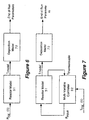
- Figure 6 illustrates the computational models employed at process step 112.
- a deposition model 72 relates the end of run physical wafer parameters such as oxide thickness, poly thickness, and diffusion density to the wafer temperatures on the wafer load 12 during deposition.
- the deviation of end-of-run film thickness ⁇ d ox is given by: i.e., proportional to time average of temperature deviation during deposition or growth.
- the steady-state temperature of growing film in a reactor at various locations can be changed by steady-state temperature deviations are limited in their degrees of freedom to the number of independently actuated heaters.
- the best achievable uniformity is then limited by steady-state design of the reactor geometry and insulation.
- non-steady-state heater powers and non-steady temperatures during growth can be used to remove the limitations of steady-state behavior.
- there is only one heater in a reactor only one dimensional variation in steady-state temperature and the corresponding deposition profile is possible.
- very high dimensional small signal variations in the time averaged temperature at the end of growth or deposition are possible. Practical limitation on the dimensionality and size of such variations comes from bandwidth of allowable time variations in temperature due to inaccurate thermal models, limited heating and cooling authority and thermal stress limits.
- the end of run wafer parameters can be arbitrarily changed within some bounds by changing the reactor power signals P input over time.
- the reactor model and the deposition model 72 are used to compute a time varying set point trajectory T traj (t) that minimizes variation in end of run parameters on the wafer load 12.
- Figure 7 illustrates a closed loop online implementation of a time varying set point trajectory that minimizes end of run wafer parameter variation.
- the multi-variable controller 32 uses spike and profile thermocouple measurements T thermocouple and the time varying reactor temperature trajectory T traj (t) to generate a reactor power signal P input to the thermal reactor 10.
- the reactor power signal P input is also used by the model 30 to generate estimated wafer temperatures T model for the deposition model 72 which indicates end of run parameters.
- the time varying trajectories determined as process step 112 minimize the variation in final oxide thickness, poly thickness, sheet resistance, and junction depth on the wafer load 12.
- the multi-variable control design models implemented in the multi-variable controller 32 fail when the input heater power to the thermal reactor 10 saturates.
- the online model for the thermal reactor 10 is approximated by a pure integrator when the heater power for the thermal reactor 10 saturates.
- the reactor control problem is then solved as a minimum time problem with an estimation of final time in an application of feedback to recompute.
- the time varying trajectory determined at process step 112 is refined.
- the time varying trajectory T traj (t) is refined by correlating the actual end of run parameters of test silicon wafers on the wafer load 12 to the estimated wafer temperatures T model determined from the online model 30.
Landscapes
- Chemical & Material Sciences (AREA)
- General Chemical & Material Sciences (AREA)
- Chemical Kinetics & Catalysis (AREA)
- Engineering & Computer Science (AREA)
- Materials Engineering (AREA)
- Mechanical Engineering (AREA)
- Metallurgy (AREA)
- Organic Chemistry (AREA)
- Feedback Control In General (AREA)
Claims (19)
- Verfahren zum Steuern eines thermischen Heißwandreaktors (10), die Schritte umfassend:Bestimmen eines Reaktormodells, das ein thermisches Verhalten des thermischen Reaktors anzeigt und ein thermisches Verhalten einer Last (12), die in dem thermischen Reaktor (10) enthalten ist, wobei die Last (12) identifiziert wird durch eine Vielzahl von Knoten und das Reaktormodell eine Interaktion zwischen einem Satz von Heizzonen des thermischen Reaktors erklärt;Bestimmen eines Online-Reaktormodells (30) aus dem Reaktormodell, wobei das Online-Reaktormodell das thermische Verhalten der Lastknoten basierend auf einer Online-Eingangsleistung zu dem thermischen Reaktor und auf einer Online-Temperaturanzeige von dem thermischen Reaktor abschätzt;Bestimmen einer multivariablen Steuerung (32) aus dem Online-Reaktormodell (30), wobei die multivariable Steuerung (32) Temperaturabweichungen der Last (12) von einem vorbestimmten Temperaturrezept minimiert.
- Verfahren nach Anspruch 1, wobei das vorbestimmte Temperaturrezept in der Verwendung des Reaktormodells und eines Abscheidungsmodells (72) berechnet wird.
- Verfahren nach Anspruch 1, wobei das vorbestimmte Temperaturrezept berechnet wird unter Verwendung des Reaktormodells, des Online-Reaktormodells (30), der multivariablen Steuerung (32) und eines Abscheidungsmodells (72).
- Verfahren nach Anspruch 2 oder 3, außerdem den Schritt des Bestimmens einer zeitvariablen Trajektorie (112) des vorbestimmten Temperaturrezeptes umfassend, wobei nicht dauerhafte Temperaturen verwendet werden zum Minimieren von Variationen in einem Satz von physikalischen Ablaufende-Parametern an jedem Knoten-Ort für einen Satz von auf der Last (12) ausgebildeten Strukturen.
- Verfahren nach Anspruch 2 oder 3, außerdem den Schritt des Bestimmens einer zeitvariablen Trajektorie des vorbestimmten Temperaturrezepts umfassend, wobei nicht dauerhafte Temperaturen verwendet werden zum Minimieren einer Zykluszeit für einen Satz von physikalischen Ablauf-Ende-Parametern an jedem Knoten-Ort für einen Satz von auf der Last (12) ausgebildeten Strukturen.
- Verfahren nach Anspruch 2 oder 3, außerdem den Schritt des Bestimmens einer zeitvariablen Trajektorie des vorbestimmten Temperaturrezeptes und eines Gasflussrezeptes umfassend, wobei nicht dauerhafte Temperaturen verwendet werden zum Minimieren von Variationen in einem Satz von physikalischen Ablauf-Ende-Parametern an jedem Knoten-Ort für einen Satz von auf der Last (12) ausgebildeten Strukturen, und die die Zykluszeit zum Ausbilden der Strukturen minimiert.
- Verfahren nach Anspruch 6, wobei die physikalischen Ablauf-Ende-Parameter für die Strukturen einer Oxiddicke einschließen, eine Polysiliziumdicke und eine Dichte von diffundierten Dotiermitteln auf der Last (12).
- Verfahren nach Anspruch 1, wobei der Schritt des Bestimmens eines Reaktormodells die Schritte umfasst:Erstellen eines Satzes von Reaktorleistungstestsignalen (100), die hochbandbreitige und niederbandbreitige thermische Dynamiken des thermischen Reaktors und jedes Knoten-Orts der Last (12) anwenden;Anwenden der Reaktorleistungstestsignale auf den thermischen Reaktor während des Einfangens einer synchronen thermischen Antwort des thermischen Reaktors und einer synchronen thermischen Antwort von jedem Knoten-Ort der Last (12) zu den Reaktorleistungstestsignalen;Bestimmen eines Satzes von Modellparametern hoher Ordnung (104) für das Reaktormodell, wobei die Modellparameter hoher Ordnung die Reaktorleistungstestsignale und die synchrone thermische Antwort des thermischen Reaktors beziehen auf die synchrone thermische Antwort jedes Knoten-Orts der Last.
- Verfahren nach Anspruch 8, wobei der Schritt des Einfangens einer synchronen thermischen Charakteristik (102) des thermischen Reaktors und einer synchronen thermischen Charakteristik jedes Knoten-Orts der Last (12) die Schritte umfasst des Einfangens einer Serie von Temperaturmessungen durch einen Satz von Stift- (21-25) und Profilthermokopplern (16) in dem thermischen Reaktor (10) und Einfangen einer Serie von Temperaturmessungen durch einen Satz von an die Last gekoppelten Thermokopplern.
- Verfahren nach Anspruch 9, wobei die Last (12) eine Silizium-Wafer-Last umfasst und wobei die Strukturen integrierte Schaltungseinrichtungen bilden.
- Thermisches Reaktorsystem, umfassend:einen thermischen Reaktor (10), der eine Last (12) enthält, die identifiziert wird durch eine Vielzahl von Knoten, wobei der thermische Reaktor einen Satz von Heizzonen umfasst und einen Satz von entsprechenden Stift-(21-25) und Profilthermokopplern (16);eine Reaktorsteuerung (50), die ein Online-Reaktormodell (30) umfasst, das das thermische Verhalten jedes Knoten-Orts der Last basierend auf einer Online-Eingangsleistung zu dem thermischen Reaktor (10) und auf einer Online-Temperaturanzeige von dem thermischen Reaktor (10) abschätzt, wobei das Online-Reaktormodell (30) bestimmt wird aus einem Reaktormodell, das ein thermisches Verhalten des thermischen Reaktors anzeigt und ein thermisches Verhalten jedes Knoten-Orts der Last (12), und das Interaktion unter den Heizzonen erklärt, wobei die Reaktorsteuerung (50) ferner eine aus dem Online-Reaktormodell (30) bestimmte multivariable Steuerung (32) umfasst, wobei die multivariable Steuerung (32) Temperaturabweichungen der Last (12) von einem vorbestimmten Temperaturrezept minimiert.
- Thermisches Reaktorsystem nach Anspruch 11, wobei das vorbestimmte Temperaturrezept eine zeitvariable Trajektorie (112) umfasst, die berechnet wird unter Verwendung des Reaktormodells und eines Abscheidungsmodells (72) und Variationen in einem Satz von physikalischen Ablauf-Ende-Parametern an jedem Knoten-Ort für einen Satz von auf der Last (12) ausgebildeten Strukturen minimiert.
- Thermisches Reaktorsystem nach Anspruch 11, wobei das vorbestimmte Temperaturrezept eine zeitvariable Trajektorie umfasst, die berechnet wird unter Verwendung des Reaktormodells und eines Abscheidungsmodells und die Zykluszeit für einen Satz von physikalischen Ablauf-Ende-Parametern an jedem Knoten-Ort für einen Satz von auf der Last (12) ausgebildeten Strukturen minimiert.
- Thermisches Reaktorsystem nach Anspruch 11, wobei das vorbestimmte Temperaturrezept eine zeitvariable Trajektorie von Temperatur und Gasfluss umfasst, die berechnet wird unter Verwendung des Reaktormodells und eines Abscheidungsmodells (72) und Variationen in einem Satz von physikalischen Ablauf-Ende-Parametern an jedem Knoten-Ort für einen Satz von auf der Last ausgebildeten Strukturen minimiert und die die Zykluszeit zum Ausbilden der Strukturen minimiert.
- Thermisches Reaktorsystem nach Anspruch 14, wobei die physikalischen Ablauf-Ende-Parameter für die Strukturen eine Oxiddicke einschließen, eine Polysiliziumdicke und eine Dichte von diffundierten Dotiermitteln auf der Last (12).
- Thermisches Reaktorsystem nach Anspruch 15, wobei die Last (12) eine Silizium-Waferlast umfasst und wobei die Strukturen integrierte Einrichtungen ausbilden.
- Thermisches Reaktorsystem nach Anspruch 11, wobei das vorbestimmte Temperaturrezept eine zeitvariable Trajektorie umfasst, die berechnet wird unter Verwendung des Reaktormodells und des Online-Reaktormodells (30), der multivariablen Steuerung (32) und eines Abscheidungsmodells (72) und Variationen in einem Satz von physikalischen Ablauf-Ende-Parametern an jedem Knoten-Ort für einen Satz von auf der Last (12) ausgebildeten Strukturen minimiert.
- Thermisches Reaktorsystem nach Anspruch 11, wobei das vorbestimmte Temperaturrezept eine zeitvariable Trajektorie umfasst, die berechnet wird unter Verwendung des Reaktormodells, des Online-Reaktormodells (30), der multivariablen Steuerung (32) und eines Abscheidungsmodells (72) und die Zykluszeit für einen Satz von physikalischen Ablauf-Ende-Parametern an jedem Knoten-Ort für einen Satz von auf der Last (12) ausgebildeten Strukturen minimiert.
- Thermisches Reaktorsystem nach Anspruch 11, wobei das vorbestimmte Temperaturrezept eine zeitvariable Trajektorie von Temperatur und Gasfluss umfasst, die berechnet wird unter Verwendung des Reaktormodells, des Online-Reaktormodells (30), der multivariablen Steuerung (32) und eines Abscheidungsmodells (72), und Variationen in einem Satz von physikalischen Ablauf-Ende-Parametern an jedem Knoten-Ort für einen Satz von auf der Last (12) ausgebildeten Strukturen minimiert und die die Zykluszeit zum Ausbilden der Strukturen minimiert.
Applications Claiming Priority (3)
| Application Number | Priority Date | Filing Date | Title |
|---|---|---|---|
| US08/324,416 US5517594A (en) | 1994-10-17 | 1994-10-17 | Thermal reactor optimization |
| US324416 | 1994-10-17 | ||
| PCT/US1995/013167 WO1996012386A1 (en) | 1994-10-17 | 1995-10-17 | Thermal reactor optimization |
Publications (3)
| Publication Number | Publication Date |
|---|---|
| EP0789981A1 EP0789981A1 (de) | 1997-08-20 |
| EP0789981A4 EP0789981A4 (de) | 2000-03-15 |
| EP0789981B1 true EP0789981B1 (de) | 2004-09-15 |
Family
ID=23263486
Family Applications (1)
| Application Number | Title | Priority Date | Filing Date |
|---|---|---|---|
| EP95937441A Expired - Lifetime EP0789981B1 (de) | 1994-10-17 | 1995-10-17 | Optimierung eines thermischen reaktors |
Country Status (5)
| Country | Link |
|---|---|
| US (1) | US5517594A (de) |
| EP (1) | EP0789981B1 (de) |
| AU (1) | AU3955695A (de) |
| DE (1) | DE69533517T2 (de) |
| WO (1) | WO1996012386A1 (de) |
Families Citing this family (38)
| Publication number | Priority date | Publication date | Assignee | Title |
|---|---|---|---|---|
| US5895596A (en) * | 1997-01-27 | 1999-04-20 | Semitool Thermal | Model based temperature controller for semiconductor thermal processors |
| US5994675A (en) * | 1997-03-07 | 1999-11-30 | Semitool, Inc. | Semiconductor processing furnace heating control system |
| US5926615A (en) * | 1997-07-08 | 1999-07-20 | National Science Council | Temperature compensation method for semiconductor wafers in rapid thermal processor using separated heat conducting rings as susceptors |
| US5991525A (en) | 1997-08-22 | 1999-11-23 | Voyan Technology | Method for real-time nonlinear system state estimation and control |
| US6041172A (en) * | 1997-11-26 | 2000-03-21 | Voyan Technology | Multiple scale signal processing and control system |
| JP2002515648A (ja) | 1998-05-11 | 2002-05-28 | セミトゥール・インコーポレイテッド | 加熱反応炉の温度制御システム |
| US6577926B1 (en) * | 1999-03-30 | 2003-06-10 | Taiwan Semiconductor Manufacturing Co., Ltd. | Method of detecting and controlling in-situ faults in rapid thermal processing systems |
| US6487696B1 (en) | 2000-03-03 | 2002-11-26 | Voyan Technology | Compensator design optimization through efficient utilization of subcompensators |
| US6414276B1 (en) | 2000-03-07 | 2002-07-02 | Silicon Valley Group, Inc. | Method for substrate thermal management |
| US6472643B1 (en) * | 2000-03-07 | 2002-10-29 | Silicon Valley Group, Inc. | Substrate thermal management system |
| DE10032465A1 (de) * | 2000-07-04 | 2002-01-31 | Steag Rtp Systems Gmbh | Verfahren und Vorrichtung zum thermischen Behandeln von Objekten |
| JP3497450B2 (ja) | 2000-07-06 | 2004-02-16 | 東京エレクトロン株式会社 | バッチ式熱処理装置及びその制御方法 |
| JP4357715B2 (ja) * | 2000-07-24 | 2009-11-04 | 東京エレクトロン株式会社 | 熱処理装置の温度校正方法 |
| JP4493192B2 (ja) | 2000-09-13 | 2010-06-30 | 東京エレクトロン株式会社 | バッチ式熱処理装置及びその制御方法 |
| JP3403160B2 (ja) * | 2000-09-27 | 2003-05-06 | 東京エレクトロン株式会社 | 熱処理装置、熱処理装置用制御装置 |
| JP3836696B2 (ja) * | 2001-08-31 | 2006-10-25 | 株式会社東芝 | 半導体製造システムおよび半導体装置の製造方法 |
| JP2003074468A (ja) * | 2001-08-31 | 2003-03-12 | Toshiba Corp | 真空排気システム及びその監視・制御方法 |
| US6753512B1 (en) * | 2002-01-02 | 2004-06-22 | Simtek, Inc. | Model-based control system for thermally treating webs |
| US6895352B2 (en) * | 2002-03-12 | 2005-05-17 | Itt Manufacturing Enterprises, Inc. | Simultaneous rapid open and closed loop bode plot measurement using a binary pseudo-random sequence |
| RU2005130984A (ru) * | 2003-03-06 | 2006-04-10 | Леко Корпорейшн (Us) | Аналитическая печь с предиктивным контролем температуры |
| JP3802889B2 (ja) * | 2003-07-01 | 2006-07-26 | 東京エレクトロン株式会社 | 熱処理装置及びその校正方法 |
| JP4712343B2 (ja) | 2003-10-30 | 2011-06-29 | 東京エレクトロン株式会社 | 熱処理装置、熱処理方法、プログラム及び記録媒体 |
| US20070282480A1 (en) * | 2003-11-10 | 2007-12-06 | Pannese Patrick D | Methods and systems for controlling a semiconductor fabrication process |
| US8639489B2 (en) * | 2003-11-10 | 2014-01-28 | Brooks Automation, Inc. | Methods and systems for controlling a semiconductor fabrication process |
| US20050247266A1 (en) * | 2004-05-04 | 2005-11-10 | Patel Nital S | Simultaneous control of deposition time and temperature of multi-zone furnaces |
| FR2872908B1 (fr) * | 2004-07-12 | 2006-09-29 | Gervais Danone Sa | Cellule cylindre regulee en temperature, destinee a un rheometre |
| US7368303B2 (en) * | 2004-10-20 | 2008-05-06 | Taiwan Semiconductor Manufacturing Company, Ltd. | Method for temperature control in a rapid thermal processing system |
| KR100971914B1 (ko) * | 2008-10-14 | 2010-07-22 | 한국원자력연구원 | 초고온 가스로의 동심축 이중관형 고온가스관의 설계방법 |
| JP5893280B2 (ja) | 2010-09-09 | 2016-03-23 | 東京エレクトロン株式会社 | 縦型熱処理装置 |
| JP5662845B2 (ja) | 2011-03-01 | 2015-02-04 | 東京エレクトロン株式会社 | 熱処理装置およびその制御方法 |
| JP2013161857A (ja) * | 2012-02-02 | 2013-08-19 | Tokyo Electron Ltd | 熱処理装置及び熱処理装置の制御方法 |
| JP5752634B2 (ja) * | 2012-03-29 | 2015-07-22 | 東京エレクトロン株式会社 | 熱処理システム、熱処理方法、及び、プログラム |
| JP6080451B2 (ja) * | 2012-09-25 | 2017-02-15 | 株式会社日立国際電気 | 基板処理装置、半導体装置の製造方法、及び熱電対支持体 |
| KR101391304B1 (ko) * | 2012-11-06 | 2014-05-02 | 주식회사 제우스 | 고온용 케이블과 이것을 이용한 열처리 장치 |
| JP6596316B2 (ja) * | 2015-11-26 | 2019-10-23 | 東京エレクトロン株式会社 | 熱処理システム、熱処理方法、及び、プログラム |
| JP7018823B2 (ja) * | 2018-05-29 | 2022-02-14 | 東京エレクトロン株式会社 | モデル生成装置、モデル生成プログラムおよびモデル生成方法 |
| US10998205B2 (en) * | 2018-09-14 | 2021-05-04 | Kokusai Electric Corporation | Substrate processing apparatus and manufacturing method of semiconductor device |
| JP7782935B2 (ja) * | 2022-06-28 | 2025-12-09 | 東京エレクトロン株式会社 | 基板処理装置、および温度調整方法 |
Family Cites Families (9)
| Publication number | Priority date | Publication date | Assignee | Title |
|---|---|---|---|---|
| US4276603A (en) * | 1979-10-30 | 1981-06-30 | Btu Engineering Corporation | Diffusion furnace microcontroller |
| JPS61145606A (ja) * | 1984-12-19 | 1986-07-03 | Ohkura Electric Co Ltd | 干渉対応形パタ−ン切換式温度制御装置 |
| KR910002596B1 (ko) * | 1985-11-21 | 1991-04-27 | 다이닛뽕 스크린 세이조오 가부시기가이샤 | 온도제어방법 및 그 장치 |
| US4711989A (en) * | 1986-05-19 | 1987-12-08 | Thermco Systems, Inc. | Diffusion furnace multizone temperature control |
| KR970008334B1 (en) * | 1988-02-24 | 1997-05-23 | Tokyo Electron Sagami Kk | Method and apparatus for heat treatment method |
| JPH0786783B2 (ja) * | 1989-11-04 | 1995-09-20 | 勝久 古田 | 調整入力による炉温制御装置 |
| JPH0690126B2 (ja) * | 1990-10-30 | 1994-11-14 | 株式会社島津製作所 | キャピラリレオメータおよび温度検査棒 |
| US5280422A (en) * | 1990-11-05 | 1994-01-18 | Watlow/Winona, Inc. | Method and apparatus for calibrating and controlling multiple heaters |
| US5291514A (en) * | 1991-07-15 | 1994-03-01 | International Business Machines Corporation | Heater autotone control apparatus and method |
-
1994
- 1994-10-17 US US08/324,416 patent/US5517594A/en not_active Expired - Lifetime
-
1995
- 1995-10-17 WO PCT/US1995/013167 patent/WO1996012386A1/en not_active Ceased
- 1995-10-17 DE DE69533517T patent/DE69533517T2/de not_active Expired - Lifetime
- 1995-10-17 EP EP95937441A patent/EP0789981B1/de not_active Expired - Lifetime
- 1995-10-17 AU AU39556/95A patent/AU3955695A/en not_active Abandoned
Also Published As
| Publication number | Publication date |
|---|---|
| DE69533517T2 (de) | 2005-03-03 |
| DE69533517D1 (de) | 2004-10-21 |
| WO1996012386A1 (en) | 1996-04-25 |
| US5517594A (en) | 1996-05-14 |
| EP0789981A1 (de) | 1997-08-20 |
| EP0789981A4 (de) | 2000-03-15 |
| AU3955695A (en) | 1996-05-06 |
Similar Documents
| Publication | Publication Date | Title |
|---|---|---|
| EP0789981B1 (de) | Optimierung eines thermischen reaktors | |
| US12566423B2 (en) | Temperature control method, method of manufacturing semiconductor device, non-transitory computer-readable recording medium and substrate processing apparatus | |
| EP0879547B1 (de) | Modellgestützte prädiktive regelung für thermische behandlungen | |
| US11158529B2 (en) | Method of manufacturing semiconductor device, method of controlling temperature and non-transitory computer-readable recording medium | |
| US7415312B2 (en) | Process module tuning | |
| US7006900B2 (en) | Hybrid cascade model-based predictive control system | |
| US6787377B2 (en) | Determining method of thermal processing condition | |
| Yang et al. | Experimental application of a quadratic optimal iterative learning control method for control of wafer temperature uniformity in rapid thermal processing | |
| WO1997028669A9 (en) | Model-based predictive control of thermal processing | |
| US20020069025A1 (en) | Heat treatment apparatus, calibration method for temperature measuring system of the apparatus, and heat treatment system | |
| Dassau et al. | Modeling and temperature control of rapid thermal processing | |
| JP2004510338A (ja) | 熱処理システム中の加工物の移動を制御するためのシステムおよび方法 | |
| EP2005134A2 (de) | Adaptives steuerungsverfahren zur schnellen thermischen bearbeitung eines substrats | |
| JP7754586B2 (ja) | 温度補正情報算出装置、半導体製造装置、プログラム、温度補正情報算出方法 | |
| US7619184B2 (en) | Multi-parameter process and control method | |
| De Keyser et al. | Application of the NEPSAC nonlinear predictive control strategy to a semiconductor reactor | |
| Erickson et al. | Rapid process recipe optimization for batch thermal reactors | |
| JP7716985B2 (ja) | 処理条件の下でのcvdリアクタの状態の記録方法 | |
| Spence et al. | Concurrent design of an RTP chamber and advanced control system | |
| US20260082850A1 (en) | Substrate processing apparatus and substrate processing method | |
| Yuan et al. | A MIMO Decoupling Algorithm for Rapid Heating Systems of Wafers | |
| Liu et al. | Subspace Identification of a MIMO Wafer Rapid Thermal Processing System | |
| Tucker et al. | Improving vertical furnace performance using model-based temperature control | |
| Morales et al. | Temperature uniformity in RTP using MIMO adaptive control | |
| Kosut et al. | On actuator-sensor selection in thermal processes |
Legal Events
| Date | Code | Title | Description |
|---|---|---|---|
| PUAI | Public reference made under article 153(3) epc to a published international application that has entered the european phase |
Free format text: ORIGINAL CODE: 0009012 |
|
| 17P | Request for examination filed |
Effective date: 19970512 |
|
| AK | Designated contracting states |
Kind code of ref document: A1 Designated state(s): DE FR GB IE IT |
|
| RAP3 | Party data changed (applicant data changed or rights of an application transferred) |
Owner name: VOYAN TECHNOLOGY |
|
| A4 | Supplementary search report drawn up and despatched |
Effective date: 20000131 |
|
| AK | Designated contracting states |
Kind code of ref document: A4 Designated state(s): DE FR GB IE IT |
|
| RIC1 | Information provided on ipc code assigned before grant |
Free format text: 7H 05B 1/02 A, 7C 23C 14/54 B, 7C 30B 31/18 B, 7C 30B 25/16 B |
|
| 17Q | First examination report despatched |
Effective date: 20021001 |
|
| GRAP | Despatch of communication of intention to grant a patent |
Free format text: ORIGINAL CODE: EPIDOSNIGR1 |
|
| RAP1 | Party data changed (applicant data changed or rights of an application transferred) |
Owner name: TOKYO ELECTRON LIMITED |
|
| GRAS | Grant fee paid |
Free format text: ORIGINAL CODE: EPIDOSNIGR3 |
|
| GRAA | (expected) grant |
Free format text: ORIGINAL CODE: 0009210 |
|
| RAP1 | Party data changed (applicant data changed or rights of an application transferred) |
Owner name: TOKYO ELECTRON LIMITED |
|
| AK | Designated contracting states |
Kind code of ref document: B1 Designated state(s): DE FR GB IE IT |
|
| PG25 | Lapsed in a contracting state [announced via postgrant information from national office to epo] |
Ref country code: IT Free format text: LAPSE BECAUSE OF FAILURE TO SUBMIT A TRANSLATION OF THE DESCRIPTION OR TO PAY THE FEE WITHIN THE PRESCRIBED TIME-LIMIT;WARNING: LAPSES OF ITALIAN PATENTS WITH EFFECTIVE DATE BEFORE 2007 MAY HAVE OCCURRED AT ANY TIME BEFORE 2007. THE CORRECT EFFECTIVE DATE MAY BE DIFFERENT FROM THE ONE RECORDED. Effective date: 20040915 |
|
| REG | Reference to a national code |
Ref country code: GB Ref legal event code: FG4D |
|
| PG25 | Lapsed in a contracting state [announced via postgrant information from national office to epo] |
Ref country code: IE Free format text: LAPSE BECAUSE OF NON-PAYMENT OF DUE FEES Effective date: 20041018 |
|
| REG | Reference to a national code |
Ref country code: IE Ref legal event code: FG4D |
|
| REF | Corresponds to: |
Ref document number: 69533517 Country of ref document: DE Date of ref document: 20041021 Kind code of ref document: P |
|
| ET | Fr: translation filed | ||
| PLBE | No opposition filed within time limit |
Free format text: ORIGINAL CODE: 0009261 |
|
| STAA | Information on the status of an ep patent application or granted ep patent |
Free format text: STATUS: NO OPPOSITION FILED WITHIN TIME LIMIT |
|
| 26N | No opposition filed |
Effective date: 20050616 |
|
| REG | Reference to a national code |
Ref country code: IE Ref legal event code: MM4A |
|
| PGFP | Annual fee paid to national office [announced via postgrant information from national office to epo] |
Ref country code: DE Payment date: 20131009 Year of fee payment: 19 Ref country code: GB Payment date: 20131016 Year of fee payment: 19 Ref country code: FR Payment date: 20131009 Year of fee payment: 19 |
|
| REG | Reference to a national code |
Ref country code: DE Ref legal event code: R119 Ref document number: 69533517 Country of ref document: DE |
|
| GBPC | Gb: european patent ceased through non-payment of renewal fee |
Effective date: 20141017 |
|
| PG25 | Lapsed in a contracting state [announced via postgrant information from national office to epo] |
Ref country code: DE Free format text: LAPSE BECAUSE OF NON-PAYMENT OF DUE FEES Effective date: 20150501 Ref country code: GB Free format text: LAPSE BECAUSE OF NON-PAYMENT OF DUE FEES Effective date: 20141017 |
|
| REG | Reference to a national code |
Ref country code: FR Ref legal event code: ST Effective date: 20150630 |
|
| PG25 | Lapsed in a contracting state [announced via postgrant information from national office to epo] |
Ref country code: FR Free format text: LAPSE BECAUSE OF NON-PAYMENT OF DUE FEES Effective date: 20141031 |