EP0788615B1 - Verfahren und vorrichtung zur bestimmung stoffspezifischer parameter eines oder weniger moleküle mittels korrelations-spektroskopie - Google Patents
Verfahren und vorrichtung zur bestimmung stoffspezifischer parameter eines oder weniger moleküle mittels korrelations-spektroskopie Download PDFInfo
- Publication number
- EP0788615B1 EP0788615B1 EP95937851A EP95937851A EP0788615B1 EP 0788615 B1 EP0788615 B1 EP 0788615B1 EP 95937851 A EP95937851 A EP 95937851A EP 95937851 A EP95937851 A EP 95937851A EP 0788615 B1 EP0788615 B1 EP 0788615B1
- Authority
- EP
- European Patent Office
- Prior art keywords
- radiation
- excitation
- emission
- detector
- sample
- Prior art date
- Legal status (The legal status is an assumption and is not a legal conclusion. Google has not performed a legal analysis and makes no representation as to the accuracy of the status listed.)
- Expired - Lifetime
Links
- 238000000034 method Methods 0.000 title claims abstract description 45
- 239000000126 substance Substances 0.000 title abstract description 7
- 238000005100 correlation spectroscopy Methods 0.000 title abstract description 6
- 230000005855 radiation Effects 0.000 claims abstract description 47
- 230000005670 electromagnetic radiation Effects 0.000 claims abstract description 22
- 230000005284 excitation Effects 0.000 claims description 47
- 238000002060 fluorescence correlation spectroscopy Methods 0.000 claims description 20
- 230000003287 optical effect Effects 0.000 claims description 19
- 239000000758 substrate Substances 0.000 claims description 13
- 239000000463 material Substances 0.000 claims description 7
- 230000008878 coupling Effects 0.000 claims description 6
- 238000010168 coupling process Methods 0.000 claims description 6
- 238000005859 coupling reaction Methods 0.000 claims description 6
- 238000005286 illumination Methods 0.000 claims description 6
- 239000004065 semiconductor Substances 0.000 claims description 5
- 239000003365 glass fiber Substances 0.000 claims description 4
- 230000002123 temporal effect Effects 0.000 claims description 4
- 238000011156 evaluation Methods 0.000 claims description 3
- 238000004020 luminiscence type Methods 0.000 claims description 3
- XUIMIQQOPSSXEZ-UHFFFAOYSA-N Silicon Chemical compound [Si] XUIMIQQOPSSXEZ-UHFFFAOYSA-N 0.000 claims description 2
- 230000005672 electromagnetic field Effects 0.000 claims description 2
- 229910052710 silicon Inorganic materials 0.000 claims description 2
- 239000010703 silicon Substances 0.000 claims description 2
- 238000004876 x-ray fluorescence Methods 0.000 claims description 2
- 238000005481 NMR spectroscopy Methods 0.000 claims 1
- 238000004630 atomic force microscopy Methods 0.000 claims 1
- 230000000694 effects Effects 0.000 claims 1
- 230000003993 interaction Effects 0.000 claims 1
- 230000000704 physical effect Effects 0.000 claims 1
- 239000007790 solid phase Substances 0.000 claims 1
- 230000003595 spectral effect Effects 0.000 claims 1
- 238000005259 measurement Methods 0.000 description 27
- 239000000523 sample Substances 0.000 description 18
- 230000008569 process Effects 0.000 description 12
- 238000001514 detection method Methods 0.000 description 11
- 239000000835 fiber Substances 0.000 description 10
- 210000004027 cell Anatomy 0.000 description 8
- 238000009792 diffusion process Methods 0.000 description 8
- 238000004458 analytical method Methods 0.000 description 5
- 230000010354 integration Effects 0.000 description 5
- 238000004519 manufacturing process Methods 0.000 description 5
- 238000005516 engineering process Methods 0.000 description 4
- 235000012431 wafers Nutrition 0.000 description 4
- 230000008901 benefit Effects 0.000 description 3
- 230000005540 biological transmission Effects 0.000 description 3
- 230000000875 corresponding effect Effects 0.000 description 3
- 238000000386 microscopy Methods 0.000 description 3
- 239000013307 optical fiber Substances 0.000 description 3
- 239000002245 particle Substances 0.000 description 3
- 239000000243 solution Substances 0.000 description 3
- 238000013519 translation Methods 0.000 description 3
- 241000894006 Bacteria Species 0.000 description 2
- 238000003491 array Methods 0.000 description 2
- 230000008859 change Effects 0.000 description 2
- 239000000203 mixture Substances 0.000 description 2
- 230000009467 reduction Effects 0.000 description 2
- 238000003786 synthesis reaction Methods 0.000 description 2
- 206010008805 Chromosomal abnormalities Diseases 0.000 description 1
- 208000031404 Chromosome Aberrations Diseases 0.000 description 1
- 238000004435 EPR spectroscopy Methods 0.000 description 1
- 229910001218 Gallium arsenide Inorganic materials 0.000 description 1
- -1 Si 3 N 4 Inorganic materials 0.000 description 1
- 229910004298 SiO 2 Inorganic materials 0.000 description 1
- 238000013459 approach Methods 0.000 description 1
- 230000001580 bacterial effect Effects 0.000 description 1
- 230000008033 biological extinction Effects 0.000 description 1
- 230000015572 biosynthetic process Effects 0.000 description 1
- 210000004369 blood Anatomy 0.000 description 1
- 239000008280 blood Substances 0.000 description 1
- 239000003086 colorant Substances 0.000 description 1
- 238000010276 construction Methods 0.000 description 1
- 230000001276 controlling effect Effects 0.000 description 1
- 230000002596 correlated effect Effects 0.000 description 1
- 238000010219 correlation analysis Methods 0.000 description 1
- 238000005314 correlation function Methods 0.000 description 1
- 238000013461 design Methods 0.000 description 1
- 238000011161 development Methods 0.000 description 1
- 238000010790 dilution Methods 0.000 description 1
- 239000012895 dilution Substances 0.000 description 1
- 238000001506 fluorescence spectroscopy Methods 0.000 description 1
- PCHJSUWPFVWCPO-UHFFFAOYSA-N gold Chemical compound [Au] PCHJSUWPFVWCPO-UHFFFAOYSA-N 0.000 description 1
- 229910052737 gold Inorganic materials 0.000 description 1
- 239000010931 gold Substances 0.000 description 1
- 238000010329 laser etching Methods 0.000 description 1
- 238000001307 laser spectroscopy Methods 0.000 description 1
- 239000003446 ligand Substances 0.000 description 1
- 239000007788 liquid Substances 0.000 description 1
- 238000013507 mapping Methods 0.000 description 1
- 230000008774 maternal effect Effects 0.000 description 1
- 238000004377 microelectronic Methods 0.000 description 1
- 210000003924 normoblast Anatomy 0.000 description 1
- 230000005693 optoelectronics Effects 0.000 description 1
- 230000002093 peripheral effect Effects 0.000 description 1
- 238000005424 photoluminescence Methods 0.000 description 1
- 238000000103 photoluminescence spectrum Methods 0.000 description 1
- 238000005375 photometry Methods 0.000 description 1
- 238000002360 preparation method Methods 0.000 description 1
- 108090000765 processed proteins & peptides Proteins 0.000 description 1
- 238000012545 processing Methods 0.000 description 1
- 108090000623 proteins and genes Proteins 0.000 description 1
- 238000010791 quenching Methods 0.000 description 1
- 230000000171 quenching effect Effects 0.000 description 1
- 230000035945 sensitivity Effects 0.000 description 1
- 229910052709 silver Inorganic materials 0.000 description 1
- 239000004332 silver Substances 0.000 description 1
- 150000003384 small molecules Chemical class 0.000 description 1
- 210000002023 somite Anatomy 0.000 description 1
- 230000009870 specific binding Effects 0.000 description 1
- 230000003068 static effect Effects 0.000 description 1
- 230000008685 targeting Effects 0.000 description 1
- 238000012546 transfer Methods 0.000 description 1
- 238000011144 upstream manufacturing Methods 0.000 description 1
Images

Classifications
-
- G—PHYSICS
- G01—MEASURING; TESTING
- G01Q—SCANNING-PROBE TECHNIQUES OR APPARATUS; APPLICATIONS OF SCANNING-PROBE TECHNIQUES, e.g. SCANNING PROBE MICROSCOPY [SPM]
- G01Q60/00—Particular types of SPM [Scanning Probe Microscopy] or microscopes; Essential components thereof
- G01Q60/18—SNOM [Scanning Near-Field Optical Microscopy] or apparatus therefor, e.g. SNOM probes
- G01Q60/22—Probes, their manufacture, or their related instrumentation, e.g. holders
-
- G—PHYSICS
- G01—MEASURING; TESTING
- G01N—INVESTIGATING OR ANALYSING MATERIALS BY DETERMINING THEIR CHEMICAL OR PHYSICAL PROPERTIES
- G01N21/00—Investigating or analysing materials by the use of optical means, i.e. using sub-millimetre waves, infrared, visible or ultraviolet light
- G01N21/62—Systems in which the material investigated is excited whereby it emits light or causes a change in wavelength of the incident light
- G01N21/63—Systems in which the material investigated is excited whereby it emits light or causes a change in wavelength of the incident light optically excited
- G01N21/64—Fluorescence; Phosphorescence
- G01N21/645—Specially adapted constructive features of fluorimeters
-
- Y—GENERAL TAGGING OF NEW TECHNOLOGICAL DEVELOPMENTS; GENERAL TAGGING OF CROSS-SECTIONAL TECHNOLOGIES SPANNING OVER SEVERAL SECTIONS OF THE IPC; TECHNICAL SUBJECTS COVERED BY FORMER USPC CROSS-REFERENCE ART COLLECTIONS [XRACs] AND DIGESTS
- Y10—TECHNICAL SUBJECTS COVERED BY FORMER USPC
- Y10S—TECHNICAL SUBJECTS COVERED BY FORMER USPC CROSS-REFERENCE ART COLLECTIONS [XRACs] AND DIGESTS
- Y10S977/00—Nanotechnology
- Y10S977/84—Manufacture, treatment, or detection of nanostructure
- Y10S977/88—Manufacture, treatment, or detection of nanostructure with arrangement, process, or apparatus for testing
- Y10S977/881—Microscopy or spectroscopy, e.g. sem, tem
-
- Y—GENERAL TAGGING OF NEW TECHNOLOGICAL DEVELOPMENTS; GENERAL TAGGING OF CROSS-SECTIONAL TECHNOLOGIES SPANNING OVER SEVERAL SECTIONS OF THE IPC; TECHNICAL SUBJECTS COVERED BY FORMER USPC CROSS-REFERENCE ART COLLECTIONS [XRACs] AND DIGESTS
- Y10—TECHNICAL SUBJECTS COVERED BY FORMER USPC
- Y10S—TECHNICAL SUBJECTS COVERED BY FORMER USPC CROSS-REFERENCE ART COLLECTIONS [XRACs] AND DIGESTS
- Y10S977/00—Nanotechnology
- Y10S977/902—Specified use of nanostructure
- Y10S977/932—Specified use of nanostructure for electronic or optoelectronic application
- Y10S977/949—Radiation emitter using nanostructure
- Y10S977/95—Electromagnetic energy
-
- Y—GENERAL TAGGING OF NEW TECHNOLOGICAL DEVELOPMENTS; GENERAL TAGGING OF CROSS-SECTIONAL TECHNOLOGIES SPANNING OVER SEVERAL SECTIONS OF THE IPC; TECHNICAL SUBJECTS COVERED BY FORMER USPC CROSS-REFERENCE ART COLLECTIONS [XRACs] AND DIGESTS
- Y10—TECHNICAL SUBJECTS COVERED BY FORMER USPC
- Y10S—TECHNICAL SUBJECTS COVERED BY FORMER USPC CROSS-REFERENCE ART COLLECTIONS [XRACs] AND DIGESTS
- Y10S977/00—Nanotechnology
- Y10S977/902—Specified use of nanostructure
- Y10S977/932—Specified use of nanostructure for electronic or optoelectronic application
- Y10S977/953—Detector using nanostructure
- Y10S977/954—Of radiant energy
Definitions
- the present invention relates to a method for determination substance-specific parameters of one or fewer molecules using Correlation spectroscopy, and a device for performing this Process.
- WO 94/16313 describes the method of fluorescence correlation spectroscopy (FCS) as an examination method.
- FCS fluorescence correlation spectroscopy
- Miniaturized examination systems are e.g. B. in DD 271953 A1 described.
- a device for automatic photometric analysis smallest sample quantities, with the transmission (extinction) and Fluorescence measurements can be carried out is disclosed there.
- a waveguide tracks are implemented with their surface at least in sections in optical contact with at least one Stand sample.
- the carrier Means for coupling electromagnetic radiation into the Waveguide tracks provided.
- the Carrier attached to a means of transport that is in contact with means for sample preparation and post-treatment.
- the object on which the invention is based is therefore a to develop a powerful examination system which Determination of substance-specific parameters of molecules in relatively highly concentrated Solutions using correlation spectroscopy, in particular fluorescence correlation spectroscopy.
- This Examination system should be miniaturizable.
- the problem underlying the invention solved by a method for determining substance-specific parameters one or fewer molecules in a sample in which the molecule or the Molecules in the sample using a radiation source (3) for generation electromagnetic radiation for the emission of emission radiation excitation radiation and / or the excitation radiation Emission radiation of the molecule or molecules from a detector (5) is recorded for detecting electromagnetic radiation, the Excitation and / or emission radiation one for the corresponding one Wavelength of this electromagnetic radiation transmissive device (4) happens between an excitation radiation source (3) and the Sample and / or the sample and a detector (5) is arranged and the has at least one area, the greatest extent of which is perpendicular to the direction of propagation of the excitation and / or emission radiation is smaller than the wavelength of the excitation and / or emission radiation, the determination of the substance-specific parameters of the molecule or of the molecules in the sample using fluorescence correlation spectroscopy he follows.
- the principle of the optical lies in the method according to the invention Near-field microscopy. Usually a beam of light cannot come on be focused on a diameter that is essential to its wavelength below. But if he hits a correspondingly small aperture, it penetrates electromagnetic field through the opening, but sounds in another Distance from the aperture very quickly.
- the one to be used according to the invention for electromagnetic radiation permeable device preferably has areas in the form of Pinholes or slit diaphragms.
- the facility particularly has Areas through light guides with focusing optical elements, such as microlenses, gradient index lenses or binary optical elements are optically coupled and / or integrated in the light guide.
- Both the excitation light and the emitted light can pass through Optical fibers are filtered, especially in combination with focusing Elements.
- the emitted light in particular the fluorescent light, can be in such a construction either over the same glass fiber as the excitation light - provided with a beam splitter - or after coupling in another light guide, a suitable detector.
- a laser is preferably used as the light source.
- the light of this laser is replaced by an aperture or the "taped" (i.e. tapered) end of one Fiber, the shell of which is coated optically opaque, to a small size Volume element focused.
- the sample is preferably in a Flow capillary or a standing solution (batch) measured. Two-dimensional arrangements of these batches are preferably in wafers arranged as described in DE 43 22 147.5. Directly to the The sample chamber closes another gap or the tapered end a second fiber, which the fluorescent light via a suitable Transmits filters to the detector element.
- focusing elements can improve the quality of the light beam be realized, and an arrangement that uses the same light path for Excitation and detection used. Combinations with the are also included conventional FCS conceivable, e.g. the suggestion with the described Fiber and detection via an ordinary microscope lens, or vice versa.
- Another object of the invention is that To provide a miniaturized examination system.
- Laser and light emitting diodes used in optoelectronics are miniaturizable and can therefore be used in a suitable manner Use light source.
- the excitation radiation is preferably emitted by a Unit supplied which is a semiconductor laser or a frequency multiplier Is semiconductor laser.
- devices are preferred used the light pulses amplified by means of waveguides, such as glass fibers deliver. These include, in particular, erbium-doped glass fibers.
- waveguides such as glass fibers deliver.
- waveguides such as glass fibers deliver.
- These include, in particular, erbium-doped glass fibers.
- About one miniaturized, tapered fiber optic cables will become active Layer decoupled light focused on a small volume element. Perforated or slit diaphragms can be used if necessary.
- the detector is placed behind a similar lens, so that the foci agree (confocal).
- the angle at which the excitation and Detector optics can be placed is adjustable.
- Detection unit such as a pin layer connected as a photodiode, Avalanche photodiodes or photomultipliers.
- Si U
- Ge Li detectors used.
- FCS apparatus can be used using all of these elements build up, the components of which are combined on a chip can and with the usual microstructure manufacturing processes can be manufactured.
- the apparatus can thus be used with both conventional and can be designed with near-field optics. It can totally rely on the use of one Microscope can be dispensed with.
- the method according to the invention preferably uses as electromagnetic radiation of the emission and / or excitation with such Frequencies in the typical range of Chemic luminescence, nuclear fluorescence and X-ray fluorescence lie.
- a preferred arrangement of the FCS is the focus of the observation area on a small volume element in which individual Photons are counted and evaluated using correlation analysis. It it is not mandatory that the photons from the fluorescence of a Molecule. Other sources can also be used for this purpose. For example, the quenching of fluorescence by electron spin resonance can be detected on a single molecule. In addition, there are others Processes can be used to deliver photons. For that come nonlinear optical effects (frequency doubling or tripling (SHG or GHG), sum and difference frequency) In question. The one for efficient The energy densities required are in constant excitation difficult to reach, and could also quickly destroy the Lead dye. In DE 43 42 703, however, the use of a high-frequency pulsed light source described. With that, the Avoid the above problems.
- FCS apparatus for utilizing internal Levels allowed a smaller focus due to the lower used Wavelength.
- a number of detectors is preferably arranged such that the Source of the emission radiation serving molecule when passing the Detectors in temporal correlation with the passing is observed.
- the process according to the invention can be carried out in particular with a Carry out device with a device for receiving the sample (2), an excitation radiation source (3) for generation electromagnetic radiation to excite the molecule or molecules in a sample in an excitation beam path, a detector (5) for Detection of electromagnetic radiation in an emission beam path, one in the beam path of the excitation and / or emission radiation located, for the corresponding wavelength of this electromagnetic Radiation-permeable device (4), said device (4) has at least one area, the greatest extent of which is perpendicular to the direction of propagation of the excitation and / or emission radiation is smaller than the wavelength of the excitation and / or emission radiation, and electronic switching elements (6,7), the Excitation radiation source (3), the device for receiving the sample (2), the permeable device (4), the detector (5) and the electronic switching elements (6, 7) are arranged on a substrate (1) and the device evaluation units for analyzing the emitted electromagnetic radiation using fluorescence correlation spectroscopy having.
- the substrate consists of a wafer of a material used in microelectronics (for example Si, SiO 2 , Si 3 N 4 , GaAs).
- the electronics required for controlling the laser and for evaluating the measurement signal are monolithically integrated into the wafer.
- the substrate can also be a piezoelectric element.
- the detector is preferably designed as a photodetector and on the ground of a channel extending through the substrate.
- the Excitation radiation source can in particular at an angle> 0 ⁇ 180 ° be irradiated to the detection unit.
- a preferred embodiment of the device according to the invention is characterized in that the detector unit as a multi-detector unit is trained.
- the method according to the invention for measuring the length of stay fluorescence-labeled molecules by illumination and / or confocal mapping of small volume elements can be realize different devices.
- the one described in DE 43 42 703 Device with elements of confocal laser spectroscopy is one preferred option.
- the device according to the invention is used to solve the above Disadvantage: integrated optics with integrated laser light sources (laser diodes) on. This gives rise to possibilities as to the apparatus Methods of near field microscopy are given.
- the miniaturized structure according to the invention, as in the Device according to the invention is expressed relates to a Substrate in which excitation and detection unit is integrated confocal become.
- the substrate has a channel In Form a capillary or a gap in which the to be examined Liquid is given. There it becomes static or continuous or discontinuous flow analyzed.
- Such an arrangement can be typically with the chemicals known from semiconductor technology or laser etching process, but also by the LIGA process. All materials compatible with the manufacturing technology can be used come into use.
- Around the channel are excitation and Detection unit grouped confocally. The angle between the optical Axes of the excitation and the detection unit is arbitrary as long as intersect the axes at the common focus.
- the method can be carried out according to the invention in such a way that the actual measuring method is preceded by a scanning process in which the spatial coordinates are varied in a continuous or discontinuous manner until a signal of the desired quality is detected, for example the co-occurrence of correlated fluorescence from two colors when using the cross-correlation method.
- a measurement signal is detected, the measurement process is started according to the invention.
- the dwell time of a scan process can be less than one millisecond per measurement process in order to determine that the individual measurement volume or the measurement volumes measured in parallel do not contain a molecule of the desired characteristic.
- Scanning processes that are upstream of the actual measurement preferred if cell populations are to be analyzed, whereby only a fraction of the cells molecules or molecular complexes with the wear the desired measurement properties. This is e.g. in the analysis evolutionary mutant populations of recombinant cells, but also when analyzing maternal blood for the presence of children, nucleated erythrocytes targeting certain genes or Chromosomal abnormalities are to be analyzed.
- the number of patterned volume elements increases significantly. In Combination with cross correlation can thus be in the is to nano-second range, in single and multi-array operation, many volume elements by patterns. The shift will only be interrupted if the detected volume element z. B. correlates different "colored" signals have it proven. Then the translation diffusion constant is determined. This time is statistically shorter by a time element to be calculated (50%), compared to the case where a particle enters the volume element by itself must penetrate from or through forced diffusion. It's a particle Once captured, it can also be done by scanning the immediate area be recorded a second time.
- the parallel illumination of several volume elements with confocal optics is known.
- Parallel illumination of measurement volumes, their relative Distances in the ⁇ m range are achieved through the described Devices not or only unsatisfactorily.
- the invention desired illuminations with a dimensioning in the lower area and according to the invention this is achieved by using holographic Grid.
- large arrays can be smaller Volume elements by using holographic grids or binary optical elements are illuminated.
- the measurement volumes are confocal either over the Use of several pinhole diaphragms in the image plane by positioning Multi-detector elements in the image plane or by using Optical fiber bundles with light coupling in the image plane and transmission on photon detectors on fluorescent properties contained therein Measure molecules.
- WO-A-94/16313 describes that it is possible to use small Illuminate room elements in parallel and the respective fluorescence signals individually by using confocal pinhole systems in To map the image plane to multi detectors or the signals at the position and instead of the pinhole in the light guide and on detector elements to guide or place the multi detectors in place to position the pinhole itself. It will also be an opportunity described to illuminate a larger volume element and with the above described confocal, parallel images of small sub-volume elements to combine.
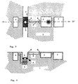
- FIG. 1 shows a schematic view of a preferred one Device for performing the method according to the invention, as it is using near field microscopy.
- FIG. 2 shows a section through the one shown in FIG Embodiment along the line II --- II '.
- a silicon wafer can be a cavity in the form of a capillary or a channel 2 etched.
- the one on one side of the capillary or the channel 2 arranged laser diode 3 is from the capillary or the channel 2 an aperture 4 separated.
- a detector 5 is located below the capillary arranged, which is also through an aperture 4 of the capillary or Channel 2 is separated.
- Control units such as the detector controller 6, the in particular takes over the voltage supply of the detector, or the Laser diode drivers 7 are also integrated on the chip and with the units to be controlled conductively connected.
- FIG. 3 also shows, in schematic form, a top view of a further preferred device for performing the invention Process.
- FIG. 4 shows a section through the arrangement shown in FIG. 3 along the line IV --- IV '.
- the light emitted by the laser diode 3 through a collimation optics 8 (microlens) into a waveguide 9 coupled, at the end of which, for. B. is a second microlens 8.
Landscapes
- Physics & Mathematics (AREA)
- Health & Medical Sciences (AREA)
- General Health & Medical Sciences (AREA)
- General Physics & Mathematics (AREA)
- Nuclear Medicine, Radiotherapy & Molecular Imaging (AREA)
- Radiology & Medical Imaging (AREA)
- Investigating, Analyzing Materials By Fluorescence Or Luminescence (AREA)
Abstract
Description
- Es lassen sich nur Objekte analysieren, die in der optischen Messvorrichtung als Probe zugänglich gemacht werden können.
- Die teuren Herstellkosten der Messvorrichtung sind hinderlich.
- Die Gerätedimension ist unhandlich und eignet sich z.B. wenig für transportable Geräte.
- Eine massive Parallelisierung von Messvolumina ist aufwendig.
- Es werden kostspielige Lasersysteme verwendet.
- z.B. zur Messung bei höheren Konzentrationen sind Messvolumina >lambda zu groß.
- Die konfokale Anordnung des Anregungsvolumens und des Messvolumens bei möglichst kleinen Volumina (<<10-12 I).
- Die Auswertung des Lichtsignals durch Korrelationsmethoden unter Berücksichtigung der Diffusionszeiten der Translation und/oder der Rotation eines Moleküls im Messvolumen.
- eine Vielzahl von Volumenelementen durchgemustert werden soll
- der Rechenaufwand zugunsten der eingesetzten Rechenkapazität und der Rechendauer minimiert werden soll
- die Anzahl der pro Messung erfaßten Volumenelemente und somit das vermessene Gesamtvolumen maximiert werden soll
- Signale von Molekülen, Molekülkomplexen oder Zellen in hoher Verdünnung analysiert werden sollen
- die Präzision der ortsaufgelösten Erfassung von untergeordneter Bedeutung ist
- die Anzahl der ausgesandten Lichtquanten während der Diffusion durch ein einzelnes Messvolumen für eine Korrelation ausreichend ist.
Claims (19)
- Verfahren zur Bestimmung stoffspezifischer Parameter eines oder weniger Moleküle in einer Probe, in derdadurch gekennzeichnet, daßdas Molekül oder die Moleküle in der Probe mittels einer Strahlungsquelle (3) zur Erzeugung elektromagnetischer Excitationsstrahlung zur Abgabe von Emissionstrahlung angeregt wird oder werden,die Emissionsstrahlung des Moleküls oder der Moleküle von einem Detektor (5) zum Erfassen elektromagnetischer Strahlung aufgenommen wird,die Excitations- und/oder Emissionsstrahlung eine für die entsprechende Wellenlänge dieser elektromagnetischen Strahlung durchlässige Einrichtung (4) passiert, die zwischen der Excitationsstrahlenquelle (3) und der Probe und/oder der Probe und einem Detektor (5) angeordnet ist und die mindestens einen Bereich aufweist, dessen größte Ausdehnung senkrecht zur Ausbreitungsrichtung der Excitations- und/oder Emissionsstrahlung kleiner als die Wellenlänge der Ecxitations und/oder Emissionstrahlung ist,die Bestimmung der stoffspezifischen Parameter des Moleküls oder der Moleküle in der Probe mittels Fluoreszenz-Korrelations-Spektroskopie erfolgt.
- Verfahren nach Anspruch 1, dadurch gekennzeichnet, dass die für elektromagnetische Strahlung durchlässige Einrichtung Bereiche in Form von Lochblenden oder Spaltblenden aufweist.
- Verfahren nach mindestens einem der Ansprüche 1 und/oder 2, dadurch gekennzeichnet, dass die für elektromagnetische Strahlung durchlässige Einrichtung Bereiche aufweist, die durch Lichtleiter mit fokussierenden optischen Elementen, wie Mikrolinsen, Gradientenindexlinsen oder binären optischen Elementen optisch koppelbar und/oder in den Lichtleiter integrierbar sind.
- Verfahren nach Anspruch 1 bis 3, wobei die elektromagnetische Strahlung der Emission und/oder Excitation Frequenzen hat, die im typischen Bereich der Chemilumineszenz, Kernfluoreszenz und Röntgenfluoreszenz liegt.
- Verfahren nach mindestens einem der Ansprüche 1 bis 4, wobei die Wechselwirkung der Chemilumineszenz über Koppelung mit anderen physikalischen Effekten wie kernmagnetische Resonanz, elektrischen, magnetischen und elektromagnetischen Feldern (Spektrallinienaufspaltung), Frequenzverdoppelung (SHG, THG), Summen- und Differenzfrequenz, Vibrationseffekte, Koppelung mit Phononen der umgebenden festen Phase beispielsweise Oberflächenplasmonen als Emissionsstrahlung gemessen wird, oder wobei eine Kombination mit atomic force microscopy erfolgt.
- Verfahren nach mindestens einem der Ansprüche 1 bis 5, wobei die Excitationsstrahlung von einer Einheit geliefert wird, die ein Halbleiterlaser oder ein frequenzvervielfachter Halbleiterlaser ist, wobei die erzeugten Lichtpulse gegebenenfalls mittels Wellenleitern, wie Glasfasern verstärkt sind.
- Verfahren nach mindestens einem der Ansprüche 1 bis 6, wobei die Emissionsstrahlung von einer als Photodiode geschalteten pin-Schicht, Lawinenphotodioden oder Photomultiplier detektiert wird.
- Verfahren nach mindestens einem der Ansprüche 1 bis 7, wobei die Quelle der zu detektierenden Strahlung, der Detektor der Strahlung, die Optik und Schaltungselemente auf einem Substrat angeordnet sind.
- Verfahren nach mindestens einem der Ansprüche 1 bis 8, wobei eine Anzahl von Detektoren so angeordnet ist, dass das als Quelle der Emissionsstrahlung dienende Molekül bei Passieren der Detektoren in zeitlicher Korrelation mit dem Passieren beobachtet wird.
- Verfahren nach mindestens einem der Ansprüche 1 bis 9, dadurch gekennzeichnet, dass zur Anregung elektromagnetische Strahlung mit Energien zwischen 284 und 543 eV verwendet wird.
- Verfahren nach mindestens einem der Ansprüche 1 bis 10, dadurch gekennzeichnet, dass die Ausleuchtung von Messvolumina durch Verwendung von holographischen Gittern oder binären optischen Elementen erfolgt.
- Vorrichtung zur Bestimmung stoffspezifischer Parameter nach einem der Ansprüche 1 bis 11, mitdadurch gekennzeichnet, dass die Excitationsstrahlungsquelle (3), die Einrichtung zum Aufnehmen der Probe (2), die durchlässige Einrichtung (4), der Detektor (5) und die elektronischen Schaltelemente (6,7) auf einem Substrat (1) angeordnet sind und die Vorrichtung Auswerteeinheiten zur Analyse der emittierten elektromagnetischen Strahlung mittels Fluoreszenz-Korrelations-Spektroskopie aufweist.einer Einrichtung zum Aufnehmen der Probe (2),einer Excitationsstrahlungsquelle (3) zur Erzeugung elektromagnetischer Excitationsstrahlung zum Anregen des Moleküls oder der Moleküle in einer Probe in einem Excitationsstrahlengang,einem Detektor (5) zum Erfassen von elektromagnetischer Strahlung in einem Emissionsstrahlengang;einer im Strahlengang der Excitations- und/oder Emissionsstrahlung befindlichen, für die entsprechende Wellenlänge dieser elektromagnetischen Strahlung durchlässige Einrichtung (4), wobei diese Einrichtung (4) mindestens einen Bereich aufweist, dessen größte Ausdehnung senkrecht zur Ausbreitungsrichtung der Excitations- und/oder Emissionsstrahlung kleiner als die Wellenlänge der Excitations- und/oder Emissionsstrahlung ist, und elektronischen Schaltelementen (6,7)
- Vorrichtung nach Anspruch 12, wobei die für elektromagnetische Strahlung durchlässige Einrichtung (4) Bereiche in Form von Lochblenden oder Spaltblenden aufweist.
- Vorrichtung nach mindestens einem der Ansprüche 12 und/oder 13, wobei die für elektromagnetische Strahlung durchlässige Einrichtung (4) Bereiche aufweist, die durch Lichtleiter mit fokussierenden optischen Elementen, wie Mikrolinsen, Gradientenindexlinsen oder binären optischen Elementen optisch koppelbar und/oder in den Lichtleiter integrierbar sind.
- Vorrichtung nach mindestens einem der Ansprüche 12 bis 14, wobei das Substrat ein Sillciumwafer ist.
- Vorrichtung nach mindestens einem der Ansprüche 12 bis 15, wobei der Detektor (5) als Photodetektor ausgestaltet ist und am Boden eines das Substrat durchziehenden Kanals angeordnet ist und die Excitationsstrahlungsquelle in einem 0° < Winkel < 180° zu der Detektionseinheit eingestrahlt werden kann.
- Vorrichtung nach einem der Ansprüche 12 bis 16, in der Anregungsund Detektionseinheit konfokal auf einem Substrat integriert sind. .
- Vorrichtung nach mindestens einem der Ansprüche 12 bis 17, dadurch gekennzeichnet, dass die Detektoreeinheit (5) als Multidetektoreneinheit ausgebildet ist.
- Vorrichtung nach einem der Ansprüche 12 bis 18, dadurch gekennzeichnet, dass das Substrat (1) ein piezo-elektrisches Element ist.
Applications Claiming Priority (3)
| Application Number | Priority Date | Filing Date | Title |
|---|---|---|---|
| DE4438391A DE4438391C2 (de) | 1994-10-27 | 1994-10-27 | Vorrichtung zur Bestimmung stoffspezifischer Parameter eines oder weniger Moleküle mittels Korrelations-Spektroskopie |
| DE4438391 | 1994-10-27 | ||
| PCT/EP1995/004213 WO1996013744A1 (de) | 1994-10-27 | 1995-10-26 | Verfahren und vorrichtung zur bestimmung stoffspezifischer parameter eines oder weniger moleküle mittels korrelations-spektroskopie |
Publications (2)
| Publication Number | Publication Date |
|---|---|
| EP0788615A1 EP0788615A1 (de) | 1997-08-13 |
| EP0788615B1 true EP0788615B1 (de) | 2002-09-18 |
Family
ID=6531840
Family Applications (1)
| Application Number | Title | Priority Date | Filing Date |
|---|---|---|---|
| EP95937851A Expired - Lifetime EP0788615B1 (de) | 1994-10-27 | 1995-10-26 | Verfahren und vorrichtung zur bestimmung stoffspezifischer parameter eines oder weniger moleküle mittels korrelations-spektroskopie |
Country Status (4)
| Country | Link |
|---|---|
| US (1) | US5933233A (de) |
| EP (1) | EP0788615B1 (de) |
| DE (2) | DE4438391C2 (de) |
| WO (1) | WO1996013744A1 (de) |
Cited By (4)
| Publication number | Priority date | Publication date | Assignee | Title |
|---|---|---|---|---|
| US9649061B2 (en) | 2015-03-10 | 2017-05-16 | Becton, Dickinson And Company | Biological fluid micro-sample management device |
| US9678065B2 (en) | 2013-01-11 | 2017-06-13 | Becton, Dickinson And Company | Low-cost point-of-care assay device |
| US9693723B2 (en) | 2014-10-14 | 2017-07-04 | Becton, Dickinson And Company | Blood sample management using open cell foam |
| US11298061B2 (en) | 2014-10-14 | 2022-04-12 | Becton, Dickinson And Company | Blood sample management using open cell foam |
Families Citing this family (45)
| Publication number | Priority date | Publication date | Assignee | Title |
|---|---|---|---|---|
| DE19648458C1 (de) | 1996-11-22 | 1998-07-09 | Evotec Biosystems Gmbh | Mikromechanische Ejektionspumpe zum Heraustrennen kleinster Fluidvolumina aus einem strömenden Probenfluid |
| DE19649048C1 (de) * | 1996-11-27 | 1998-04-09 | Evotec Biosystems Gmbh | Verfahren zur Unterscheidung oder Erfassung von Partikeln in einer Probe durch Identifizierung von Signalabschnitten zeitaufgelöster, optischer Rohsignale aus der Probe auf Basis von Einzelphotonendetektion |
| EP0884583A1 (de) * | 1997-06-10 | 1998-12-16 | Evotec BioSystems GmbH | Verfahren zur Charakterisierung von Proben in einem mindestens zweidimensionalen Raum spezifischer physikalischer Eigenschaften |
| US5973316A (en) * | 1997-07-08 | 1999-10-26 | Nec Research Institute, Inc. | Sub-wavelength aperture arrays with enhanced light transmission |
| DE19729245C1 (de) * | 1997-07-09 | 1999-05-06 | Evotec Biosystems Ag | Spiegelobjektiv und dessen Verwendung |
| US6040936A (en) * | 1998-10-08 | 2000-03-21 | Nec Research Institute, Inc. | Optical transmission control apparatus utilizing metal films perforated with subwavelength-diameter holes |
| US6236033B1 (en) | 1998-12-09 | 2001-05-22 | Nec Research Institute, Inc. | Enhanced optical transmission apparatus utilizing metal films having apertures and periodic surface topography |
| US20030096433A1 (en) * | 1999-03-03 | 2003-05-22 | Evotec Analytical Systems Gmbh | Homogeneous fluorescence assay |
| DE19941270C1 (de) * | 1999-08-31 | 2001-06-28 | Lienhard Pagel | Mikrofluidisches pH-Sensormodul |
| WO2001023894A1 (de) * | 1999-09-28 | 2001-04-05 | Evotec Oai Ag | Quantitative analyse und typisierung subzellulärer partikel |
| JP2001108619A (ja) * | 1999-10-12 | 2001-04-20 | Minolta Co Ltd | 分析装置、試料操作針および試料取り出し方法 |
| US6285020B1 (en) | 1999-11-05 | 2001-09-04 | Nec Research Institute, Inc. | Enhanced optical transmission apparatus with improved inter-surface coupling |
| NL1015640C2 (nl) * | 2000-07-06 | 2002-01-08 | Univ Delft Tech | Inrichting en werkwijze voor het bepalen van de vorm en/of grootte van kleine deeltjes. |
| US6441298B1 (en) | 2000-08-15 | 2002-08-27 | Nec Research Institute, Inc | Surface-plasmon enhanced photovoltaic device |
| JP2004538396A (ja) * | 2001-08-10 | 2004-12-24 | マクス、ベグル、バウウンテルネームング、ゲゼルシャフト、ミット、ベシュレンクテル、ハフツング、ウント、コンパニー、コマンディトゲゼルシャフト | 固定式軌道 |
| GB2383127B (en) * | 2001-12-12 | 2004-10-20 | Proimmune Ltd | Device and method for investigating analytes in liquid suspension or solution |
| US6649901B2 (en) | 2002-03-14 | 2003-11-18 | Nec Laboratories America, Inc. | Enhanced optical transmission apparatus with improved aperture geometry |
| US6867420B2 (en) * | 2002-06-03 | 2005-03-15 | The Regents Of The University Of California | Solid-state detector and optical system for microchip analyzers |
| WO2005008212A2 (en) * | 2003-06-20 | 2005-01-27 | The Regents Of The University Of California | Modulated excitation fluorescence analysis |
| DE10336080A1 (de) * | 2003-08-06 | 2005-03-03 | Gnothis Holding Sa | Verfahren und Vorrichtung zur Bestimmung von lumineszierenden Molekülen, insbesondere nach der Methode der Fluoreszenzkorrelationsspektroskopie |
| JP2007508810A (ja) | 2003-09-30 | 2007-04-12 | エヴォテック ニューロサイエンシス ゲゼルシャフト ミット ベシュレンクテル ハフツング | スルホトランスフェラーゼの神経変性疾患に関する診断的および治療的使用 |
| EP1721194A4 (de) * | 2003-12-05 | 2010-01-13 | Univ Pittsburgh | Metallische nanooptische linsen und strahlformungseinrichtungen |
| US7221455B2 (en) * | 2004-01-20 | 2007-05-22 | The Regents Of The Unversity Of California | Integrated, fluorescence-detecting microanalytical system |
| JP2008508893A (ja) | 2004-08-11 | 2008-03-27 | エボテツク・ニユーロサイエンシーズ・ゲー・エム・ベー・ハー | 形質膜atpアーゼの診断及び治療への使用 |
| EP1784678A2 (de) | 2004-08-19 | 2007-05-16 | University of Pittsburgh | Optische spektralanalysatoren auf chipmassstab mit verbesserter auflösung |
| WO2006125830A2 (en) | 2005-05-27 | 2006-11-30 | Evotec Neurosciences Gmbh | Kcnn3 as diagnostic and therapeutic target for neurodegenerative diseases |
| ATE534751T1 (de) | 2005-05-30 | 2011-12-15 | Takeda Pharmaceutical | Verwendung von prkx zur diagnose und therapie von alzheimer krankheit |
| US7767444B2 (en) * | 2005-05-31 | 2010-08-03 | Nanyang Technological University | Cell analysis using laser with external cavity |
| US20090133135A1 (en) | 2005-06-01 | 2009-05-21 | Evotec Neurosciences Gmbh | Diagnostic and Therapeutic Target SLC39A11 Proteins for Neurodegenerative Diseases |
| WO2006134128A2 (en) | 2005-06-16 | 2006-12-21 | Evotec Neurosciences Gmbh | Diagnostic and therapeutic target adarb2 proteins for neurodegenerative diseases |
| US7719685B2 (en) * | 2006-11-30 | 2010-05-18 | Chian Chiu Li | Near-field optical apparatus and method using photodetector array |
| US9164037B2 (en) | 2007-01-26 | 2015-10-20 | Palo Alto Research Center Incorporated | Method and system for evaluation of signals received from spatially modulated excitation and emission to accurately determine particle positions and distances |
| US8821799B2 (en) | 2007-01-26 | 2014-09-02 | Palo Alto Research Center Incorporated | Method and system implementing spatially modulated excitation or emission for particle characterization with enhanced sensitivity |
| EP2053397A1 (de) | 2007-10-25 | 2009-04-29 | EVOTEC Neurosciences GmbH | PPM1E-Proteine und Nukleinsäuren als Targets für neurodegenerative Erkrankungen |
| US8373860B2 (en) | 2008-02-01 | 2013-02-12 | Palo Alto Research Center Incorporated | Transmitting/reflecting emanating light with time variation |
| US8629981B2 (en) | 2008-02-01 | 2014-01-14 | Palo Alto Research Center Incorporated | Analyzers with time variation based on color-coded spatial modulation |
| EP2186827A1 (de) | 2008-11-14 | 2010-05-19 | HS LifeSciences Ltd. | Ersatzmarkergerichtetes cDNA-Klonen von selektiv induzierten mRNAs |
| US8723140B2 (en) | 2011-08-09 | 2014-05-13 | Palo Alto Research Center Incorporated | Particle analyzer with spatial modulation and long lifetime bioprobes |
| US9029800B2 (en) | 2011-08-09 | 2015-05-12 | Palo Alto Research Center Incorporated | Compact analyzer with spatial modulation and multiple intensity modulated excitation sources |
| WO2013075031A1 (en) | 2011-11-16 | 2013-05-23 | Becton, Dickinson And Company | Methods and systems for detecting an analyte in a sample |
| CN106029863A (zh) | 2013-11-06 | 2016-10-12 | 贝克顿·迪金森公司 | 微流体性装置和制造和使用其的方法 |
| AU2014348910B2 (en) | 2013-11-13 | 2017-04-20 | Becton, Dickinson And Company | Optical imaging system and methods for using the same |
| CN103824813B (zh) * | 2014-03-05 | 2016-05-11 | 陈龙 | 一种单片集成的微荧光分析系统及其制作方法 |
| WO2017040650A1 (en) | 2015-09-01 | 2017-03-09 | Becton, Dickinson And Company | Depth filtration device for separating specimen phases |
| US11009464B2 (en) * | 2015-12-11 | 2021-05-18 | International Business Machines Corporation | Smartphone compatible on-chip biodetection using integrated optical component and microfluidic channel with nanopillar array |
Family Cites Families (8)
| Publication number | Priority date | Publication date | Assignee | Title |
|---|---|---|---|---|
| GB8617431D0 (en) * | 1986-07-17 | 1986-08-28 | Atomic Energy Authority Uk | Sensor |
| DD271953A1 (de) * | 1988-05-09 | 1989-09-20 | Zeiss Jena Veb Carl | Einrichtung zur automatischen photometrischen analyse kleinster probenmengen |
| GB8920571D0 (en) * | 1989-09-12 | 1989-10-25 | Carr Robert J G | Examination of objects of macromolecular size |
| US5288999A (en) * | 1990-11-19 | 1994-02-22 | At&T Bell Laboratories | Manufacturing method including near-field optical microscopic examination of a semiconductor wafer |
| JP2823970B2 (ja) * | 1991-04-05 | 1998-11-11 | 浜松ホトニクス株式会社 | 近接場走査光学顕微鏡 |
| DE4128846C2 (de) * | 1991-08-30 | 1994-07-14 | Rainer Dr Klein | Integriert optischer Stoffsensor |
| EP0679251B1 (de) * | 1993-01-18 | 1998-04-08 | Evotec BioSystems GmbH | Verfahren und vorrichtung zur bewertung der fitness von biopolymeren |
| US5446534A (en) * | 1993-03-05 | 1995-08-29 | Optical Solutions, Inc. | Broad band waveguide spectrometer |
-
1994
- 1994-10-27 DE DE4438391A patent/DE4438391C2/de not_active Expired - Lifetime
-
1995
- 1995-10-26 EP EP95937851A patent/EP0788615B1/de not_active Expired - Lifetime
- 1995-10-26 US US08/836,032 patent/US5933233A/en not_active Expired - Lifetime
- 1995-10-26 WO PCT/EP1995/004213 patent/WO1996013744A1/de not_active Ceased
- 1995-10-26 DE DE59510381T patent/DE59510381D1/de not_active Expired - Lifetime
Cited By (9)
| Publication number | Priority date | Publication date | Assignee | Title |
|---|---|---|---|---|
| US9678065B2 (en) | 2013-01-11 | 2017-06-13 | Becton, Dickinson And Company | Low-cost point-of-care assay device |
| US9693723B2 (en) | 2014-10-14 | 2017-07-04 | Becton, Dickinson And Company | Blood sample management using open cell foam |
| US10219731B2 (en) | 2014-10-14 | 2019-03-05 | Becton, Dickinson And Company | Blood sample management using open cell foam |
| US10595762B2 (en) | 2014-10-14 | 2020-03-24 | Becton, Dickinson And Company | Blood sample management using open cell foam |
| US11134875B2 (en) | 2014-10-14 | 2021-10-05 | Becton, Dickinson And Company | Blood sample management using open cell foam |
| US11298061B2 (en) | 2014-10-14 | 2022-04-12 | Becton, Dickinson And Company | Blood sample management using open cell foam |
| US12533061B2 (en) | 2014-10-14 | 2026-01-27 | Becton, Dickinson And Company | Blood sample management using open cell foam |
| US9649061B2 (en) | 2015-03-10 | 2017-05-16 | Becton, Dickinson And Company | Biological fluid micro-sample management device |
| US9873117B2 (en) | 2015-03-10 | 2018-01-23 | Becton, Dickinson And Company | Biological fluid micro-sample management device |
Also Published As
| Publication number | Publication date |
|---|---|
| DE59510381D1 (de) | 2002-10-24 |
| US5933233A (en) | 1999-08-03 |
| WO1996013744A1 (de) | 1996-05-09 |
| DE4438391C2 (de) | 1997-07-03 |
| EP0788615A1 (de) | 1997-08-13 |
| DE4438391A1 (de) | 1996-05-02 |
Similar Documents
| Publication | Publication Date | Title |
|---|---|---|
| DE4438391C2 (de) | Vorrichtung zur Bestimmung stoffspezifischer Parameter eines oder weniger Moleküle mittels Korrelations-Spektroskopie | |
| EP0822395B1 (de) | Verfahren und Vorrichtung zur Raman-Korrelationsspektroskopie | |
| EP0762114A2 (de) | Vorrichtung für parallele Zweiphotonen-Fluoreszenz-Korrelations-Spektroskopiemessungen (TPA-FCS) an mehreren Proben und deren Verwendung zum Wirkstoff-Screening | |
| EP0834066B1 (de) | Verfahren und einrichtung zum nachweis physikalischer, chemischer, biologischer oder biochemischer reaktionen und wechselwirkungen | |
| EP1511989B1 (de) | Fluoreszenzmesssystem | |
| EP2652481A2 (de) | Vorrichtung zur photometrischen bzw. spektrometrischen untersuchung einer flüssigen probe | |
| EP2895844A1 (de) | Vorrichtung mit einer anordnung optischer elemente | |
| EP1678547B1 (de) | Vorrichtung und verfahren zur messung optischer eigenschaften eines objekts | |
| DE60205406T2 (de) | Optisches zweiwellenlängen-fluoreszenzanalysegerät | |
| DE19729245C1 (de) | Spiegelobjektiv und dessen Verwendung | |
| EP3704473B1 (de) | Neuartiger sensor für die ramanspektroskopie | |
| EP1259797B1 (de) | Vorrichtung zur optischen spektroskopie und verfahren zu dessen herstellung | |
| DE102008014335B4 (de) | Vorrichtung und Verfahren zur Bestimmung einer Brechzahl eines Messobjekts | |
| EP3172542B1 (de) | Anordnung zur orts- und wellenlängenaufgelösten erfassung von lichtstrahlung, die von mindestens einer oled oder led emittiert wird | |
| EP1504251A1 (de) | Vorrichtung und verfahren zur untersuchung chemischer und/oder biologischer proben | |
| DE102020210245B3 (de) | Gradiometer zur Erfassung eines Gradientenfeldes einer physikalischen Größe | |
| WO2001040769A2 (de) | Hochdurchsatzscreening-verfahren und -vorrichtung zur optischen erfassung von proben | |
| DE10017824A1 (de) | Vorrichtung zur parallelen photometrischen Fluoreszenz- oder Limineszenzanalyse mehrerer voneinander getrennter Probenbereiche auf einem Objekt | |
| DE102019106194B4 (de) | Vorrichtung zur spektroskopischen Bestimmung der Bindungskinetik eines Analyten | |
| DE3233055C2 (de) | Durchflußvorrichtung zur Untersuchung einzelner, in einer Flüssigkeit suspendierter Teilchen | |
| DE10058577C2 (de) | Verfahren und Vorrichtung für die Fluoreszenzkorrelationsspektroskopie zur Verstärkung der Fluoreszenzintensität | |
| DE19905714A1 (de) | Ultrakleines Spektroskopiemikroskop | |
| WO2006056168A1 (de) | Vorrichtung und verfahren zur messung von fluoreszenz in mehreren reaktionsräumen | |
| DE112021003493T5 (de) | Vorrichtung zur Bestimmung der Anwesenheit oder Konzentration von Zielmolekülen | |
| DE19860549A1 (de) | Scanning-mikroskopisches Verfahren mit hoher axialer Auflösung |
Legal Events
| Date | Code | Title | Description |
|---|---|---|---|
| PUAI | Public reference made under article 153(3) epc to a published international application that has entered the european phase |
Free format text: ORIGINAL CODE: 0009012 |
|
| 17P | Request for examination filed |
Effective date: 19970418 |
|
| AK | Designated contracting states |
Kind code of ref document: A1 Designated state(s): CH DE FR GB LI |
|
| 17Q | First examination report despatched |
Effective date: 19980706 |
|
| RAP1 | Party data changed (applicant data changed or rights of an application transferred) |
Owner name: EVOTEC BIOSYSTEMS AKTIENGESELLSCHAFT |
|
| GRAG | Despatch of communication of intention to grant |
Free format text: ORIGINAL CODE: EPIDOS AGRA |
|
| RAP1 | Party data changed (applicant data changed or rights of an application transferred) |
Owner name: EVOTEC OAI AG |
|
| GRAG | Despatch of communication of intention to grant |
Free format text: ORIGINAL CODE: EPIDOS AGRA |
|
| GRAG | Despatch of communication of intention to grant |
Free format text: ORIGINAL CODE: EPIDOS AGRA |
|
| GRAH | Despatch of communication of intention to grant a patent |
Free format text: ORIGINAL CODE: EPIDOS IGRA |
|
| GRAH | Despatch of communication of intention to grant a patent |
Free format text: ORIGINAL CODE: EPIDOS IGRA |
|
| GRAA | (expected) grant |
Free format text: ORIGINAL CODE: 0009210 |
|
| AK | Designated contracting states |
Kind code of ref document: B1 Designated state(s): CH DE FR GB LI |
|
| PG25 | Lapsed in a contracting state [announced via postgrant information from national office to epo] |
Ref country code: FR Free format text: LAPSE BECAUSE OF FAILURE TO SUBMIT A TRANSLATION OF THE DESCRIPTION OR TO PAY THE FEE WITHIN THE PRESCRIBED TIME-LIMIT Effective date: 20020918 |
|
| REG | Reference to a national code |
Ref country code: GB Ref legal event code: FG4D Free format text: NOT ENGLISH |
|
| REG | Reference to a national code |
Ref country code: CH Ref legal event code: EP |
|
| REG | Reference to a national code |
Ref country code: CH Ref legal event code: NV Representative=s name: SCHMAUDER & PARTNER AG PATENTANWALTSBUERO |
|
| REF | Corresponds to: |
Ref document number: 59510381 Country of ref document: DE Date of ref document: 20021024 |
|
| GBT | Gb: translation of ep patent filed (gb section 77(6)(a)/1977) |
Effective date: 20030113 |
|
| EN | Fr: translation not filed | ||
| PLBE | No opposition filed within time limit |
Free format text: ORIGINAL CODE: 0009261 |
|
| STAA | Information on the status of an ep patent application or granted ep patent |
Free format text: STATUS: NO OPPOSITION FILED WITHIN TIME LIMIT |
|
| 26N | No opposition filed |
Effective date: 20030619 |
|
| REG | Reference to a national code |
Ref country code: CH Ref legal event code: PCAR Free format text: SCHMAUDER & PARTNER AG PATENT- UND MARKENANWAELTE VSP;ZWAENGIWEG 7;8038 ZUERICH (CH) |
|
| PGFP | Annual fee paid to national office [announced via postgrant information from national office to epo] |
Ref country code: GB Payment date: 20141024 Year of fee payment: 20 Ref country code: DE Payment date: 20141204 Year of fee payment: 20 Ref country code: CH Payment date: 20141024 Year of fee payment: 20 |
|
| REG | Reference to a national code |
Ref country code: DE Ref legal event code: R071 Ref document number: 59510381 Country of ref document: DE |
|
| REG | Reference to a national code |
Ref country code: CH Ref legal event code: PL |
|
| REG | Reference to a national code |
Ref country code: CH Ref legal event code: PL |
|
| REG | Reference to a national code |
Ref country code: GB Ref legal event code: PE20 Expiry date: 20151025 |
|
| PG25 | Lapsed in a contracting state [announced via postgrant information from national office to epo] |
Ref country code: GB Free format text: LAPSE BECAUSE OF EXPIRATION OF PROTECTION Effective date: 20151025 |