EP0788598B1 - Appareil pour le controle d'une suspension d'un materiau susceptible de fluorescence - Google Patents
Appareil pour le controle d'une suspension d'un materiau susceptible de fluorescence Download PDFInfo
- Publication number
- EP0788598B1 EP0788598B1 EP95934596A EP95934596A EP0788598B1 EP 0788598 B1 EP0788598 B1 EP 0788598B1 EP 95934596 A EP95934596 A EP 95934596A EP 95934596 A EP95934596 A EP 95934596A EP 0788598 B1 EP0788598 B1 EP 0788598B1
- Authority
- EP
- European Patent Office
- Prior art keywords
- test tube
- radiation
- suspension
- test
- emerging
- Prior art date
- Legal status (The legal status is an assumption and is not a legal conclusion. Google has not performed a legal analysis and makes no representation as to the accuracy of the status listed.)
- Expired - Lifetime
Links
Images


Classifications
-
- G—PHYSICS
- G01—MEASURING; TESTING
- G01N—INVESTIGATING OR ANALYSING MATERIALS BY DETERMINING THEIR CHEMICAL OR PHYSICAL PROPERTIES
- G01N27/00—Investigating or analysing materials by the use of electric, electrochemical, or magnetic means
- G01N27/72—Investigating or analysing materials by the use of electric, electrochemical, or magnetic means by investigating magnetic variables
- G01N27/82—Investigating or analysing materials by the use of electric, electrochemical, or magnetic means by investigating magnetic variables for investigating the presence of flaws
- G01N27/83—Investigating or analysing materials by the use of electric, electrochemical, or magnetic means by investigating magnetic variables for investigating the presence of flaws by investigating stray magnetic fields
- G01N27/84—Investigating or analysing materials by the use of electric, electrochemical, or magnetic means by investigating magnetic variables for investigating the presence of flaws by investigating stray magnetic fields by applying magnetic powder or magnetic ink
Definitions
- the invention relates to a system for checking a suspension of solid particles in a test tube for recording the suspension and to let it settle therein.
- Suspensions of solid particles in liquids frequently used in technical areas are suspensions of barium sulfate in liquid as a contrast medium for X-ray inspection systems, magnetisable, fluorescent particles in liquids for the Crack test; Lubricating oils that increase the solids content over time exhibit metallic abrasion, abrasive suspensions and so on.
- suspensions are circulated in plants - for example as a lubricant or fluorescent Liquid in crack testing systems.
- the integrity of these suspensions depends among other things the reliability of the test system - if there are too few solid particles or mechanical particles Load are damaged, are those received with them Tests are often bad or no longer usable.
- Tests are often bad or no longer usable.
- it's both environmental and cost-effective desired to use the suspension as long as possible to avoid unnecessary disposal.
- EP-A-0 427 996 describes a method for determination aromatic hydrocarbons become known, wherein Fluorescence spectroscopy to determine the concentration more fluorescent, i.e. liquid dissolved aromatics is used. So here are clear liquids and no suspensions measured.
- DE-A-43 11 543 relates to a device for determination the concentration of a test liquid that is only the Luminescence, i.e. the one released by the test liquid Light, but not whether this luminescence is possible changes over time and therefore does not allow Statement about whether the luminescence is due to rubbed fluorescent material or through the particles themselves, to which the fluorescent material is bound occurs.
- This publication also does not allow measurements of the Solid density of the suspension since the emission of Fluorescent light does not allow such statements.
- JP-A-62-255851 in turn relates to the measurement of a Sedimentation speed of a material, as in Coagulation measuring devices for example for the Solvent coagulation of plastics is required. It is the increase in size of the suspended particles measured over time.
- the field of the invention relates in contrast to the measurement of fluorescent material, that may decrease in size over time.
- an excitation radiation source with radiation in the fluorescence / phosphorescence excitation wavelength range
- a test tube transparent to the illuminating radiation and the fluorescence and / or phosphorescence radiation emerging therefrom.
- test equipment in which test equipment is allowed to sit, which can be arranged in the beam path of the system, possibly a further test tube (P E ) for the illuminating radiation and the fluorescent and / or phosphorescent radiation emerging therefrom, in which a comparative or let calibration liquid settle, which can be arranged in the beam path of the system; a sensor device for detecting the illuminating radiation (S L ); a sensor device for detecting the radiation emerging from the test tube (s) (P E , P) in transmission (S T ); a sensor device for detecting the fluorescence and / or phosphorescence radiation (SF) emerging from the test tube (s); a timer device (U) which makes it possible to take measured values after predeterminable periods of time and to store them accordingly; and a computer unit (R) for processing the measured values obtained and outputting at least one output signal to the processing unit.
- P E further test tube
- S L sensor device for detecting the illuminating radiation
- S T a sensor device for detecting the radiation
- the system according to the invention is arranged so that the test tube (P) in the bypass of a continuous suspension circulating system is connected, i.e. a permanent - also automatable - monitoring of the test equipment and also the documentation of the monitoring values for the fulfillment of documentation obligations is possible.
- the fluorescent solid material of the test medium suspension preferably has particles connected to fluorescent or phosphorescent dye. It can be favorable if the wavelength of the illumination source has only a small bandwidth, for example by connecting a band filter or using a laser - this can more reliably rule out interference effects from other wavelength ranges.
- the wavelengths at least in the range the excitation wavelengths exclude protected sensors.
- the computer unit (R) usually processes the Measured values of the transmission radiation and that from the test tube emerging radiation at an angle of not 180 ° predeterminable time periods, compares the thus obtained Values with a saved evaluation table and produced at least one corresponding output signal.
- This at least one output signal from the computer unit (R) is connected to a display device (D), such as an acoustic signal generator, a monitor, a pointer instrument or the like.
- At least one output signal from the computer unit is preferred (R) to control suspension renewal; Suspension supplement or to switch off with the suspension working system used.
- At least one output signal is preferably in a recording unit for the creation of permanent records on storage media such as printouts, test documents or CD-Rom etc. passed the test documents on the quality of the fluorescent suspension under the recording conditions create.
- the display / viewing device (20) or a corresponding device is preferred Data display device for at least one recording device permanent recording of the signal (s) produced, such as a printer or the like is connected downstream.
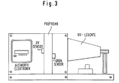
- FIGS. 1 and 3 are systems which are now used as an additional device in a cost control package and / or security documentation as an additive in a, in particular automatically operating, crack detection test system in which a lamp L the test tube P is irradiated as the radiation source and the radiation (ST) passing through it is measured in transmission, preferably 180 ° to the direction of irradiation.
- a further sensor SF is provided for radiation not emerging in the transmission direction, this sensor SF either measuring only certain wavelengths of the emerging light by measures known per se (by connecting up band filters) or else the total radiation.
- Both values determined by the sensors are passed together with a timer value (U) into the computer R, which then processes them into at least one output signal, which can then be used on printers, display instruments, as a control signal for dependent systems, etc.
- a more complex system is shown, which enables the simultaneous checking of a test device in a calibration test tube.
- Known calibration fluid for example unused test equipment - but also a white standard or the like can be introduced into this calibration test tube so that there is a fixed reference for the measurement.
- the radiation source can be used by known measures (beam splitters etc.) to illuminate both test tubes evenly - the same applies to the sensors.
- the internal standard results in an even higher accuracy of the measurement.
- the devices according to the invention are preferred in a manner known per se Workpieces for the magnetic powder process magnetized with a dye, especially fluorescent dyes having ferromagnetic material, such as iron or Test compound containing iron compound with enrichment the iron particles sprayed on surface defects, under UV or viewed visible light and the crack image thus obtained with the crack image on at least one control test specimen is compared.
- a dye especially fluorescent dyes having ferromagnetic material, such as iron or Test compound containing iron compound with enrichment the iron particles sprayed on surface defects, under UV or viewed visible light and the crack image thus obtained with the crack image on at least one control test specimen is compared.
- ASTM bulb an automated test equipment, as "Automated” called ASTM bulb, can be provided ensure that changes in the test equipment suspension, which consists of a liquid with ferromagnetic, suspended therein preferably with a fluorescent dye stained particles, such as those caused by abrasion or decay of the ferromagnetic particles with prolonged circulation of the Liquid, release of the dye on the particles or also loss of magnetic particles on the different measured test specimens remain, recognized and accordingly can be traded. So then either new suspension inserted, ferromagnetic powder in the suspension be delivered or at least reordered will.
- test equipment e.g. B. the fluorescent concentrate yellow-green of the applicant, which contains additives
- ASTM pear a known pear-shaped control container
- the associated values are the Known to those skilled in the art. (see in particular Fig. 4). So here it comes down to a day or the like.
- Test equipment For the initial cost-based recording of the material parameter Test equipment becomes the test equipment by measuring the optical Density and fluorescence behavior - preferably in regular Periods automatically - checked.
- test medium suspension is which consist of a liquid carrier and ferromagnetic, fluorescent particles consists of the test medium circuit branched off the test system, into a test tube or Brought cuvette and left there, so that there is a resting, results in non-turbulent liquid for testing. There then the density of this quiescent liquid in transmission with known sensor and the fluorescence on one the wavelength of the fluorescence radiation (here in the green area, because the fluorescence occurs there) measured at the same time. It will be at different times Delayed from the introduction of test equipment into the test tube Measured values determined. In any case, an initial value of Transmission and fluorescence after introduction of the fluid test medium suspension into the test tube and at least one other Value for T and F at time T after insertion measured.
- the following quantities can be measured with meaningfulness by the test equipment test unit, which then lead to an output signal of the test equipment test unit, which indicates the usability of the test equipment:
- Dirt in the test equipment - for example, abrasion from workpieces, etc. shows itself as falling transmission and falling fluorescence at the start of measurement (T 0 );
- Water input shows up as increasing transmission at (T 0 ) and water output as higher concentration of particles, i.e. decreasing transmission and increasing fluorescence.
- test tube be self-cleaning Flow cell is formed - that is, at the end new liquid flows through the test tube and so the same cleanses. It can also have a separate CIP unit (Cleaning-in process) for test tubes may not be provided contaminants removable by the test equipment, such as burned or polymerized organic compounds which are used for Contamination of the test tube and thus falsification of Measurements can solve.
- a display device or digital data display device can this be a writing instrument, e.g. B. a laser printer or an inkjet recorder.
- the security and control document also allows a more secure one Follow-up inspection of people working on vision devices Operators so that e.g. B. hit in a night shift Assessments of the marking element 20d in the color fields are verifiable and, if necessary, can be corrected.
- the acquisition of the data flow based on brightness values can also be used advantageously instead of a camera a diode cell or other suitable means such as that Experts are familiar, happen.
- a camera a diode cell or other suitable means
Claims (10)
- Installation pour contrôler une suspension de particules de matière solide dans un tube à essai pour recevoir la suspension et pour laisser se déposer celle-ci dans celui-ci, comportant :une source de rayonnement d'éclairage (L),un tube à essai (P) transparent pour le rayonnement d'éclairage et le rayonnement sortant de celui-ci, tube qui peut être agencé dans le trajet des rayons de l'installation,le cas échéant, un autre tube à essai (PE) transparent pour le rayonnement d'éclairage et le rayonnement sortant de celui-ci, tube dans lequel un liquide de comparaison ou d'étalonnage est laissé se déposer, tube qui peut être agencé dans le trajet des rayons de l'installation,un dispositif capteur pour détecter le rayonnement d'éclairage (SL),un dispositif capteur pour détecter le rayonnement (ST) sortant du ou des tubes à essais (PE,P) en transmission,un dispositif capteur pour détecter le rayonnement (SF) sortant du ou des tubes à essai sous un angle différent de 180°,un dispositif d'horloge (U) pour permettre la réception de valeurs de mesure mesurées à des intervalles temporels sur la même suspension de matière solide introduite dans le tube à essai et pour introduire une nouvelle suspension de matière solide après des intervalles de temps à chaque fois prédéterminés, etune unité de calcul (R) pour traiter les valeurs de mesure obtenues et émettre au moins un signal de sortie.
- Installation selon la revendication 1,
caractérisée en ce que, pour contrôler une suspension d'une matière fluorescente ou phosphorescente :la source de rayonnement fournit un rayonnement dans la plage de longueurs d'onde de l'excitation de la fluorescence ou de la phosphorescence de la matière solide, etle ou les tubes à essai sont transparents pour le rayonnement d'éclairage et le rayonnement fluorescent et/ou phosphorescent sortant de celui-ci ou de ceux-ci. - Installation selon la revendication 1 ou 2,
caractérisée en ce que le tube à essai (P) est raccordé en dérivation d'une installation faisant circuler de façon continue la suspension. - Installation selon l'une des revendications précédentes,
caractérisée en ce que la longueur d'onde de la source d'éclairage présente une faible largeur de bande, par exemple par mise en place en amont d'un filtre passe-bande ou par utilisation d'un laser. - Installation selon une des revendications 2 à 4,
caractérisée en ce que, comme dispositif capteur pour mesurer la fluorescence/phosphorescence (SF) par des filtres passe-bande ou des filtres à arêtes, qui excluent des longueurs d'onde au moins dans la plage des longueurs d'onde d'excitation, sont utilisés des capteurs protégés. - Installation selon une des revendications précédentes,
caractérisée en ce que l'unité de calcul (R) traite les valeurs de mesure du rayonnement de transmission et du rayonnement sortant du tube à essai sous un angle différent de 180° après des intervalles de temps pouvant être prédéterminés, compare les valeurs ainsi obtenues avec un tableau d'évaluation mémorisé et fournit au moins un signal de sortie correspondant. - Installation selon une des revendications précédentes,
caractérisée en ce qu'au moins un signal de sortie de l'unité de calcul (R) est fourni à un appareil d'affichage (D), comme un dispositif de transmission de signaux acoustique, un moniteur, un instrument à cadran ou analogue. - Installation selon une des revendications précédentes,
caractérisée en ce qu'au moins un signal de sortie de l'unité de calcul (R) est utilisé pour commander un renouvellement de la suspension, un recomplètement de la suspension, ou pour couper l'installation travaillant avec la suspension. - Installation selon une des revendications précédentes,
caractérisée en qu'au moins un signal de sortie est amené dans une unité d'enregistrement pour établir des enregistrements permanents sur des moyens de mémorisation, comme des imprimés, des documents de contrôle ou des CD-ROM etc..., qui établissent des documents de contrôle sur la qualité de la suspension susceptible de fluorescence dans les conditions de réception. - Installation selon une des revendications précédentes,
caractérisée en ce qu'au moins un appareil d'enregistrement pour l'enregistrement permanent du ou des signaux obtenus, comme une imprimante ou analogue, est disposé en aval de l'appareil de visualisation et d'affichage (20) ou d'un appareil de visualisation de données correspondant.
Applications Claiming Priority (3)
| Application Number | Priority Date | Filing Date | Title |
|---|---|---|---|
| DE4438510A DE4438510A1 (de) | 1994-10-09 | 1994-10-30 | Anlage zur Überprüfung einer Suspension fluoreszenzfähigen Materials |
| DE4438510 | 1994-10-30 | ||
| PCT/DE1995/001419 WO1996013718A1 (fr) | 1994-10-30 | 1995-10-14 | Appareil pour le controle d'une suspension d'un materiau susceptible de fluorescence |
Publications (2)
| Publication Number | Publication Date |
|---|---|
| EP0788598A1 EP0788598A1 (fr) | 1997-08-13 |
| EP0788598B1 true EP0788598B1 (fr) | 1998-04-01 |
Family
ID=6531904
Family Applications (1)
| Application Number | Title | Priority Date | Filing Date |
|---|---|---|---|
| EP95934596A Expired - Lifetime EP0788598B1 (fr) | 1994-10-30 | 1995-10-14 | Appareil pour le controle d'une suspension d'un materiau susceptible de fluorescence |
Country Status (5)
| Country | Link |
|---|---|
| US (1) | US5870182A (fr) |
| EP (1) | EP0788598B1 (fr) |
| AT (1) | ATE164676T1 (fr) |
| ES (1) | ES2116109T3 (fr) |
| WO (1) | WO1996013718A1 (fr) |
Families Citing this family (6)
| Publication number | Priority date | Publication date | Assignee | Title |
|---|---|---|---|---|
| IT1286630B1 (it) * | 1996-05-16 | 1998-07-15 | Diesse Diagnostica | Una provetta per esami biologici di liquidi organici con apparecchi elettro-ottici |
| US7494769B2 (en) * | 2002-04-16 | 2009-02-24 | The Johns Hopkins University | Method and apparatus for detection of bioaerosols |
| JP4334299B2 (ja) * | 2003-08-22 | 2009-09-30 | 株式会社東芝 | 電気接点、電気接点摩耗検出装置およびその摩耗検出方法 |
| JP4509166B2 (ja) * | 2007-11-02 | 2010-07-21 | ソニー株式会社 | 微小粒子の測定方法、及び測定装置 |
| JP5658091B2 (ja) * | 2011-05-25 | 2015-01-21 | マークテック株式会社 | 湿式蛍光磁粉探傷試験に用いる検査液における各成分濃度の測定方法および測定装置 |
| JP6603265B2 (ja) * | 2017-05-19 | 2019-11-06 | 電子磁気工業株式会社 | 蛍光磁粉液の濃度測定方法、蛍光磁粉液の濃度測定装置 |
Family Cites Families (5)
| Publication number | Priority date | Publication date | Assignee | Title |
|---|---|---|---|---|
| DE2100013C3 (de) * | 1971-01-02 | 1974-02-21 | Deutsche Edelstahlwerke Gmbh, 4150 Krefeld | Verfahren zum Konstanthalten der Konzentration eines Bades zur Prüfung metallischer Gegenstände auf Risse |
| JPS5761944A (en) * | 1980-10-01 | 1982-04-14 | Tokushu Toryo Kk | Control method of magnetic powder concentration in wet type magnetic powder flaw detection test |
| JPH0614005B2 (ja) * | 1986-04-30 | 1994-02-23 | 荏原インフイルコ株式会社 | 凝集沈澱反応測定方法及びその装置 |
| DE3938142A1 (de) * | 1989-11-16 | 1991-05-29 | Mak Maschinenbau Krupp | Verfahren und vorrichtung zur qualitativen und quantitativen bestimmung von inhaltsstoffen |
| DE4311543A1 (de) * | 1993-04-07 | 1994-10-13 | Bayerische Motoren Werke Ag | Vorrichtung zur Ermittlung der Konzentration einer Prüfflüssigkeit |
-
1995
- 1995-10-14 ES ES95934596T patent/ES2116109T3/es not_active Expired - Lifetime
- 1995-10-14 EP EP95934596A patent/EP0788598B1/fr not_active Expired - Lifetime
- 1995-10-14 AT AT95934596T patent/ATE164676T1/de not_active IP Right Cessation
- 1995-10-14 US US08/836,678 patent/US5870182A/en not_active Expired - Fee Related
- 1995-10-14 WO PCT/DE1995/001419 patent/WO1996013718A1/fr active IP Right Grant
Also Published As
| Publication number | Publication date |
|---|---|
| ATE164676T1 (de) | 1998-04-15 |
| ES2116109T3 (es) | 1998-07-01 |
| US5870182A (en) | 1999-02-09 |
| WO1996013718A1 (fr) | 1996-05-09 |
| MX9703214A (es) | 1997-07-31 |
| EP0788598A1 (fr) | 1997-08-13 |
Similar Documents
| Publication | Publication Date | Title |
|---|---|---|
| EP3044585B1 (fr) | Procédé et système d'analyse d'huiles et de fluides techniques et d'évaluation qualifiée des états opérationnels de machines | |
| EP0364482A1 (fr) | Outil d'usinage avec enlevement de copeaux avec detection de l'usure et systeme de mesure de l'usure | |
| EP1775571A2 (fr) | Dispositif et procédé pour le monitorage de la charge en particules d'un fluide | |
| EP0788598B1 (fr) | Appareil pour le controle d'une suspension d'un materiau susceptible de fluorescence | |
| DE19902525C2 (de) | Verfahren zur automatischen Fehlererkennung bei der Rißprüfung nach dem Farbeindringverfahren | |
| DE4438510A1 (de) | Anlage zur Überprüfung einer Suspension fluoreszenzfähigen Materials | |
| DE60212910T2 (de) | Durchflusszellesystem zur Löslichkeitsprüfung | |
| DE19507119C2 (de) | Vorrichtung zur Bestimmung von Verunreinigungen | |
| WO2020221577A1 (fr) | Procédé et dispositif pour l'analyse d'un liquide | |
| DE112008003610T5 (de) | Pass-Fail-Tool, um den Verschmutzungsgrad durch Partikel in einem Fluid zu testen | |
| DE102019100961A1 (de) | Bewertungsverfahren für einen Reinigungszustand eines Werkstücks sowie eine Vorrichtung zur Durchführung des Verfahrens | |
| DE102007024060A1 (de) | Vorrichtung und Verfahren zur Prüfmittel-Kontrolle | |
| EP0788599B1 (fr) | Installation de detection automatique de defauts dans le controle des fissures | |
| DE102006018964A1 (de) | Verfahren und Sensorvorrichtung zur Bestimmung der Partikelzahl in einem Ölvolumen | |
| DE19645377C2 (de) | Rißprüfanlage für Werkstücke nach dem Farbeindringverfahren und Verfahren zur automatischen Rißerkennung | |
| DE2241143A1 (de) | Maschinenabnutzungs-analysator | |
| EP0831321A2 (fr) | Appareil de détection de fissures avec autocontrÔle | |
| WO2000047982A1 (fr) | Dispositif de detection de fissures en particulier apres un procede de penetration de colorant ou un procede magnetique | |
| EP2885620B1 (fr) | Dispositif de détermination de contaminants particulaires dans des fluides | |
| DE4311543A1 (de) | Vorrichtung zur Ermittlung der Konzentration einer Prüfflüssigkeit | |
| DE19906047A1 (de) | Verfahren und Vorrichtung zur Detektion biotischer Kontaminationen auf Oberflächen | |
| EP1089068A1 (fr) | Procédé et dispositif pour la détermination de contaminations | |
| DE3602395C2 (de) | Verfahren zur Selbstkontrolle einer optoelektronischen Rißerkennungsvorrichtung | |
| AT505771A4 (de) | Verfahren und vorrichtung zum prufen von lumineszenzfarbmuster tragenden gegenstanden | |
| DE102011007309A1 (de) | Verfahren und Vorrichtung zur Verschmutzungs- und Reinigungsvalidierung einer Anlage |
Legal Events
| Date | Code | Title | Description |
|---|---|---|---|
| PUAI | Public reference made under article 153(3) epc to a published international application that has entered the european phase |
Free format text: ORIGINAL CODE: 0009012 |
|
| 17P | Request for examination filed |
Effective date: 19970523 |
|
| AK | Designated contracting states |
Kind code of ref document: A1 Designated state(s): AT CH DE ES FR GB IT LI NL SE |
|
| GRAG | Despatch of communication of intention to grant |
Free format text: ORIGINAL CODE: EPIDOS AGRA |
|
| GRAG | Despatch of communication of intention to grant |
Free format text: ORIGINAL CODE: EPIDOS AGRA |
|
| GRAH | Despatch of communication of intention to grant a patent |
Free format text: ORIGINAL CODE: EPIDOS IGRA |
|
| 17Q | First examination report despatched |
Effective date: 19970911 |
|
| GRAH | Despatch of communication of intention to grant a patent |
Free format text: ORIGINAL CODE: EPIDOS IGRA |
|
| GRAA | (expected) grant |
Free format text: ORIGINAL CODE: 0009210 |
|
| AK | Designated contracting states |
Kind code of ref document: B1 Designated state(s): AT CH DE ES FR GB IT LI NL SE |
|
| REF | Corresponds to: |
Ref document number: 164676 Country of ref document: AT Date of ref document: 19980415 Kind code of ref document: T |
|
| REG | Reference to a national code |
Ref country code: CH Ref legal event code: EP |
|
| REF | Corresponds to: |
Ref document number: 59501792 Country of ref document: DE Date of ref document: 19980507 |
|
| REG | Reference to a national code |
Ref country code: CH Ref legal event code: NV Representative=s name: A. BRAUN, BRAUN, HERITIER, ESCHMANN AG PATENTANWAE |
|
| ITF | It: translation for a ep patent filed |
Owner name: STUDIO TORTA S.R.L. |
|
| REG | Reference to a national code |
Ref country code: ES Ref legal event code: FG2A Ref document number: 2116109 Country of ref document: ES Kind code of ref document: T3 |
|
| GBT | Gb: translation of ep patent filed (gb section 77(6)(a)/1977) |
Effective date: 19980706 |
|
| ET | Fr: translation filed | ||
| PLBE | No opposition filed within time limit |
Free format text: ORIGINAL CODE: 0009261 |
|
| STAA | Information on the status of an ep patent application or granted ep patent |
Free format text: STATUS: NO OPPOSITION FILED WITHIN TIME LIMIT |
|
| 26N | No opposition filed | ||
| PGFP | Annual fee paid to national office [announced via postgrant information from national office to epo] |
Ref country code: FR Payment date: 20010423 Year of fee payment: 6 |
|
| PG25 | Lapsed in a contracting state [announced via postgrant information from national office to epo] |
Ref country code: FR Free format text: LAPSE BECAUSE OF NON-PAYMENT OF DUE FEES Effective date: 20010629 |
|
| REG | Reference to a national code |
Ref country code: FR Ref legal event code: ST |
|
| REG | Reference to a national code |
Ref country code: GB Ref legal event code: IF02 |
|
| PGFP | Annual fee paid to national office [announced via postgrant information from national office to epo] |
Ref country code: GB Payment date: 20031010 Year of fee payment: 9 Ref country code: AT Payment date: 20031010 Year of fee payment: 9 |
|
| PGFP | Annual fee paid to national office [announced via postgrant information from national office to epo] |
Ref country code: NL Payment date: 20031020 Year of fee payment: 9 |
|
| PGFP | Annual fee paid to national office [announced via postgrant information from national office to epo] |
Ref country code: SE Payment date: 20031027 Year of fee payment: 9 Ref country code: CH Payment date: 20031027 Year of fee payment: 9 |
|
| PGFP | Annual fee paid to national office [announced via postgrant information from national office to epo] |
Ref country code: ES Payment date: 20031029 Year of fee payment: 9 |
|
| PGFP | Annual fee paid to national office [announced via postgrant information from national office to epo] |
Ref country code: DE Payment date: 20031223 Year of fee payment: 9 |
|
| PG25 | Lapsed in a contracting state [announced via postgrant information from national office to epo] |
Ref country code: GB Free format text: LAPSE BECAUSE OF NON-PAYMENT OF DUE FEES Effective date: 20041014 Ref country code: AT Free format text: LAPSE BECAUSE OF NON-PAYMENT OF DUE FEES Effective date: 20041014 |
|
| PG25 | Lapsed in a contracting state [announced via postgrant information from national office to epo] |
Ref country code: SE Free format text: LAPSE BECAUSE OF NON-PAYMENT OF DUE FEES Effective date: 20041015 Ref country code: ES Free format text: LAPSE BECAUSE OF NON-PAYMENT OF DUE FEES Effective date: 20041015 |
|
| PG25 | Lapsed in a contracting state [announced via postgrant information from national office to epo] |
Ref country code: LI Free format text: LAPSE BECAUSE OF NON-PAYMENT OF DUE FEES Effective date: 20041031 Ref country code: CH Free format text: LAPSE BECAUSE OF NON-PAYMENT OF DUE FEES Effective date: 20041031 |
|
| PG25 | Lapsed in a contracting state [announced via postgrant information from national office to epo] |
Ref country code: NL Free format text: LAPSE BECAUSE OF NON-PAYMENT OF DUE FEES Effective date: 20050501 |
|
| PG25 | Lapsed in a contracting state [announced via postgrant information from national office to epo] |
Ref country code: DE Free format text: LAPSE BECAUSE OF NON-PAYMENT OF DUE FEES Effective date: 20050503 |
|
| EUG | Se: european patent has lapsed | ||
| GBPC | Gb: european patent ceased through non-payment of renewal fee |
Effective date: 20041014 |
|
| REG | Reference to a national code |
Ref country code: CH Ref legal event code: PL |
|
| NLV4 | Nl: lapsed or anulled due to non-payment of the annual fee |
Effective date: 20050501 |
|
| PG25 | Lapsed in a contracting state [announced via postgrant information from national office to epo] |
Ref country code: IT Free format text: LAPSE BECAUSE OF NON-PAYMENT OF DUE FEES Effective date: 20051014 |
|
| REG | Reference to a national code |
Ref country code: ES Ref legal event code: FD2A Effective date: 20041015 |