EP0786048B1 - Zylinderlaufbüchse - Google Patents
Zylinderlaufbüchse Download PDFInfo
- Publication number
- EP0786048B1 EP0786048B1 EP95936470A EP95936470A EP0786048B1 EP 0786048 B1 EP0786048 B1 EP 0786048B1 EP 95936470 A EP95936470 A EP 95936470A EP 95936470 A EP95936470 A EP 95936470A EP 0786048 B1 EP0786048 B1 EP 0786048B1
- Authority
- EP
- European Patent Office
- Prior art keywords
- cylinder
- combustion engine
- internal combustion
- engine according
- liner
- Prior art date
- Legal status (The legal status is an assumption and is not a legal conclusion. Google has not performed a legal analysis and makes no representation as to the accuracy of the status listed.)
- Expired - Lifetime
Links
- 239000003921 oil Substances 0.000 claims description 14
- 238000002485 combustion reaction Methods 0.000 claims description 9
- 229910000831 Steel Inorganic materials 0.000 claims description 6
- 239000010959 steel Substances 0.000 claims description 6
- 239000010687 lubricating oil Substances 0.000 claims description 5
- 230000001050 lubricating effect Effects 0.000 claims description 3
- 238000007747 plating Methods 0.000 claims description 2
- 230000015572 biosynthetic process Effects 0.000 claims 1
- 230000037431 insertion Effects 0.000 claims 1
- 238000003780 insertion Methods 0.000 claims 1
- 238000005121 nitriding Methods 0.000 claims 1
- 238000004381 surface treatment Methods 0.000 claims 1
- 238000009750 centrifugal casting Methods 0.000 description 3
- 238000005461 lubrication Methods 0.000 description 3
- 238000000034 method Methods 0.000 description 3
- XAGFODPZIPBFFR-UHFFFAOYSA-N aluminium Chemical compound [Al] XAGFODPZIPBFFR-UHFFFAOYSA-N 0.000 description 2
- 229910052782 aluminium Inorganic materials 0.000 description 2
- 238000004519 manufacturing process Methods 0.000 description 2
- VYZAMTAEIAYCRO-UHFFFAOYSA-N Chromium Chemical compound [Cr] VYZAMTAEIAYCRO-UHFFFAOYSA-N 0.000 description 1
- 230000006978 adaptation Effects 0.000 description 1
- 238000000748 compression moulding Methods 0.000 description 1
- 238000001816 cooling Methods 0.000 description 1
- 238000004512 die casting Methods 0.000 description 1
- 238000009826 distribution Methods 0.000 description 1
- 230000017525 heat dissipation Effects 0.000 description 1
- 238000003754 machining Methods 0.000 description 1
- 238000012805 post-processing Methods 0.000 description 1
- 239000002994 raw material Substances 0.000 description 1
- 238000009827 uniform distribution Methods 0.000 description 1
Images

Classifications
-
- F—MECHANICAL ENGINEERING; LIGHTING; HEATING; WEAPONS; BLASTING
- F02—COMBUSTION ENGINES; HOT-GAS OR COMBUSTION-PRODUCT ENGINE PLANTS
- F02F—CYLINDERS, PISTONS OR CASINGS, FOR COMBUSTION ENGINES; ARRANGEMENTS OF SEALINGS IN COMBUSTION ENGINES
- F02F1/00—Cylinders; Cylinder heads
- F02F1/004—Cylinder liners
-
- F—MECHANICAL ENGINEERING; LIGHTING; HEATING; WEAPONS; BLASTING
- F02—COMBUSTION ENGINES; HOT-GAS OR COMBUSTION-PRODUCT ENGINE PLANTS
- F02B—INTERNAL-COMBUSTION PISTON ENGINES; COMBUSTION ENGINES IN GENERAL
- F02B75/00—Other engines
- F02B75/16—Engines characterised by number of cylinders, e.g. single-cylinder engines
-
- F—MECHANICAL ENGINEERING; LIGHTING; HEATING; WEAPONS; BLASTING
- F02—COMBUSTION ENGINES; HOT-GAS OR COMBUSTION-PRODUCT ENGINE PLANTS
- F02F—CYLINDERS, PISTONS OR CASINGS, FOR COMBUSTION ENGINES; ARRANGEMENTS OF SEALINGS IN COMBUSTION ENGINES
- F02F1/00—Cylinders; Cylinder heads
- F02F1/02—Cylinders; Cylinder heads having cooling means
- F02F1/04—Cylinders; Cylinder heads having cooling means for air cooling
- F02F1/045—Attachment of cylinders to crankcase
-
- F—MECHANICAL ENGINEERING; LIGHTING; HEATING; WEAPONS; BLASTING
- F01—MACHINES OR ENGINES IN GENERAL; ENGINE PLANTS IN GENERAL; STEAM ENGINES
- F01M—LUBRICATING OF MACHINES OR ENGINES IN GENERAL; LUBRICATING INTERNAL COMBUSTION ENGINES; CRANKCASE VENTILATING
- F01M1/00—Pressure lubrication
- F01M1/08—Lubricating systems characterised by the provision therein of lubricant jetting means
- F01M2001/083—Lubricating systems characterised by the provision therein of lubricant jetting means for lubricating cylinders
-
- F—MECHANICAL ENGINEERING; LIGHTING; HEATING; WEAPONS; BLASTING
- F02—COMBUSTION ENGINES; HOT-GAS OR COMBUSTION-PRODUCT ENGINE PLANTS
- F02B—INTERNAL-COMBUSTION PISTON ENGINES; COMBUSTION ENGINES IN GENERAL
- F02B3/00—Engines characterised by air compression and subsequent fuel addition
- F02B3/06—Engines characterised by air compression and subsequent fuel addition with compression ignition
-
- F—MECHANICAL ENGINEERING; LIGHTING; HEATING; WEAPONS; BLASTING
- F05—INDEXING SCHEMES RELATING TO ENGINES OR PUMPS IN VARIOUS SUBCLASSES OF CLASSES F01-F04
- F05C—INDEXING SCHEME RELATING TO MATERIALS, MATERIAL PROPERTIES OR MATERIAL CHARACTERISTICS FOR MACHINES, ENGINES OR PUMPS OTHER THAN NON-POSITIVE-DISPLACEMENT MACHINES OR ENGINES
- F05C2201/00—Metals
- F05C2201/02—Light metals
- F05C2201/021—Aluminium
Definitions
- the invention relates to an internal combustion engine one or more cylinders through cylinder liners are lined, which by deep drawing or compression molding are made of steel.
- cylinder liners as a replacement part are used (DE 4029427 Al).
- these cylinder liners are made by centrifugal casting manufactured and have a wall thickness from 2.5 to 3.5 mm.
- the box is without an outer Postpress pressed in and on their tread honed to match the piston diameter.
- the present invention lies in the The task is based on an economic aspect sensible repair also for cheap engines to enable.
- a well-known, particularly thin-walled liner (US 2279671) requires high accuracy of manufacture, since they are inserted dry into the cylinder bore becomes. It comes down to the essential Realization of a gap-free press fit for Achieve undisturbed heat conduction. This Seat is made use of a certain flexibility the can wall, which is a very thin wall has achieved. After the well-known box is pressed into the cylinder bore Lapped tread.
- the proposed solution according to the invention the cylinder liner with sliding seat in the assigned cylinder bore inserted, namely with a tolerance which is below operating temperatures with an annular gap between the sleeve and the cylinder wall guaranteed a gap width of 20 to 40 ⁇ , the annular gap connected to a lubricating oil circuit connected.
- the heat dissipation between the cylinder liner and the crankcase base hole, which the inside the cylinder wall is formed by a Oil film ensures that from the oil circuit is maintained.
- the oil is through a hole directed to the inside of the cylinder wall and there by means of a preferably spiral lubrication groove distributed over the entire height of the rifle.
- the lubricating oil is close to the cylinder head End fed, runs through the Annular gap between cylinder liner and cylinder wall and finally kicks through a corresponding one Circumferential gap between the cylinder wall and the lower one End of the cylinder liner from where it is in the Oil sump of the crankcase reaches.
- the liner expediently has on its cylinder head side
- the end protrudes outwards, 3 to 4 mm wide all-round waistband, which in a corresponding Ring groove of the cylinder face engages.
- the ring groove and collar of the cylinder liner are like this tolerated that the sleeve over the cylinder head gasket firmly pressed and sealed by the cylinder head becomes.
- the federal government axially slightly over the face of the cylinder wall protrudes to create a dense Connection with the cylinder head gasket.
- the thickness of the collar can be chosen that it replaces the cylinder head gasket.
- the inventive without machining as a seamless formed part, preferably by deep drawing or made of steel by overpressure forming Cylinder liner has a wall thickness of 0.5 to 1 mm; the tread of the sleeve can be nitrided, Hard chrome plating or treatment with a special Honing process to produce smaller oil pockets be improved. Otherwise the exchange takes place a worn rifle against a new one without any Post-processing on the cylinder block side.
- Suitable manufacturing processes allow sufficient accuracy of approximately ⁇ 30 ⁇ ; smaller ones Deviations in shape are compensated for by the fact that the Cylinder liner with little play in the crankcase bore is used, with a lightweight sliding seat with a diameter tolerance of 40 to 80 ⁇ has proven to be advantageous.
- the oil flush on the outer circumference of the cylinder liner serves for their direct cooling; she but especially improves the heat transfer to cooled cylinder wall. Also none can harmful air pockets and air bridges in the Annular gap arise.
- the oil rinse is used for Centering and support of the cylinder liner inside the cylinder wall, the lubricating oil Fills the annular gap that is in operation by the different thermal expansion between the steels Cylinder liner and the cast cylinder wall, compared to the cold state, enlarged. This becomes particularly clear with a cylinder block Cast aluminum, which is an essential compared to steel has greater thermal expansion.
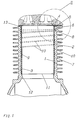
- Fig. 1 shows an axial section through the Cylinder liner 1, which is used in Inside one made of die-cast aluminum, for example manufactured cylinder 2, which in one piece with the crankcase, not shown Single cylinder diesel engine is cast.
- the Cylinder liner 1 is compared to that well-known replacement barrel liners from centrifugal casting one by deep drawing from a steel plate manufactured cheap part, which in the trade too a small part of the price of a usual Centrifugal casting rifle is available.
- the Cylinder liner 1 is the tread with it forming cylinder part 3, which has a wall thickness of 0.5 to 1 mm, with a slight sliding fit mounted inside the cylinder wall 7, i.e. it an annular gap 9 of 20 to 40 p is permitted.
- the sleeve has at its cylinder head end 1 a circumferential collar 4, which in a corresponding annular groove in the end face 13 of the Cylinder wall 7 is added.
- the collar 4th interlocking pockets 5 molded for the Entry of a tool for dismantling the Cylinder liner 1 are provided.
- a spiral Lubrication groove 10 in the inner wall of cylinder 2 serves the even distribution of the Lubricating film. Their cross section corresponds approximately a depth of 1 mm and a width of 2 mm.
- the lubrication groove can either already in the Die casting processes are molded or can be incorporated subsequently.
- the slope the spiral lubricating groove 10 is rather small, for example 1:10.
- the cylinder liner ends with its lower edge 11 1 outside down on it subsequent contour of the cylinder bore 12, so that it is possible to get the pistons from below to assemble.
- the collar 4 of the cylinder liner 1 is slightly over the cylinder head side Face 13 of the cylinder wall 7 over, so that about the cylinder head gasket shown in Fig. 2 14 a secure seal is achieved.
- Cylinder liner 1 Due to its thin wall thickness, it fits Cylinder liner 1 possible tolerance deviations slightly circular in symmetry; she also enables slight transverse movements in adaptation to the stroke direction of the piston, the be dampened by the oil film. Through this slight mobility of the cylinder liner their service life is improved so that their value is over 1000 hours of operation. The exchange against a replacement rifle is very easy. The old cylinder liner is (not tools) which are in the pockets 5 Insert under the edge of the collar 4 upwards levered out; the new rifle is without any reworking used. The exchange of the Cylinder liner 1 is therefore also for single-cylinder small diesel engines economically reasonable.
Landscapes
- Engineering & Computer Science (AREA)
- Chemical & Material Sciences (AREA)
- Combustion & Propulsion (AREA)
- Mechanical Engineering (AREA)
- General Engineering & Computer Science (AREA)
- Cylinder Crankcases Of Internal Combustion Engines (AREA)
Description
- Fig. 1
- den oberen teil des Motorblocks mit einem Axialschnitt durch die Zylinderlaufbüchse und
- Fig. 2
- einen Detail II in Fig. 1.
Claims (8)
- Verbrennungsmotor mit einem oder mehreren Zylindern (2), die durch Zylinderlaufbüchsen (1) ausgekleidet sind, welche durch Tiefziehen oder Druckverformen aus Stahl hergestellt sind,
dadurch gekennzeichnet,
daß die Zylinderlaufbüchse (1) mit Schiebesitz in die zugeordnete Zylinderbohrung (12) eingesetzt ist, mit einer Toleranz, welche unter Betriebstemperaturen einen Ringspalt (9) zwischen Büchse (1) und Zylinderwand (7) mit einer Spaltbreite von 20 bis 40 µ gewährleistet und daß der Ringspalt (9) an einen Schmierölkreislauf angeschlossen ist. - Verbrennungsmotor nach Anspruch 1,
dadurch gekennzeichnet,
daß die Innenseite der Zylinderwand (7) mit Schmiernuten (10) versehen ist, derart, daß im Ringspalt (9) ein geschlossener Ölfilm aufrechterhalten ist. - Verbrennungsmotor nach Anspruch 1, wobei die Zylinderlaufbüchse (1) zylinderkopfseitig einen Bund (4) aufweist, der in einer Ringnut in der Stirnseite (13) der Zylinderwand (7) aufgenommen ist,
dadurch gekennzeichnet,
daß der Bund (4) axial geringfügig über die Stirnseite (13) vorspringt zwecks Schaffung einer dichten Verbindung mit der Zylinderkopfdichtung (14). - Verbrennungsmotor nach Anspruch 3,
dadurch gekennzeichnet,
daß die Dicke des Bunds (4) derart ist, daß er die Zylinderkopfdichtung (14) ersetzt. - Verbrennungsmotor nach Anspruch 3,
dadurch gekennzeichnet,
daß in die Stirnseite (13) der Zylinderwand (7) den Bund (4) untergreifende Taschen (5) eingeformt sind für den Eintritt eines Werkzeugs zur Demontage der Zylinderlaufbüchse (1). - Verbrennungsmotor nach Anspruch 1,
dadurch gekennzeichnet,
daß die Zylinderlaufbüchse (1) eine Lauffläche mit einer Rauhigkeit aufweist, die zur Ausbildung von Öltaschen hinreichend ist. - Verbrennungsmotor nach Anspruch 6,
dadurch gekennzeichnet,
daß die Lauffläche einer Oberflächenbehandlung unterzogen ist, z.B. durch Nitrieren, Verchromen oder Honen. - Verbrennungsmotor nach Anspruch 1,
dadurch gekennzeichnet,
daß die Wandstärke des Zylinderteils (3) der Zylinderlaufbüchse (1) 0,5 bis 1 mm beträgt.
Applications Claiming Priority (3)
| Application Number | Priority Date | Filing Date | Title |
|---|---|---|---|
| DE4436969A DE4436969C2 (de) | 1994-10-15 | 1994-10-15 | Zylinderlaufbüchse |
| DE4436969 | 1994-10-15 | ||
| PCT/EP1995/004002 WO1996012100A1 (de) | 1994-10-15 | 1995-10-11 | Zylinderlaufbüchse |
Publications (2)
| Publication Number | Publication Date |
|---|---|
| EP0786048A1 EP0786048A1 (de) | 1997-07-30 |
| EP0786048B1 true EP0786048B1 (de) | 1998-06-10 |
Family
ID=6530913
Family Applications (1)
| Application Number | Title | Priority Date | Filing Date |
|---|---|---|---|
| EP95936470A Expired - Lifetime EP0786048B1 (de) | 1994-10-15 | 1995-10-11 | Zylinderlaufbüchse |
Country Status (5)
| Country | Link |
|---|---|
| US (1) | US5887558A (de) |
| EP (1) | EP0786048B1 (de) |
| JP (1) | JP3723212B2 (de) |
| DE (2) | DE4436969C2 (de) |
| WO (1) | WO1996012100A1 (de) |
Families Citing this family (17)
| Publication number | Priority date | Publication date | Assignee | Title |
|---|---|---|---|---|
| DE19818589C2 (de) * | 1998-04-25 | 2000-04-20 | Daimler Chrysler Ag | Brennkraftmaschine |
| US6253724B1 (en) * | 1999-12-06 | 2001-07-03 | Samyoung Machinery Co., Ltd. | Cylinder liner with oil pocket |
| ATE306633T1 (de) * | 2001-03-23 | 2005-10-15 | Ibargueengoitia Juan Retolaza | Dünnwandige zylinderbüchse aus leichtmetall für brennkraftmaschine |
| KR100412470B1 (ko) * | 2001-04-30 | 2003-12-31 | 현대자동차주식회사 | 차량용 실린더 라이너 |
| JP2004098147A (ja) * | 2002-09-11 | 2004-04-02 | Honda Motor Co Ltd | スリーブ付きシリンダブロックの製造方法 |
| US7000584B1 (en) * | 2004-03-04 | 2006-02-21 | Brunswick Corporation | Thermally insulated cylinder liner |
| US7726273B2 (en) * | 2004-03-15 | 2010-06-01 | Federal-Mogul World Wide, Inc. | High strength steel cylinder liner for diesel engine |
| US7650710B1 (en) | 2004-06-03 | 2010-01-26 | The United States Of America As Represented By The Secretary Of The Army | Article with enhanced resistance to thermochemical erosion, and method for its manufacture |
| US7191558B1 (en) | 2004-11-10 | 2007-03-20 | The United States Of America As Represented By The Secretary Of The Army | Dynamic process for enhancing the wear resistance of ferrous articles |
| US7559298B2 (en) * | 2006-04-18 | 2009-07-14 | Cleeves Engines Inc. | Internal combustion engine |
| EP2135694A4 (de) * | 2007-03-15 | 2010-08-18 | Honda Motor Co Ltd | Hohlglied, zylinderhülse und herstellungsverfahren dafür |
| US20090172943A1 (en) * | 2008-01-07 | 2009-07-09 | August Jameson Rolling | Process for finishing internal combustion engine cylinders using cold working |
| FI20106227A7 (fi) * | 2010-11-22 | 2012-05-23 | Waertsilae Finland Oy | Moottorilohkojärjestely ja menetelmä kitkakorroosion ehkäisemiseksi |
| DK178682B1 (en) * | 2015-04-15 | 2016-11-07 | Man Diesel & Turbo Filial Af Man Diesel & Turbo Se Tyskland | A large turbocharged self-igniting two-stroke internal combustion engine and a sealing ring therefore |
| EP3577329A1 (de) * | 2017-03-22 | 2019-12-11 | Achates Power, Inc. | Zylinderbohrflächenstrukturen für einen gegenkolbenmotor |
| CN113167190B (zh) * | 2018-12-19 | 2024-07-30 | 卡明斯公司 | 用于减少衬套变形的独特缸体肋几何形状 |
| US20220106923A1 (en) * | 2020-10-07 | 2022-04-07 | Caterpillar Inc. | Cylinder liner |
Family Cites Families (12)
| Publication number | Priority date | Publication date | Assignee | Title |
|---|---|---|---|---|
| US2279671A (en) * | 1939-03-27 | 1942-04-14 | Ford Motor Co | Cylinder liner |
| US2674782A (en) * | 1951-06-20 | 1954-04-13 | Robert E Surtees | Method of making oil retainer sleeves |
| DE1525484B2 (de) * | 1966-02-02 | 1970-03-19 | Maschinenfabrik Augsburg- Nürnberg AG ZwexKniederl. Nürnberg, 85OO Nürnberg | Auswechselbare Laufbüchse für den Zylinder einer Kolbenmaschine |
| DE1955805A1 (de) * | 1969-11-06 | 1971-05-19 | Maschf Augsburg Nuernberg Ag | Zylinder mit trockener Zylinderlaufbuechse |
| US3792518A (en) * | 1972-05-26 | 1974-02-19 | Cross Mfg Co | Cylinders for internal combustion engines, pumps or the like |
| JPS59183054A (ja) * | 1983-03-24 | 1984-10-18 | ザツクス・ジステムテヒニ−ク・ゲゼルシヤフト・ミツト・ベシユレンクテル・ハフツング | 内燃機関用のシリンダユニツト及びその製造方法 |
| DE3407904A1 (de) * | 1983-03-24 | 1984-09-27 | Sachs Systemtechnik Gmbh, 8720 Schweinfurt | Zylinderbaugruppe fuer eine zylinder-kolben-brennkraftmaschine und verfahren zu deren herstellung |
| JPS60178958A (ja) * | 1984-02-24 | 1985-09-12 | Yamaha Motor Co Ltd | 2サイクルエンジン用シリンダスリ−ブの製造方法 |
| DE4029427A1 (de) * | 1989-09-27 | 1991-04-04 | Volkswagen Ag | Zylinder fuer eine fluessigkeitsgekuehlte, schmieroelbehaelter aufweisende hubkolben-brennkraftmaschine |
| US5477820A (en) * | 1994-09-29 | 1995-12-26 | Ford Motor Company | Thermal management system for heat engine components |
| JP2741177B2 (ja) * | 1994-12-22 | 1998-04-15 | 帝国ピストンリング株式会社 | 内燃機関用乾式ライナ |
| US5570668A (en) * | 1995-12-27 | 1996-11-05 | Hsu; Hsin-I | Lubricating device of an engine cylinder |
-
1994
- 1994-10-15 DE DE4436969A patent/DE4436969C2/de not_active Expired - Fee Related
-
1995
- 1995-10-11 EP EP95936470A patent/EP0786048B1/de not_active Expired - Lifetime
- 1995-10-11 WO PCT/EP1995/004002 patent/WO1996012100A1/de not_active Ceased
- 1995-10-11 DE DE59502537T patent/DE59502537D1/de not_active Expired - Lifetime
- 1995-10-11 JP JP51292596A patent/JP3723212B2/ja not_active Expired - Lifetime
-
1997
- 1997-04-14 US US08/843,172 patent/US5887558A/en not_active Expired - Fee Related
Also Published As
| Publication number | Publication date |
|---|---|
| EP0786048A1 (de) | 1997-07-30 |
| US5887558A (en) | 1999-03-30 |
| DE59502537D1 (de) | 1998-07-16 |
| WO1996012100A1 (de) | 1996-04-25 |
| JP3723212B2 (ja) | 2005-12-07 |
| DE4436969A1 (de) | 1996-05-09 |
| JPH10507506A (ja) | 1998-07-21 |
| DE4436969C2 (de) | 1996-08-22 |
Similar Documents
| Publication | Publication Date | Title |
|---|---|---|
| DE4436969C2 (de) | Zylinderlaufbüchse | |
| DE2501605C2 (de) | Gehäuse für eine Brennkraftmaschine | |
| EP2808526B1 (de) | Zylinder einer Hubkolbenmaschine sowie Hubkolbenmaschine | |
| DE4323159C1 (de) | Zweitakt-Brennkraftmaschine | |
| DE3032253A1 (de) | Verbrennungsmotor | |
| DE102011085476A1 (de) | Funktionsoptimierte Gestaltung einer Zylinderlaufbuchse | |
| DE69416230T2 (de) | Brennkraftmaschine | |
| DE19652049C1 (de) | Brennkraftmaschine und Verfahren zu deren Herstellung | |
| EP3310509B1 (de) | Hubkolben-verbrennungskraftmaschine und verfahren zum herstellen einer hubkolben-verbrennungskraftmaschine | |
| EP2738377B1 (de) | Verfahren zur Herstellung eines Zylinderkurbelgehäuses | |
| DE102015007932A1 (de) | Zylinderlaufbuchse mit einer glattgewalzten Ausnehmung | |
| DE60006079T2 (de) | Freikolbenbrennkraftmaschine mit kolbenkopf und radial bewegbare kappe | |
| DE1526462C3 (de) | Zweltakt-Brennkraftmaschine | |
| DE112004002493T5 (de) | Vereinfachte Motorarchitektur und Motorbaugruppe | |
| DE10235911B3 (de) | Gussverbund von Hohlprofilen aus Leichtmetall-Legierung und Verfahren zu seiner Herstellung | |
| DE4336920C2 (de) | Ventiltrieb mit niedriger Reibung | |
| EP1191240B1 (de) | Kreuzkopf-Gleitschuh | |
| DE4015409C1 (de) | ||
| DE4342801C2 (de) | Zylinderkurbelgehäuse | |
| US4342293A (en) | Valve guide and method for making same | |
| DE19547490C1 (de) | Im Druckgußverfahren hergestellter Zylinderkopf einer flüssigkeitsgekühlten Brennkraftmaschine | |
| EP2114590B1 (de) | Verfahren zur herstellung eines zylinderkurbelgehäuses mit mehreren zylinderlaufbuchsen sowie kurze zylinderlaufbuchse mit daran festgelegtem materialstreifen | |
| US4484547A (en) | Valve guide and method for making same | |
| DE102019216820B4 (de) | Flüssigkeitsgekühlte Brennkraftmaschine mit mindestens einem Zylinderrohr | |
| DE19847865A1 (de) | Zylinderlaufbuchse |
Legal Events
| Date | Code | Title | Description |
|---|---|---|---|
| PUAI | Public reference made under article 153(3) epc to a published international application that has entered the european phase |
Free format text: ORIGINAL CODE: 0009012 |
|
| 17P | Request for examination filed |
Effective date: 19970416 |
|
| AK | Designated contracting states |
Kind code of ref document: A1 Designated state(s): DE ES FR GB IT |
|
| GRAG | Despatch of communication of intention to grant |
Free format text: ORIGINAL CODE: EPIDOS AGRA |
|
| ITCL | It: translation for ep claims filed |
Representative=s name: BARZANO'E ZANARDO S.P.A. |
|
| 17Q | First examination report despatched |
Effective date: 19971001 |
|
| GBC | Gb: translation of claims filed (gb section 78(7)/1977) | ||
| GRAG | Despatch of communication of intention to grant |
Free format text: ORIGINAL CODE: EPIDOS AGRA |
|
| GRAH | Despatch of communication of intention to grant a patent |
Free format text: ORIGINAL CODE: EPIDOS IGRA |
|
| GRAH | Despatch of communication of intention to grant a patent |
Free format text: ORIGINAL CODE: EPIDOS IGRA |
|
| GRAA | (expected) grant |
Free format text: ORIGINAL CODE: 0009210 |
|
| AK | Designated contracting states |
Kind code of ref document: B1 Designated state(s): DE ES FR GB IT |
|
| PG25 | Lapsed in a contracting state [announced via postgrant information from national office to epo] |
Ref country code: FR Free format text: LAPSE BECAUSE OF FAILURE TO SUBMIT A TRANSLATION OF THE DESCRIPTION OR TO PAY THE FEE WITHIN THE PRESCRIBED TIME-LIMIT Effective date: 19980610 Ref country code: ES Free format text: THE PATENT HAS BEEN ANNULLED BY A DECISION OF A NATIONAL AUTHORITY Effective date: 19980610 |
|
| REF | Corresponds to: |
Ref document number: 59502537 Country of ref document: DE Date of ref document: 19980716 |
|
| ITF | It: translation for a ep patent filed | ||
| RIN2 | Information on inventor provided after grant (corrected) |
Free format text: KAMPICHLER, GUENTER * EDER, ERICH |
|
| GBT | Gb: translation of ep patent filed (gb section 77(6)(a)/1977) |
Effective date: 19980818 |
|
| EN | Fr: translation not filed | ||
| PLBE | No opposition filed within time limit |
Free format text: ORIGINAL CODE: 0009261 |
|
| STAA | Information on the status of an ep patent application or granted ep patent |
Free format text: STATUS: NO OPPOSITION FILED WITHIN TIME LIMIT |
|
| 26N | No opposition filed | ||
| REG | Reference to a national code |
Ref country code: GB Ref legal event code: IF02 |
|
| PGFP | Annual fee paid to national office [announced via postgrant information from national office to epo] |
Ref country code: GB Payment date: 20061024 Year of fee payment: 12 |
|
| PGFP | Annual fee paid to national office [announced via postgrant information from national office to epo] |
Ref country code: IT Payment date: 20061031 Year of fee payment: 12 |
|
| GBPC | Gb: european patent ceased through non-payment of renewal fee |
Effective date: 20071011 |
|
| PG25 | Lapsed in a contracting state [announced via postgrant information from national office to epo] |
Ref country code: GB Free format text: LAPSE BECAUSE OF NON-PAYMENT OF DUE FEES Effective date: 20071011 |
|
| PG25 | Lapsed in a contracting state [announced via postgrant information from national office to epo] |
Ref country code: IT Free format text: LAPSE BECAUSE OF NON-PAYMENT OF DUE FEES Effective date: 20071011 |
|
| PGFP | Annual fee paid to national office [announced via postgrant information from national office to epo] |
Ref country code: DE Payment date: 20141229 Year of fee payment: 20 |
|
| REG | Reference to a national code |
Ref country code: DE Ref legal event code: R071 Ref document number: 59502537 Country of ref document: DE |