EP0786035B1 - Vorrichtung zum verankern des fundaments eines bauwerks im boden - Google Patents
Vorrichtung zum verankern des fundaments eines bauwerks im boden Download PDFInfo
- Publication number
- EP0786035B1 EP0786035B1 EP95934191A EP95934191A EP0786035B1 EP 0786035 B1 EP0786035 B1 EP 0786035B1 EP 95934191 A EP95934191 A EP 95934191A EP 95934191 A EP95934191 A EP 95934191A EP 0786035 B1 EP0786035 B1 EP 0786035B1
- Authority
- EP
- European Patent Office
- Prior art keywords
- anchor
- axis
- traction
- line
- ground
- Prior art date
- Legal status (The legal status is an assumption and is not a legal conclusion. Google has not performed a legal analysis and makes no representation as to the accuracy of the status listed.)
- Expired - Lifetime
Links
Images


Classifications
-
- E—FIXED CONSTRUCTIONS
- E02—HYDRAULIC ENGINEERING; FOUNDATIONS; SOIL SHIFTING
- E02D—FOUNDATIONS; EXCAVATIONS; EMBANKMENTS; UNDERGROUND OR UNDERWATER STRUCTURES
- E02D5/00—Bulkheads, piles, or other structural elements specially adapted to foundation engineering
- E02D5/74—Means for anchoring structural elements or bulkheads
- E02D5/80—Ground anchors
- E02D5/803—Ground anchors with pivotable anchoring members
-
- E—FIXED CONSTRUCTIONS
- E02—HYDRAULIC ENGINEERING; FOUNDATIONS; SOIL SHIFTING
- E02D—FOUNDATIONS; EXCAVATIONS; EMBANKMENTS; UNDERGROUND OR UNDERWATER STRUCTURES
- E02D2600/00—Miscellaneous
- E02D2600/30—Miscellaneous comprising anchoring details
Definitions
- the present invention relates to a new device anchor of structural foundation in the ground.
- the technical sector of the invention is the field of realization of anchors that we drive into any terrain, either from the surface of an underground gallery or gallery wall or other, by threshing, vibratory driving, launching or other, up to a certain depth or distance from said. surface and then on which by a pulling device which can be a cable, a chain, a strap or other deformable rod provided the connection with the anchor either flexible and / or articulated, a traction is applied from this surface so that said anchor tilts into a position transverse to the direction of traction and that it then allows resist by opposing a maximum surface area of its sails to this pulling and thus immobilizing the pulling up to a certain value of effort of this traction.
- a pulling device which can be a cable, a chain, a strap or other deformable rod provided the connection with the anchor either flexible and / or articulated
- the EP patent application 161 190 published on November 13, 1985 of the I.F.P. has a shutter articulated on the rear of the anchor wing to initiate more quickly block before tilting.
- Such a device does not cannot, however, prevent a significant rise in the anchor during tensioning especially in cases where to facilitate the sinking, a pilot hole was made with an auger: part of the flap is in a vacuum and its stop action is reduced and delayed.
- the flap joints break.
- materials can get caught between the flap and its stop and to prohibit its movement therefore its office. This brings back to the case previous.
- the problem is therefore to be able to make a device anchor, comprising an anchor and a line of traction, and the implementation essentially allows the tilting of the anchor as soon as the desired depth reached to then ensure said anchoring to a given depth and this in any type of terrain; another objective of the invention is also to achieve the insertion of said anchor in said soil by controlling the direction without risk of great deviation.
- the anchoring device comprises a piece of guidance and support relative to the body of the anchor, of said end of the line between said attachment point and its axis of ZZ 'traction, which support piece transmitting an effect to the body of the anchor transverse to the axis, creating a tilting torque when said end is energized by the line tensile along this axis
- said guide piece ensures said offset and is a part of the body of the anchor on which rests on said end of the traction line or cable, fixed said attachment point.
- said guide piece is constituted by a piece rigid which forms the end of the line of traction, which is articulated around said point of attachment and which rests on the body of the anchor by a spring housed therein and which is compressed in threshing position, between the rigid end of said line of traction and said body of the anchor.
- the pull line can be itself fully rigid, and therefore in one piece, articulated directly in the anchor body, around a point of attachment secured to its end such as a pin which can either be offset from the traction axis XX ', the end of the part rigid then bent, be aligned with it.
- said anchor also comprises another fin of protection in front of said guide piece perpendicular to the plane of the front wing and of a height h with respect thereto greater than the offset distance from the axis ZZ 'of said cable traction relative to the front wing of the body of the anchor; of preferably, said fins respectively called protection and tilt, are symmetrical with respect to said sail plane front, identical and both located in front of said piece of guidance.
- one of the great innovations and originalities of the present invention is to define well the connection of the end of the anchor line with the anchor itself following a well position determined whereas so far all the known anchors at contrary included flexible and free connections without guidance nor forced support because we were always looking for the alignment of the line of traction and its point of attachment to the anchor as soon as it is placed under tension: this absolutely does not create a support force voluntary R, transverse to the direction of traction ZZ ', such that shown in particular in Figures 2 and 8 illustrative described below, thus allowing according to the present invention a instant pre-tilting of the anchor, either when power is applied of the traction line, i.e. as soon as the threshing rod is removed, whatever the nature of the terrain.
- the end of the anchor line is always intentionally set in contact by a guide and support piece with the body of the anchor, directly or by an intermediate spring, which part is one of the essential elements of the present invention, whereas in known anchor lines, even articulated and offset by relative to the axis of the anchor, it is only transmitted to the body of the anchor force aligned in the applied direction of tension without causing a transverse force of reaction on the anchor.
- pre-tilt perpendicular to the plane main sail of the anchor, and located on the other side in relation to to the line of traction, allows, in addition to better guidance during sinking the anchor in a given direction, to constitute a almost instant stop heel from the start of the effort traction; this creates a real immediate pre-tilt couple anchor, in combination with the specific line layout anchor according to the invention, as described in one of the modes of embodiment of Figure 2 or Figure 8, and shown in implementation work in Figures 7 and 11 below.
- the tilting moment constituted only by the traction applied to the lever arm formed by the offset of the line of traction relative to the axis of the anchor is not sufficient to ensure said tilting according to the terrain encountered as said before, except waiting for some raising the anchor in its hole until the friction allow to obtain a tilting torque, when the rear of the wing has the good fortune to come to a stop.
- this shift is due to the need to release the penetration axis of the anchor in the soil to let the threshing rods pass, and various solutions have been proposed, like those mentioned in the introduction to ensure really the tipping, proving that the moment of the above forces is considered insufficient, but these solutions have not has produced convincing results to date.
- the existence of the recessed spring in the body of the anchor and bearing on the end of the line anchor allows you to get, when you decide and immediately then, the pre-tilting of said anchor and accompanying the tilting it up to an angle of around 30 °, allowing irreversibly, hooking the back of the airfoil in the ground at a determined and desired height, which is all the more necessary, when we are shallow in the soil, and we want to obtain optimum tensile strength; the movement is then independent of the shape of the anchor and allows give it all the more favorable forms of penetration anchor in the ground.
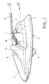
- Figure 1 is an overall perspective view of an example of realization of an anchoring device according to the invention.
- Figure 2 is a longitudinal sectional view of a device according to Figure 1.
- Figure 3 is a simplified view of the same device as that shown in Figure 2.
- Figure 4 is a sectional view along CC 'of the device of the Figure 3.
- Figure 5 is a longitudinal sectional view of a device according to the invention, according to another embodiment.
- Figure 6 is a cross-sectional view along DD 'of Figure 5 device.
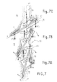
- Figure 7 is a representation of the different phases of tilting during the implementation of a device according to the Figures 1 to 6.
- FIG. 8 is a sectional view longitudinal along VIII / VIII 'of the top view according to the figure 10 and FIG. 9 is a sectional view along line IX / IX 'of FIG. 8.
- Figures 11 and 12 are representations of implementation operation of a device according to FIGS. 8 to 10.
- the structure foundation anchoring device in the ground indeed comprises in a known manner an anchor 1 and a line of traction 8, which is applied along an axis ZZ '.
- the body of the anchor 1 is made up of various elements such as that in particular a profiled front wing 2 to penetrate the ground and which can consist of two bevelled wings their ends and symmetrical on either side of the plane defined by the axes of the traction line ZZ 'and of the direction XX' of anchor penetration: said profiled front wing 2 thus allows the anchoring of the anchor in the ground along said axis XX 'thanks to the thrust transmitted by a threshing element 20 which is pressed from the surface of the ground or the wall of the ground in which one wants to make penetrate said anchor and which is housed along the axis XX 'to the rear of the anchor in a housing 4 provided for this.
- Said body of the anchor 1 also comprises on either side of this housing 4 a rear wing 3 in the extension of the front wing 2 and of sufficient area to allow oppose the traction effect of line 8, in the position anchor, making a stop in the ground and as shown in the Figure 7, after the anchor has entered and after a first step tilting, said stop being represented by the force F'2 on this Figure 7, while the front wing 2 also ensures the other side of the axis ZZ 'a reaction by stop in the following soil force F'3: it is the combination of these two reaction forces in the ground which ensure the balance of the anchor and the restraint of the traction line 8 subjected to the traction force T4 desired after placing the anchor at the given depth.
- the end of one of the ends 18 of the traction line 8 is secured to a point or attachment piece 9 located in the middle of the body of anchor 1, which attachment point 9 must be offset from the ZZ 'axis of traction thereof towards the XX' axis of the body of the anchor 1 for the embodiments of Figures 1 to 7, and even preferably located along said axis to obtain a torque the highest possible tilt, while in the realization of Figures 8 to 12, this offset may be nonexistent or at least less important since the desired tilting torque and necessary is then ensured by the power of the spring 24 put in compression.
- said guide and support piece 7 is part of said body of anchor 1 and on which said base is based end 18 of the pull line, which is then necessarily deformable, such as a cable, which will be cited as reference in the following description of Figures 1 to 7, which end 18 is fixed to said attachment point 9: this piece of guide and support 7 allows the end 18 of the traction line 8 to be guided between said attachment point 9 and the traction axis ZZ ' proper, ensuring said offset and in shape such that said end 18 of the traction cable 8 forms an angle ⁇ of more than 10 ° and less than 90 ° with the axis XX 'of the anchor, and preferably between 60 and 90 °.
- said point or attachment piece 9 consists of a hinge end of in this case cylindrical shape of revolution at least along an axis perpendicular to said axes XX 'and ZZ', fixed and integral with the end 19 of the end 18 of the cable 8 on which it is breeched: said end piece 9 can thus be a cylindrical part or a spherical part: it can also be a fastener in the body of the anchor; the room constituting the end piece 9 may include a hollow appendage in which pass the end 18 of the cable 8: it is this appendage which then comes resting against the guide piece 7 of the anchor body.
- Said end piece 9 is housed and articulated in a housing 10 in the body of the anchor in which it can rotate at least along the perpendicular axis to said axes XX 'and ZZ' and communicates with an orifice 20 in the form of trunk through which said end 18 of the cable passes.
- this accommodation is located in front of the surface center of the entire wing 2, 3 of said anchor.
- Said body of the anchor 1 may also include a fin 5 of protection in front of said support piece 5 to protect it and the cable when sinking into the ground, perpendicular to the plane of the front airfoil 2 and a height h relative to the latter, greater than the offset distance d of the axis ZZ 'of said cable traction 8, as well as a fin 6 located on the other side of the plane of front wing 2 with respect to this first fin 5.
- the two so-called fins 5 and 6 are preferably symmetrical by compared to sail plan 2 and identical in order to balance the forces when hitting the anchor and so and thanks to their combination with the front wing 2, make it possible to guarantee the direction of threshing.
- said fin 5 or rib upper which is profiled on the front to allow penetration in the ground cuts it and protects the cable 8, while the rib lower or fin 6, also profiled on the front of the same way, cuts the ground like the upper rib, and moreover, by its heel effect 16, made tilting stop as illustrated on the Figure 7.
- Figure 3 is therefore a representation of the device according to the Figure 2, in section AA 'according to Figure 4, while the latter is a section along CC 'of the same device in Figure 3: the housing 10 end piece 9 and the latter are cylindrical in shape.
- the end 19 of end 18 of cable 8 can be directly breeched in a housing 17 of the body of the anchor 1 and said support piece 7 is extends beyond the support area of the end of the cable 8 at 90 ° with axis XX 'up to said housing 17 to constitute therewith said attachment point 9.
- the first step is that of the immediate, immediate and irreversible, when tensioning the cable or line anchor 8 subjected to the T2 force, thanks to the composition of the parallelogram of action and reaction forces as described according to Figure 2.
- This force R is therefore of course the most important at the start of rotation during this pre-tilt step in which this force, if we take a sufficiently large angle ⁇ , causes a tilting torque, due to the distance of this resultant R to rotation point G, large enough to ensure the tilting in the field, whatever the nature of it.
- the end of the tilting illustrated for example in position 14 is continues by balancing the reaction forces of the ground F'3 and F'2, which also compensate for the tension force T4 applied to the cable 8, relative to the position of the pull point of it, which is preferably in front of the surface center of gravity, until you have a stability of this balance: the two couples generated by these two reaction forces in the soil to compensate and therefore cancel each other out to obtain this balance at the desired final angle of the axis XX 'by relative to the initial threshing axis PP 'or traction ZZ' of the cable 8.
- the cable 8 used in this description can be replaced by any deformable and / or flexible line allowing the transmission of tensile forces, such as a chain, belt or any other device such as a deformable rod.
- Figures 8 to 12 show another embodiment of the invention, the main application of which is anchoring at low depth up to about one meter, and in which said piece of guide and support 7 is not part of the anchor body as previously, but of the traction line 8: it is constituted by a rigid part forming the end 18 of the traction line 8, is supported by a spring 24 on the body 1 of the anchor and is articulated around point 9.
- the actual traction line 8 can be in one piece to the ground surface, understand end 18 and be made in one piece up to and including the joint and attachment point 9; the line of traction up to surface can also consist of a deformable line as in Figures 1 to 7, and be fixed near the anchor 1 on the other end, relative to the attachment point 9, of said part end 18 which is then only rigid.
- the elements already described above such as the main body 1 of the anchor, comprising a bulge forming a fin, in which is located the joint and anchor point 9, and a fin forming spur-stop 6 on the other side;
- the rear part of the body 1 of the anchor has a bore 4 for guiding the end of the threshing rod 20, the rear 22 of the body 1 serving inter alia anvil to said threshing rod as shown in Figure 11.
- the sail of the anchor is in its rear part 3 of constant section, and in its front part 2 of tapered section, for penetration into the ground 11 with two lateral heels 23, favoring the attachment in the ground during traction T on the anchor line 8; the mode of implementation shown in Figures 11 and 12, corresponds to same phases described as in the representation of FIGS. 7 to which we will refer, in particular for the pre-tilt positions 12 and 13 of Figures 7a and 7b.
- Such an anchor is designed to offer less resistance to soil penetration, although pilot holes can be made beforehand, these shapes being tapered in arrowheads, and all the wing elements connecting to the actual body of the anchor by large radii of curvature of form.
- a housing is practiced 10 in which the end attachment point 9 of the line is embedded anchor 8, such as by a tenon joint or along an axis or a cylindrical journal forming part of said anchor line; which housing 10 opens with a light 20 on the face which is can call dorsal of the anchor, for passage and rotation relative to the anchor, about 90 ° for example, from the rigid piece 7 at the end 18 of the anchor line 8 between the threshing position and the final anchoring position; this anchor line can be put on during its assembly by the ventral side of the anchor where said housing 10 opens.
- the articulation 9 is located slightly in front of the center surface of anchor 1, and another bore 25 located on the rear of this articulation 9 contains the spring 24 and can communicate with that of the threshing rod: this spring 24 gives an impulse of pre-tilting and therefore attachment of the anchor when it is set place when removing the threshing rod 20.
- this spring 24 gives an impulse of pre-tilting and therefore attachment of the anchor when it is set place when removing the threshing rod 20.
- a lug or any means of support can be integral with the threshing rod 20 to keep the end 18 against it until it is withdrawn.
- the spring 24 is of the sausage and works on compression: it is well protected from the environment around 11 during threshing because it can be fully accommodated in the bore 25, which is then closed by the rigid part 7, preventing any ingress of gravel or other particles from the ground which could then hinder its expansion.
- the bent bent shape of the end portion 18 of the anchor line makes it possible to make up for the traction offset ZZ 'by relative to hinge axis 9: this offset can be useful for embed the pin 9 in the anchor body without having to overdo it magnify it, but may not exist due to the existence of the spring 24 which gives the tilting torque by its force of reaction R.
- a rigid traction line 8 arranged and articulated along the threshing axis XX ': either then it is the traction line 8 itself which ensures threshing, or the threshing rod 20 is hollow and surrounds the traction line 8; the spring 24 would be located in a bore offset from the axis XX '.
Landscapes
- Engineering & Computer Science (AREA)
- Structural Engineering (AREA)
- Life Sciences & Earth Sciences (AREA)
- General Life Sciences & Earth Sciences (AREA)
- Mining & Mineral Resources (AREA)
- Paleontology (AREA)
- Civil Engineering (AREA)
- General Engineering & Computer Science (AREA)
- Piles And Underground Anchors (AREA)
- Vehicle Body Suspensions (AREA)
- Foundations (AREA)
- Joining Of Building Structures In Genera (AREA)
- Reinforcement Elements For Buildings (AREA)
Claims (10)
- Vorrichtung zum Verankern des Fundaments eines Bauwerks im Boden, mit einem Anker (1) und einer Zugleine (8) mit einer Achse (ZZ'), bei der das Endstück (19) des einen Endes (18) fest mit einem Angriffspunkt (9) oder Angriffsteil verbunden ist, der bzw. das auf dem Körper des Ankers (1) befestigt ist, wobei dieser Körper eine vordere, profilierte Ausbuchtung (2) aufweist, um längs seiner Achse (XX') in den Boden einzudringen, und eine hintere Ausbuchtung (3), um sich der Zugwirkung der genannten Leine (8) dadurch zu widersetzen, daß sie im Boden ein Widerlager bildet, nachdem der Anker dort eingedrungen ist und verschwenkt wurde, dadurch gekennzeichnet, daß sie ein Führungs- und Anlageteil (7) für das genannte Ende (18) der genannten Zugleine (8) aufweist, wobei das Anlageteil (7), das zwischen dem Angriffspunkt (9) und der Zugachse (ZZ') angeordnet ist, auf den Körper des Ankers (1) eine Kraft quer zur Achse (ZZ') überträgt, die ein Schwenkmoment erzeugt, wenn das genannte Ende (18) durch die Zugleine (8) in dieser Achse (ZZ') unter Zugspannung gesetzt wird, und daß der Körper des Ankers (1) eine Flosse (6) aufweist, die auf der anderen Seite der Ebene der vorderen Ausbuchtung (2) in Bezug auf das Führungsteil (7) gelegen ist und ein hinteres Ende (16) aufweist, das sich im Boden anlegt und sperrt, sobald die Zugleine (8) in der Achse (ZZ') unter Zugspannung gesetzt ist und danach trachtet, den Anker wieder heraustreten zu lassen.
- Vorrichtung nach Anspruch 1, dadurch gekennzeichnet, daß das Führungsteil (7) von einem steifen Teil gebildet ist, das das Ende (18) der Zugleine (8) bildet, das um den Punkt (9) gelenkig angeordnet ist und sich auf dem Körper (1) des Ankers durch eine Feder (24) abstützt.
- Vorrichtung nach Anspruch 2, dadurch gekennzeichnet, daß das genannte steife Teil (7) gebogen ist und daß sein Ende (18) durch einen Drehzapfen endet, der den genannten Angriffspunkt (9) der Zugleine (8) bildet.
- Verankerungsvorrichtung nach Anspruch 1, dadurch gekennzeichnet, daß der Angriffspunkt (9) der Zugleine in Bezug auf die Achse (ZZ') ihrer Zugspannung zur Achse (XX') des Körpers des Ankers (1) hin versetzt ist, und daß das Führungsteil (7) die genannte Versetzung sicherstellt und ein Abschnitt des Körpers (1) des Ankers ist, auf dem sich das genannte Ende (18) der Zugleine (8), das am genannten Punkt (9) befestigt ist, abstützt, die verformbar ist.
- Vorrichtung nach irgendeinem der Ansprüche 1 bis 4, dadurch gekennzeichnet, daß der genannte Angriffspunkt (9) von einem Ansatz gebildet ist, der zylindrisch ist, mindestens entsprechend einer Achse senkrecht zu den genannten Achsen (XX') und (ZZ') einen Rotationskörper bildet, festgelegt ist, fest mit dem Endstück (19) des genannten Endes (18) der Zugleine (8) verbunden ist und in einem Sitz (10) schwenkbar gelagert ist, der im Körper des Ankers ausgebildet ist, in dem er sich drehen kann.
- Vorrichtung nach Anspruch 4, dadurch gekennzeichnet, daß das Endstück (19) des genannten Endes der Leine (8) unmittelbar in einem Sitz (17) des Körpers des Ankers (1) eingesetzt ist und das genannte Führungs- und Anlagestück (7) über die Zone der Anlage des Endes (18) der Leine (8) hinaus unter 90° zur Achse (XX') bis zum genannten Sitz (17) verlängert ist, um zusammen mit diesem den genannten Angriffspunkt (9) zu bilden.
- Ankervorrichtung nach irgendeinem der Ansprüche 3 bis 6, dadurch gekennzeichnet, daß der genannte Angriffspunkt (9) in der Achse (XX') des Körpers des Ankers gelegen ist.
- Vorrichtung nach irgendeinem der Ansprüche 3 bis 7, dadurch gekennzeichnet, daß der Winkel (β) zwischen dem Ende (18) der Zugleine (8) und der Achse (XX') des Ankers (1) zwischen 10 und 90° beträgt.
- Vorrichtung nach irgendeinem der Ansprüche 1 bis 8, dadurch gekennzeichnet, daß der genannte Anker (1) eine Schutzflosse (5) vor dem genannten Führungsteil (7) senkrecht zur Ebene der vorderen Ausbuchtung (2) und mit einer Höhe h in Bezug auf diese aufweist, die größer ist als die Strecke der Versetzung der Achse (ZZ') der genannten Zugleine (8).
- Vorrichtung nach Anspruch 9, dadurch gekennzeichnet, daß die beiden Flossen (5, 6) in Bezug auf die genannte Ebene der vorderen Ausbuchtung (2) symmetrisch sind, identisch sind und alle beide vor dem genannten Führungsteil (7) gelegen sind.
Applications Claiming Priority (3)
| Application Number | Priority Date | Filing Date | Title |
|---|---|---|---|
| FR9412563A FR2725739A1 (fr) | 1994-10-14 | 1994-10-14 | Dispositif d'ancrage de fondation de structure dans le sol |
| FR9412563 | 1994-10-14 | ||
| PCT/FR1995/001316 WO1996012068A1 (fr) | 1994-10-14 | 1995-10-09 | Dispositif d'ancrage de fondation de structure dans le sol |
Publications (2)
| Publication Number | Publication Date |
|---|---|
| EP0786035A1 EP0786035A1 (de) | 1997-07-30 |
| EP0786035B1 true EP0786035B1 (de) | 1998-08-26 |
Family
ID=9468058
Family Applications (1)
| Application Number | Title | Priority Date | Filing Date |
|---|---|---|---|
| EP95934191A Expired - Lifetime EP0786035B1 (de) | 1994-10-14 | 1995-10-09 | Vorrichtung zum verankern des fundaments eines bauwerks im boden |
Country Status (12)
| Country | Link |
|---|---|
| US (1) | US5815993A (de) |
| EP (1) | EP0786035B1 (de) |
| JP (1) | JPH10512634A (de) |
| KR (1) | KR970706439A (de) |
| CN (1) | CN1160427A (de) |
| AT (1) | ATE170247T1 (de) |
| AU (1) | AU699700B2 (de) |
| DE (1) | DE69504363T2 (de) |
| ES (1) | ES2122681T3 (de) |
| FR (1) | FR2725739A1 (de) |
| MA (1) | MA23693A1 (de) |
| WO (1) | WO1996012068A1 (de) |
Families Citing this family (9)
| Publication number | Priority date | Publication date | Assignee | Title |
|---|---|---|---|---|
| GB9322640D0 (en) * | 1993-11-03 | 1993-12-22 | Platipus Anchors Ltd | Improvements in ground anchors |
| FR2764618B1 (fr) | 1997-06-13 | 1999-09-03 | Tecnivalor | Procede et dispositif d'embase dans le sol s'opposant aux efforts lateraux et au glissement |
| SE524884C2 (sv) * | 2002-12-03 | 2004-10-19 | Fredrik Lagercrantz | Fästelement |
| US20070094951A1 (en) * | 2005-09-27 | 2007-05-03 | Accuplastics, Inc. | Taco Shell Earth Anchor |
| US7789594B2 (en) * | 2007-08-10 | 2010-09-07 | Foresight Products, Llc | Ground anchor |
| NL2011788C2 (en) * | 2013-11-12 | 2015-05-13 | J F Karsten Beheer B V | Method and apparatus for stabilising a dike. |
| JP6521512B2 (ja) * | 2015-02-25 | 2019-05-29 | 極東産機株式会社 | 紐状部材による構造体の固定装置 |
| US10557521B2 (en) * | 2018-05-16 | 2020-02-11 | The North Face Apparel Corp. | Stake with cord lock |
| WO2022232144A1 (en) * | 2021-04-26 | 2022-11-03 | Western Green, Llc | Ground anchor assembly including high-load ground anchor and method of using same |
Family Cites Families (5)
| Publication number | Priority date | Publication date | Assignee | Title |
|---|---|---|---|---|
| US2841256A (en) * | 1954-12-24 | 1958-07-01 | Jr Merton L Clevett | Ground anchor |
| US3139163A (en) * | 1960-12-27 | 1964-06-30 | Augustine C Haller | Ground anchor |
| GB8402362D0 (en) * | 1984-01-30 | 1984-02-29 | Alsop Peter | Anchoring devices |
| US4611446A (en) * | 1985-12-26 | 1986-09-16 | Beavers Allan E | Cable anchoring device |
| FR2678010B1 (fr) * | 1991-06-21 | 1998-06-12 | Electricite De France | Ancre de fondation a volet tournant. |
-
1994
- 1994-10-14 FR FR9412563A patent/FR2725739A1/fr active Granted
-
1995
- 1995-10-09 AU AU36578/95A patent/AU699700B2/en not_active Ceased
- 1995-10-09 CN CN95195647A patent/CN1160427A/zh active Pending
- 1995-10-09 AT AT95934191T patent/ATE170247T1/de not_active IP Right Cessation
- 1995-10-09 EP EP95934191A patent/EP0786035B1/de not_active Expired - Lifetime
- 1995-10-09 WO PCT/FR1995/001316 patent/WO1996012068A1/fr not_active Application Discontinuation
- 1995-10-09 DE DE69504363T patent/DE69504363T2/de not_active Expired - Lifetime
- 1995-10-09 US US08/809,887 patent/US5815993A/en not_active Expired - Fee Related
- 1995-10-09 KR KR1019970702378A patent/KR970706439A/ko not_active Application Discontinuation
- 1995-10-09 ES ES95934191T patent/ES2122681T3/es not_active Expired - Lifetime
- 1995-10-09 JP JP8512978A patent/JPH10512634A/ja active Pending
- 1995-10-12 MA MA24038A patent/MA23693A1/fr unknown
Also Published As
| Publication number | Publication date |
|---|---|
| MA23693A1 (fr) | 1996-07-01 |
| CN1160427A (zh) | 1997-09-24 |
| WO1996012068A1 (fr) | 1996-04-25 |
| FR2725739A1 (fr) | 1996-04-19 |
| FR2725739B1 (de) | 1997-02-21 |
| AU3657895A (en) | 1996-05-06 |
| EP0786035A1 (de) | 1997-07-30 |
| JPH10512634A (ja) | 1998-12-02 |
| DE69504363D1 (de) | 1998-10-01 |
| DE69504363T2 (de) | 1999-03-25 |
| KR970706439A (ko) | 1997-11-03 |
| ATE170247T1 (de) | 1998-09-15 |
| ES2122681T3 (es) | 1998-12-16 |
| US5815993A (en) | 1998-10-06 |
| AU699700B2 (en) | 1998-12-10 |
Similar Documents
| Publication | Publication Date | Title |
|---|---|---|
| CA1335475C (fr) | Piece d'ancrage, notamment pour beton | |
| EP0161190B1 (de) | Verankerungsvorrichtung mit angelinktem geknicktem Teil | |
| EP0786035B1 (de) | Vorrichtung zum verankern des fundaments eines bauwerks im boden | |
| EP0874941B1 (de) | Automatisches schützentor für hydraulisches werk sowie flussschwelle, dammwasser ablass oder schutz deich | |
| LU83420A1 (fr) | Tete d'ancrage | |
| EP1846619A1 (de) | Einem steinbrecher zuzuordnende rammvorrichtung | |
| EP0434819B1 (de) | Hebe- und aufrichtanker, insbesondere für betonplatten | |
| WO1983004424A1 (fr) | Outil d'enfoncement et de guidage de chevilles de fixation pour piquets | |
| FR2945300A1 (fr) | Barriere | |
| FR2957615A1 (fr) | Barriere a liaison fracturable | |
| WO2013114055A1 (fr) | Pieu d'ancrage | |
| CA2202392A1 (fr) | Dispositif d'ancrage de fondation de structure dans le sol | |
| BE1008652A6 (fr) | Pylone pourvu d'un manchon conique interieur. | |
| EP0024221B1 (de) | Schiffsanker, insbesondere für Grossschiffe | |
| FR3098534A1 (fr) | Ancre de levage pour mur à coffrage intégré et mur à coffrage intégré comportant ladite ancre de levage | |
| FR2678010A1 (fr) | Ancre de fondation a volet tournant. | |
| FR2765252A1 (fr) | Glissieres de securite routiere en bois fixees par des elements ecarteurs sur des poteaux immobilises dans le sol | |
| FR3074202A1 (fr) | Amarre a bascule a deux composants assembles mecaniquement | |
| FR2901292A1 (fr) | Dispositif d'ancrage a bascule | |
| FR3074201A1 (fr) | Amarre a bascule perfectionnee | |
| WO1986005834A1 (fr) | Cheville a fourreau rapporte destinee a la fixation dans le sol de poteaux ou piquets | |
| WO1979001017A1 (fr) | Nouveau systeme d'ancrage | |
| FR2690410A1 (fr) | Ancre de marine du type plate et démontable. | |
| CH631788A5 (fr) | Dispositif d'attache a elements. | |
| FR2866360A1 (fr) | Ancre permettant de fixer au sol un tirant ou analogue |
Legal Events
| Date | Code | Title | Description |
|---|---|---|---|
| PUAI | Public reference made under article 153(3) epc to a published international application that has entered the european phase |
Free format text: ORIGINAL CODE: 0009012 |
|
| 17P | Request for examination filed |
Effective date: 19970411 |
|
| AK | Designated contracting states |
Kind code of ref document: A1 Designated state(s): AT BE CH DE DK ES FR GB GR IE IT LI LU MC NL PT SE |
|
| RIN1 | Information on inventor provided before grant (corrected) |
Inventor name: PASQUALINI, CHARLES Inventor name: LAUGEOIS, RENE Inventor name: CASTOLA, CHARLES-ALAIN |
|
| GRAG | Despatch of communication of intention to grant |
Free format text: ORIGINAL CODE: EPIDOS AGRA |
|
| 17Q | First examination report despatched |
Effective date: 19971210 |
|
| GRAG | Despatch of communication of intention to grant |
Free format text: ORIGINAL CODE: EPIDOS AGRA |
|
| GRAH | Despatch of communication of intention to grant a patent |
Free format text: ORIGINAL CODE: EPIDOS IGRA |
|
| GRAH | Despatch of communication of intention to grant a patent |
Free format text: ORIGINAL CODE: EPIDOS IGRA |
|
| GRAA | (expected) grant |
Free format text: ORIGINAL CODE: 0009210 |
|
| AK | Designated contracting states |
Kind code of ref document: B1 Designated state(s): AT BE CH DE DK ES FR GB GR IE IT LI LU MC NL PT SE |
|
| PG25 | Lapsed in a contracting state [announced via postgrant information from national office to epo] |
Ref country code: GR Free format text: LAPSE BECAUSE OF FAILURE TO SUBMIT A TRANSLATION OF THE DESCRIPTION OR TO PAY THE FEE WITHIN THE PRESCRIBED TIME-LIMIT Effective date: 19980826 |
|
| REF | Corresponds to: |
Ref document number: 170247 Country of ref document: AT Date of ref document: 19980915 Kind code of ref document: T |
|
| REG | Reference to a national code |
Ref country code: CH Ref legal event code: EP |
|
| REF | Corresponds to: |
Ref document number: 69504363 Country of ref document: DE Date of ref document: 19981001 |
|
| GBT | Gb: translation of ep patent filed (gb section 77(6)(a)/1977) |
Effective date: 19980923 |
|
| REG | Reference to a national code |
Ref country code: CH Ref legal event code: NV Representative=s name: BOVARD AG PATENTANWAELTE |
|
| REG | Reference to a national code |
Ref country code: IE Ref legal event code: FG4D Free format text: FRENCH |
|
| PG25 | Lapsed in a contracting state [announced via postgrant information from national office to epo] |
Ref country code: SE Free format text: LAPSE BECAUSE OF FAILURE TO SUBMIT A TRANSLATION OF THE DESCRIPTION OR TO PAY THE FEE WITHIN THE PRESCRIBED TIME-LIMIT Effective date: 19981126 Ref country code: DK Free format text: LAPSE BECAUSE OF FAILURE TO SUBMIT A TRANSLATION OF THE DESCRIPTION OR TO PAY THE FEE WITHIN THE PRESCRIBED TIME-LIMIT Effective date: 19981126 |
|
| REG | Reference to a national code |
Ref country code: ES Ref legal event code: FG2A Ref document number: 2122681 Country of ref document: ES Kind code of ref document: T3 |
|
| REG | Reference to a national code |
Ref country code: PT Ref legal event code: SC4A Free format text: AVAILABILITY OF NATIONAL TRANSLATION Effective date: 19981026 |
|
| PLBE | No opposition filed within time limit |
Free format text: ORIGINAL CODE: 0009261 |
|
| STAA | Information on the status of an ep patent application or granted ep patent |
Free format text: STATUS: NO OPPOSITION FILED WITHIN TIME LIMIT |
|
| 26N | No opposition filed | ||
| REG | Reference to a national code |
Ref country code: GB Ref legal event code: IF02 |
|
| PGFP | Annual fee paid to national office [announced via postgrant information from national office to epo] |
Ref country code: MC Payment date: 20030917 Year of fee payment: 9 |
|
| PGFP | Annual fee paid to national office [announced via postgrant information from national office to epo] |
Ref country code: NL Payment date: 20030918 Year of fee payment: 9 Ref country code: LU Payment date: 20030918 Year of fee payment: 9 |
|
| PGFP | Annual fee paid to national office [announced via postgrant information from national office to epo] |
Ref country code: IE Payment date: 20030924 Year of fee payment: 9 |
|
| PGFP | Annual fee paid to national office [announced via postgrant information from national office to epo] |
Ref country code: CH Payment date: 20031013 Year of fee payment: 9 |
|
| REG | Reference to a national code |
Ref country code: PT Ref legal event code: NF4A Free format text: RESTITUTIO IN INTEGRUM Effective date: 20040212 |
|
| PG25 | Lapsed in a contracting state [announced via postgrant information from national office to epo] |
Ref country code: LU Free format text: LAPSE BECAUSE OF NON-PAYMENT OF DUE FEES Effective date: 20041009 |
|
| PG25 | Lapsed in a contracting state [announced via postgrant information from national office to epo] |
Ref country code: IE Free format text: LAPSE BECAUSE OF NON-PAYMENT OF DUE FEES Effective date: 20041011 |
|
| PG25 | Lapsed in a contracting state [announced via postgrant information from national office to epo] |
Ref country code: MC Free format text: LAPSE BECAUSE OF NON-PAYMENT OF DUE FEES Effective date: 20041031 Ref country code: LI Free format text: LAPSE BECAUSE OF NON-PAYMENT OF DUE FEES Effective date: 20041031 Ref country code: CH Free format text: LAPSE BECAUSE OF NON-PAYMENT OF DUE FEES Effective date: 20041031 |
|
| PG25 | Lapsed in a contracting state [announced via postgrant information from national office to epo] |
Ref country code: NL Free format text: LAPSE BECAUSE OF NON-PAYMENT OF DUE FEES Effective date: 20050501 |
|
| REG | Reference to a national code |
Ref country code: CH Ref legal event code: PL |
|
| NLV4 | Nl: lapsed or anulled due to non-payment of the annual fee |
Effective date: 20050501 |
|
| REG | Reference to a national code |
Ref country code: IE Ref legal event code: MM4A |
|
| PGFP | Annual fee paid to national office [announced via postgrant information from national office to epo] |
Ref country code: AT Payment date: 20050915 Year of fee payment: 11 |
|
| PGFP | Annual fee paid to national office [announced via postgrant information from national office to epo] |
Ref country code: PT Payment date: 20051010 Year of fee payment: 11 |
|
| PG25 | Lapsed in a contracting state [announced via postgrant information from national office to epo] |
Ref country code: AT Free format text: LAPSE BECAUSE OF NON-PAYMENT OF DUE FEES Effective date: 20061009 |
|
| PG25 | Lapsed in a contracting state [announced via postgrant information from national office to epo] |
Ref country code: PT Free format text: LAPSE BECAUSE OF NON-PAYMENT OF DUE FEES Effective date: 20070409 |
|
| REG | Reference to a national code |
Ref country code: PT Ref legal event code: MM4A Free format text: LAPSE DUE TO NON-PAYMENT OF FEES Effective date: 20070409 |
|
| PGFP | Annual fee paid to national office [announced via postgrant information from national office to epo] |
Ref country code: ES Payment date: 20071017 Year of fee payment: 13 |
|
| PGFP | Annual fee paid to national office [announced via postgrant information from national office to epo] |
Ref country code: BE Payment date: 20071105 Year of fee payment: 13 |
|
| BERE | Be: lapsed |
Owner name: *TECNIVALOR Effective date: 20081031 |
|
| PG25 | Lapsed in a contracting state [announced via postgrant information from national office to epo] |
Ref country code: BE Free format text: LAPSE BECAUSE OF NON-PAYMENT OF DUE FEES Effective date: 20081031 |
|
| REG | Reference to a national code |
Ref country code: ES Ref legal event code: FD2A Effective date: 20081010 |
|
| PG25 | Lapsed in a contracting state [announced via postgrant information from national office to epo] |
Ref country code: ES Free format text: LAPSE BECAUSE OF NON-PAYMENT OF DUE FEES Effective date: 20081010 |
|
| PGFP | Annual fee paid to national office [announced via postgrant information from national office to epo] |
Ref country code: DE Payment date: 20091116 Year of fee payment: 15 |
|
| PGFP | Annual fee paid to national office [announced via postgrant information from national office to epo] |
Ref country code: IT Payment date: 20091027 Year of fee payment: 15 Ref country code: GB Payment date: 20091124 Year of fee payment: 15 |
|
| GBPC | Gb: european patent ceased through non-payment of renewal fee |
Effective date: 20101009 |
|
| PG25 | Lapsed in a contracting state [announced via postgrant information from national office to epo] |
Ref country code: GB Free format text: LAPSE BECAUSE OF NON-PAYMENT OF DUE FEES Effective date: 20101009 |
|
| REG | Reference to a national code |
Ref country code: DE Ref legal event code: R119 Ref document number: 69504363 Country of ref document: DE Effective date: 20110502 |
|
| PG25 | Lapsed in a contracting state [announced via postgrant information from national office to epo] |
Ref country code: IT Free format text: LAPSE BECAUSE OF NON-PAYMENT OF DUE FEES Effective date: 20101009 |
|
| PGFP | Annual fee paid to national office [announced via postgrant information from national office to epo] |
Ref country code: FR Payment date: 20121116 Year of fee payment: 18 |
|
| PG25 | Lapsed in a contracting state [announced via postgrant information from national office to epo] |
Ref country code: DE Free format text: LAPSE BECAUSE OF NON-PAYMENT OF DUE FEES Effective date: 20110502 |
|
| REG | Reference to a national code |
Ref country code: FR Ref legal event code: ST Effective date: 20140630 |
|
| PG25 | Lapsed in a contracting state [announced via postgrant information from national office to epo] |
Ref country code: FR Free format text: LAPSE BECAUSE OF NON-PAYMENT OF DUE FEES Effective date: 20131031 |