EP0785734B1 - Einrichtung zur wahlweisen freigabe oder verriegelung eines schwenkbaren schaftes eines schalenschuhes - Google Patents
Einrichtung zur wahlweisen freigabe oder verriegelung eines schwenkbaren schaftes eines schalenschuhes Download PDFInfo
- Publication number
- EP0785734B1 EP0785734B1 EP95933224A EP95933224A EP0785734B1 EP 0785734 B1 EP0785734 B1 EP 0785734B1 EP 95933224 A EP95933224 A EP 95933224A EP 95933224 A EP95933224 A EP 95933224A EP 0785734 B1 EP0785734 B1 EP 0785734B1
- Authority
- EP
- European Patent Office
- Prior art keywords
- bearing component
- shell
- locking
- supporting element
- shaft
- Prior art date
- Legal status (The legal status is an assumption and is not a legal conclusion. Google has not performed a legal analysis and makes no representation as to the accuracy of the status listed.)
- Expired - Lifetime
Links
- 238000006073 displacement reaction Methods 0.000 claims description 9
- 230000006835 compression Effects 0.000 description 6
- 238000007906 compression Methods 0.000 description 6
- 230000008901 benefit Effects 0.000 description 2
- 230000006378 damage Effects 0.000 description 2
- 230000008859 change Effects 0.000 description 1
- 230000000694 effects Effects 0.000 description 1
- 230000007246 mechanism Effects 0.000 description 1
- 230000000414 obstructive effect Effects 0.000 description 1
- 230000000149 penetrating effect Effects 0.000 description 1
- 230000008719 thickening Effects 0.000 description 1
- XLYOFNOQVPJJNP-UHFFFAOYSA-N water Substances O XLYOFNOQVPJJNP-UHFFFAOYSA-N 0.000 description 1
Images
Classifications
-
- A—HUMAN NECESSITIES
- A43—FOOTWEAR
- A43B—CHARACTERISTIC FEATURES OF FOOTWEAR; PARTS OF FOOTWEAR
- A43B5/00—Footwear for sporting purposes
- A43B5/04—Ski or like boots
- A43B5/0427—Ski or like boots characterised by type or construction details
- A43B5/047—Ski or like boots characterised by type or construction details provided with means to improve walking with the skiboot
- A43B5/0474—Ski or like boots characterised by type or construction details provided with means to improve walking with the skiboot having a walk/ski position
Definitions
- the invention relates generally to a device for optional release and locking of one relative to the shell a shell shoe, such as of a ski boot, swiveling Shaft.
- Such devices are often called a walk-stand mechanism referred to, and they serve in the locked position limit the swiveling of the shaft so far that the desired leg pad is taken.
- a walk-stand mechanism referred to, and they serve in the locked position limit the swiveling of the shaft so far that the desired leg pad is taken.
- For walking is one such template, in which the shaft in a forward pivoted position is obstructive, and therefore it is provided to release the swiveling for walking and to unlock the original blockade again.
- abutments are on the shell fixed, the fixing both in a lower area the shell as well as provided in an upper region of the shell can be.
- the locking takes place in such a way that on a connected to the shell a slide accordingly slide the guided part of the shaft in the release position can, whereas a positive or non-positive locking Connection between parts on the shell and parts on the shaft he follows. Due to the outer contour of the shell is particularly the definition of slide rails with greater difficulty afflicted, since slide rails for a flawless Swiveling according to the radius of the swiveling must not be arched in order not to shift the shaft part to affect.
- the invention now aims to provide a device for Enable or lock the swiveling of a shaft to create relative to the shell of a shell shoe, which on a separate definition and attachment of components on the Shell can do without. Breakthroughs and Fastening points on the shell are eliminated, which makes the shell is exposed to much less stress and at the same time in a much easier way against passage keep water tight.
- the invention provides a device for achieving this object to release or lock the pivotability of a Shank relative to the shell of a shell shoe, with a Bearing component is connected to the shaft on which a Locking member is slidably mounted, characterized in that that in the bearing component a support part in the vertical direction limited slidably mounted, and that on the bearing component Locking member slidably mounted transversely to the support part with the support part for releasing or locking the limited displacement movement of the support part cooperates.
- the bearing component is connected to the shaft and in this bearing component connected to the shaft Height-adjustable support part is supported, are all functions as they are for the support and Limitation of the pivotability of the shaft relative to the shell are necessary, can be realized with a component which moreover only connected to the shaft or in the shaft must be incorporated.
- the limited displaceability of the Support part in the bearing component allows the support part in a maximum outward position relative to Lock the bearing component by a locking member so that the required template can be set in this position can. If the limited displaceability of the support part due to Releasing the locking member is released, the Shaft while moving the in the bearing component in the vertical direction swivel mounted support part to the rear, see above that the walking position is taken.
- the training according to the invention is advantageously made such that the support part is a rigid rod or flat strip profile has, the upper penetrating the bearing component End is thickened or angled and so the clear cross section the leadership in the bearing component exceeds, and that the End of the bearing component towards the shell Support block carries. That the clear cross section of the guide in End of the bearing component, for example a settlement a stiff flat strip profile, can be used directly for this be pulled out of the support member from the bearing component to prevent.
- the bend or thickening serves thus the limitation of the displaceability of the support part below, where if, as is a preferred training of Invention corresponds, between the support block and the bearing component at least one compression spring is arranged in the unloaded State automatically assumed the template position is in which the compression spring to the upper end of the support part presses an outer edge of the bearing component.
- the template corresponding rest position can be done in a simple manner a lock, for which the training in simple Way can also be taken so that the locking member is designed as a pin between two rotary end positions of an actuator slidable in the axial direction is guided and in an end position with a recess or Opening of the support part interacts positively; preferably the upper end of the support member is in one Distance from the opening or recess, which is the distance of the tenon from the top end cooperating edge of the bearing part corresponds.
- the locking member is therefore in the end position in which the Compression spring the upper end of the support part on the outer edge of the Bearing component in plant holds, with the corresponding opening or recess of the support member so that the locking can be done in a simple manner.
- the actuation of the locking member can also be under Simplify the use of spring force, preferably the Training is taken so that the pin counter to the force a spring is axially displaceable and in its two rotational end positions with recesses in an oblique groove of the actuator locked.
- a resilient locking of the Pin in its two end positions facilitates the operation of the Locking member.
- the wear between the support part and in particular the support block of the support part and the It is an advantage to keep the shell as small as possible Training taken so that the top of the shell, which interacts with the support block, one to the toe inclined support surface, which with the sole plane encloses an angle of> 15 ° and that the support block a has an inclined surface corresponding to this angle.
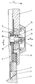
- 1 is the shaft of a shell ski boot designated, the shell is indicated with 2.
- the Shell 2 has an inclined surface 3, which with a Support block 4 of a support part 5 cooperates.
- the sloping surface 3 is at an angle ⁇ to the sole (not shown) of approximately 20 °, in any case> 15 °, inclined.
- the support part 5 is in the vertical direction in the sense of the double arrow 6 guided in a bearing component 7, the bearing component 7 is rigidly connected to the shaft 1.
- a compression spring 8 which between the support block 4 and the Bearing component 7 is arranged.
- the displacement of the support part 5 is by an angled upper end 9 of the support member 5th limited, the representation in the drawing figure the locked position taking the desired template schematically reproduces.
- the locking takes place using a as a pin or bolt trained locking member 10, which against the force of a spring 11 in the direction of the double arrow 12 is slidably mounted in the bearing component 7.
- the direction of displacement the locking member 10 is essentially perpendicular to the direction of displacement of the support member 5, and it is an elongated hole guide 13 is provided.
- An actuator 14 can be designed as a rotary knob, slide or lever and over an oblique groove guide with a dome pin 15 of the locking member 10 cooperate. By twisting or moving of the actuator 14, depending on its specific training, lets are the axial displacement of the locking member 10 effect in the sense of the double arrow 12.
Landscapes
- Health & Medical Sciences (AREA)
- General Health & Medical Sciences (AREA)
- Physical Education & Sports Medicine (AREA)
- Footwear And Its Accessory, Manufacturing Method And Apparatuses (AREA)
- Jib Cranes (AREA)
- Replacement Of Web Rolls (AREA)
- Forklifts And Lifting Vehicles (AREA)
Description
Claims (7)
- Einrichtung zur Freigabe bzw. Verriegelung der Schwenkbarkeit eines Schaftes (1) relativ zur Schale (2) eines Schalenschuhes, wobei ein Lagerbauteil (7) mit dem Schaft (1) verbunden ist, an dem ein Verriegelungsglied (10) verschieblich gelagert ist, dadurch gekennzeichnet, daß im Lagerbauteil (7) ein Stützteil (5) in Höhenrichtung begrenzt verschieblich gelagert ist, und daß das am Lagerbauteil (7) quer zum Stützteil (5) verschieblich gelagerte Verriegelungsglied (10) mit dem Stützteil (5) für die Freigabe oder Verriegelung der begrenzten Verschiebebewegung des Stützteiles (5) zusammenarbeitet.
- Einrichtung nach Anspruch 1, dadurch gekennzeichnet, daß das Stützteil (5) ein steifes Stangen- oder Flachbandprofil aufweist, dessen den Lagerbauteil (7) durchsetzendes oberes Ende (9) verdickt oder abgewinkelt ist und so den lichten Querschnitt der Führung im Lagerbauteil (7) übersteigt, und dessen das Lagerbauteil (7) in Richtung zur Schale (2) überragendes Ende einen Abstützblock (4) trägt.
- Einrichtung nach Anspruch 2, dadurch gekennzeichnet, daß zwischen dem Abstützblock (4) und dem Lagerbauteil (7) wenigstens eine Druckfeder (8) angeordnet ist.
- Einrichtung nach einem der Ansprüche 1 bis 3, dadurch gekennzeichnet, daß das Verriegelungsglied (10) als Zapfen ausgebildet ist, der zwischen zwei Drehendlagen eines Betätigungsgliedes (14) in axialer Richtung verschieblich geführt ist und in einer Endlage mit einer Ausnehmung oder Durchbrechung (16) des Stützteiles (5) formschlüssig zusammenwirkt.
- Einrichtung nach Anspruch 4 mit Anspruch 2, dadurch gekennzeichnet, daß das obere Ende (9) des Stützteiles (5) in einem Abstand von der Ausnehmung oder Durchbrechung (16) angeordnet ist, welcher dem Abstand des Zapfens von einer mit dem Ende (9) zusammenwirkenden Kante des Lagerbauteiles (7) entspricht.
- Einrichtung nach Anspruch 4 oder 5, dadurch gekennzeichnet, daß der Zapfen entgegen der Kraft einer Feder (11) axial verschieblich ist und in seinen beiden Drehendlagen mit Rastausnehmungen einer Schrägnut des Betätigungsgliedes (14) verrastet.
- Einrichtung nach einem der Ansprüche 2 bis 6, dadurch gekennzeichnet, daß die Oberkante der Schale (2), welche mit dem Abstützblock (4) zusammenwirkt, eine zur Schuhspitze geneigte Abstützfläche (3) aufweist, welche mit der Sohlenebene einen Winkel (α) von >15° einschließt, und daß der Abstützblock (4) eine diesem Winkel (α) entsprechend verlaufende Schrägfläche aufweist.
Applications Claiming Priority (3)
| Application Number | Priority Date | Filing Date | Title |
|---|---|---|---|
| AT0190994A AT401849B (de) | 1994-10-10 | 1994-10-10 | Einrichtung zur freigabe bzw. verriegelung der schwenkbarkeit eines schaftes |
| AT1909/94 | 1994-10-10 | ||
| PCT/AT1995/000195 WO1996010931A1 (de) | 1994-10-10 | 1995-10-10 | Einrichtung zur wahlweisen freigabe oder verriegelung eines schwenkbaren schaftes eines schalenschuhes |
Publications (2)
| Publication Number | Publication Date |
|---|---|
| EP0785734A1 EP0785734A1 (de) | 1997-07-30 |
| EP0785734B1 true EP0785734B1 (de) | 1998-07-29 |
Family
ID=3523652
Family Applications (1)
| Application Number | Title | Priority Date | Filing Date |
|---|---|---|---|
| EP95933224A Expired - Lifetime EP0785734B1 (de) | 1994-10-10 | 1995-10-10 | Einrichtung zur wahlweisen freigabe oder verriegelung eines schwenkbaren schaftes eines schalenschuhes |
Country Status (5)
| Country | Link |
|---|---|
| EP (1) | EP0785734B1 (de) |
| JP (1) | JP3509872B2 (de) |
| AT (2) | AT401849B (de) |
| DE (1) | DE59503011D1 (de) |
| WO (1) | WO1996010931A1 (de) |
Family Cites Families (5)
| Publication number | Priority date | Publication date | Assignee | Title |
|---|---|---|---|---|
| DE3504961A1 (de) * | 1984-11-23 | 1986-05-28 | Weinmann Gmbh & Co Kg Fahrrad- Und Motorrad-Teilefabrik, 7700 Singen | Skischuh |
| CH677585A5 (de) * | 1988-09-09 | 1991-06-14 | Lange Int Sa | |
| EP0392981A1 (de) * | 1989-04-14 | 1990-10-17 | Lange International S.A. | Spannvorrichtung für ein Zugseil in einem Skischuh |
| AT398155B (de) * | 1991-07-26 | 1994-10-25 | Tyrolia Freizeitgeraete | Skischuh |
| AT398688B (de) * | 1991-12-02 | 1995-01-25 | Dynafit Skischuh Gmbh | Einstellsystem für skischuhe |
-
1994
- 1994-10-10 AT AT0190994A patent/AT401849B/de not_active IP Right Cessation
-
1995
- 1995-10-10 DE DE59503011T patent/DE59503011D1/de not_active Expired - Fee Related
- 1995-10-10 EP EP95933224A patent/EP0785734B1/de not_active Expired - Lifetime
- 1995-10-10 WO PCT/AT1995/000195 patent/WO1996010931A1/de not_active Ceased
- 1995-10-10 JP JP51220396A patent/JP3509872B2/ja not_active Expired - Fee Related
- 1995-10-10 AT AT95933224T patent/ATE168862T1/de not_active IP Right Cessation
Also Published As
| Publication number | Publication date |
|---|---|
| DE59503011D1 (de) | 1998-09-03 |
| JP3509872B2 (ja) | 2004-03-22 |
| ATE168862T1 (de) | 1998-08-15 |
| WO1996010931A1 (de) | 1996-04-18 |
| EP0785734A1 (de) | 1997-07-30 |
| AT401849B (de) | 1996-12-27 |
| JPH10506814A (ja) | 1998-07-07 |
| ATA190994A (de) | 1996-05-15 |
Similar Documents
| Publication | Publication Date | Title |
|---|---|---|
| DE69612838T2 (de) | Anpassbares prothesengelenk | |
| AT359898B (de) | Sicherheitsskibindung | |
| EP0336113B1 (de) | Fugenüberbrückungsvorrichtung | |
| DE2533337C3 (de) | Auslöseskibindung | |
| AT406932B (de) | Skischuh | |
| DE2414439A1 (de) | Verschlussystem fuer schuhe, insbesondere skischuhe | |
| AT401710B (de) | Skischuh | |
| DE2942806A1 (de) | Vorrichtung zum festhalten eines skistiefelendes auf einem ski, insbesondere bindung fuer einen langlaufski | |
| DE3400089A1 (de) | Alpiner skischuh mit automatischem verschluss | |
| DE3218256A1 (de) | Skistiefel | |
| WO1987006486A1 (fr) | Fixation de ski de fond | |
| DE2513188A1 (de) | Vorrichtung zum montieren einer bremse an einem ski | |
| DE4428154A1 (de) | Anordnung einer Langlaufskibindung und eines daran angepaßten Langlaufskischuhs | |
| EP1297869B1 (de) | Schneegleitbrett, insbesondere Ski | |
| DE69324016T2 (de) | Ganzknieprothese | |
| DE60218415T2 (de) | Langlaufskibindung | |
| WO1992003071A1 (de) | Schnalle für schuhe, insbesondere skischuhe | |
| DE69604323T2 (de) | Schuh mit Vorlageeinstellung des Schaftes | |
| DE1810671A1 (de) | Stelleinrichtung an Fenstern,Tueren od.dgl. | |
| AT401849B (de) | Einrichtung zur freigabe bzw. verriegelung der schwenkbarkeit eines schaftes | |
| AT395512B (de) | Schischuh mit einer schale und einem relativ zur schale schwenkbaren schaft | |
| DE69710013T2 (de) | Schischuh mit einem Schaft aus zwei erweitbaren Teilen | |
| DE10152438B4 (de) | Schneegleitbrett, insbesondere Ski sowie Spreizvorrichtung für ein Schneegleitbrett | |
| DE69515376T2 (de) | Vorrichtung zum Einstellen der Position des Schaftes gegenüber der Schale eines Sportschuhs | |
| DE2835733A1 (de) | Anzeigevorrichtung fuer die ausloesehaerte einer schraubenfeder bei einer sicherheitsskibindung |
Legal Events
| Date | Code | Title | Description |
|---|---|---|---|
| PUAI | Public reference made under article 153(3) epc to a published international application that has entered the european phase |
Free format text: ORIGINAL CODE: 0009012 |
|
| 17P | Request for examination filed |
Effective date: 19970404 |
|
| AK | Designated contracting states |
Kind code of ref document: A1 Designated state(s): AT CH DE FR IT LI |
|
| GRAG | Despatch of communication of intention to grant |
Free format text: ORIGINAL CODE: EPIDOS AGRA |
|
| 17Q | First examination report despatched |
Effective date: 19970918 |
|
| GRAG | Despatch of communication of intention to grant |
Free format text: ORIGINAL CODE: EPIDOS AGRA |
|
| GRAH | Despatch of communication of intention to grant a patent |
Free format text: ORIGINAL CODE: EPIDOS IGRA |
|
| GRAH | Despatch of communication of intention to grant a patent |
Free format text: ORIGINAL CODE: EPIDOS IGRA |
|
| GRAA | (expected) grant |
Free format text: ORIGINAL CODE: 0009210 |
|
| AK | Designated contracting states |
Kind code of ref document: B1 Designated state(s): AT CH DE FR IT LI |
|
| PG25 | Lapsed in a contracting state [announced via postgrant information from national office to epo] |
Ref country code: IT Free format text: LAPSE BECAUSE OF FAILURE TO SUBMIT A TRANSLATION OF THE DESCRIPTION OR TO PAY THE FEE WITHIN THE PRESCRIBED TIME-LIMIT;WARNING: LAPSES OF ITALIAN PATENTS WITH EFFECTIVE DATE BEFORE 2007 MAY HAVE OCCURRED AT ANY TIME BEFORE 2007. THE CORRECT EFFECTIVE DATE MAY BE DIFFERENT FROM THE ONE RECORDED. Effective date: 19980729 Ref country code: FR Free format text: LAPSE BECAUSE OF FAILURE TO SUBMIT A TRANSLATION OF THE DESCRIPTION OR TO PAY THE FEE WITHIN THE PRESCRIBED TIME-LIMIT Effective date: 19980729 |
|
| REF | Corresponds to: |
Ref document number: 168862 Country of ref document: AT Date of ref document: 19980815 Kind code of ref document: T |
|
| REG | Reference to a national code |
Ref country code: CH Ref legal event code: EP |
|
| REF | Corresponds to: |
Ref document number: 59503011 Country of ref document: DE Date of ref document: 19980903 |
|
| PG25 | Lapsed in a contracting state [announced via postgrant information from national office to epo] |
Ref country code: AT Free format text: LAPSE BECAUSE OF NON-PAYMENT OF DUE FEES Effective date: 19981010 |
|
| REG | Reference to a national code |
Ref country code: CH Ref legal event code: NV Representative=s name: E. BLUM & CO. PATENTANWAELTE |
|
| EN | Fr: translation not filed | ||
| PLBE | No opposition filed within time limit |
Free format text: ORIGINAL CODE: 0009261 |
|
| STAA | Information on the status of an ep patent application or granted ep patent |
Free format text: STATUS: NO OPPOSITION FILED WITHIN TIME LIMIT |
|
| 26N | No opposition filed | ||
| PGFP | Annual fee paid to national office [announced via postgrant information from national office to epo] |
Ref country code: CH Payment date: 20031016 Year of fee payment: 9 |
|
| PG25 | Lapsed in a contracting state [announced via postgrant information from national office to epo] |
Ref country code: LI Free format text: LAPSE BECAUSE OF NON-PAYMENT OF DUE FEES Effective date: 20041031 Ref country code: CH Free format text: LAPSE BECAUSE OF NON-PAYMENT OF DUE FEES Effective date: 20041031 |
|
| REG | Reference to a national code |
Ref country code: CH Ref legal event code: PL |
|
| PGFP | Annual fee paid to national office [announced via postgrant information from national office to epo] |
Ref country code: DE Payment date: 20081022 Year of fee payment: 14 |
|
| PG25 | Lapsed in a contracting state [announced via postgrant information from national office to epo] |
Ref country code: DE Free format text: LAPSE BECAUSE OF NON-PAYMENT OF DUE FEES Effective date: 20100501 |