EP0785381B1 - Verfahren zur Regelung stufenloser Getriebe von Kraftfahrzeugen - Google Patents
Verfahren zur Regelung stufenloser Getriebe von Kraftfahrzeugen Download PDFInfo
- Publication number
- EP0785381B1 EP0785381B1 EP97100312A EP97100312A EP0785381B1 EP 0785381 B1 EP0785381 B1 EP 0785381B1 EP 97100312 A EP97100312 A EP 97100312A EP 97100312 A EP97100312 A EP 97100312A EP 0785381 B1 EP0785381 B1 EP 0785381B1
- Authority
- EP
- European Patent Office
- Prior art keywords
- regulating
- ranges
- control
- transmission
- control loop
- Prior art date
- Legal status (The legal status is an assumption and is not a legal conclusion. Google has not performed a legal analysis and makes no representation as to the accuracy of the status listed.)
- Expired - Lifetime
Links
Images
Classifications
-
- F—MECHANICAL ENGINEERING; LIGHTING; HEATING; WEAPONS; BLASTING
- F16—ENGINEERING ELEMENTS AND UNITS; GENERAL MEASURES FOR PRODUCING AND MAINTAINING EFFECTIVE FUNCTIONING OF MACHINES OR INSTALLATIONS; THERMAL INSULATION IN GENERAL
- F16H—GEARING
- F16H61/00—Control functions within control units of change-speed- or reversing-gearings for conveying rotary motion ; Control of exclusively fluid gearing, friction gearing, gearings with endless flexible members or other particular types of gearing
- F16H61/66—Control functions within control units of change-speed- or reversing-gearings for conveying rotary motion ; Control of exclusively fluid gearing, friction gearing, gearings with endless flexible members or other particular types of gearing specially adapted for continuously variable gearings
- F16H61/662—Control functions within control units of change-speed- or reversing-gearings for conveying rotary motion ; Control of exclusively fluid gearing, friction gearing, gearings with endless flexible members or other particular types of gearing specially adapted for continuously variable gearings with endless flexible members
- F16H61/66254—Control functions within control units of change-speed- or reversing-gearings for conveying rotary motion ; Control of exclusively fluid gearing, friction gearing, gearings with endless flexible members or other particular types of gearing specially adapted for continuously variable gearings with endless flexible members controlling of shifting being influenced by a signal derived from the engine and the main coupling
Definitions
- the invention relates to a method according to the preamble of claim 1 as is known from US 4,852,429.
- the drive unit of motor vehicles (the engine and the associated transmission) is increasingly subjected to regulation and control mechanisms in order to optimize the interaction of the engine with the transmission; For example, in order to reduce the fuel consumption of motor vehicles, in addition to improved control of the engine, the gear ratio must also be adapted.
- Automatic transmissions are suitable for this, whereby continuously variable transmissions (CVT transmissions: "Continuous Variable Transmission”) are increasingly used, in which the transmission is adjusted until the desired transmission ratio has been set.
- CVT transmissions Continuous Variable Transmission
- the required gear ratio can be changed continuously (steplessly): by applying the same value of the contact pressure on the two pulley sets - this corresponds to the so-called preload force set the force level for the transmission element;
- preload force set the force level for the transmission element;
- an additional force component for transporting the transmission element is generated, the transmission ratio being able to be varied continuously in arbitrary steps by varying the contact pressure and thus the transport force.
- Adaptive strategies for adapting specified control maps to the driver type (“long-term strategy”: engine power requirement of the respective driver), to the environment (“medium-term strategy”: for example slip detection, trailer travel, ascent) and to the current driving situation (“short-term strategy”) can also be included in the control procedures. : for example overtaking processes) are incorporated.
- long-term strategy engine power requirement of the respective driver
- medium-term strategy for example slip detection, trailer travel, ascent
- short-term strategy can also be included in the control procedures. : for example overtaking processes) are incorporated.
- a method for controlling continuously variable transmissions is known, in which a second control circuit with the time derivative of the transmission input speed as a control variable is subordinate to a first control circuit with the measured transmission input speed.
- the transmission input speed or drive speed is regulated.
- the control circuit has a summation element at the controller input, to which the setpoint of the gearbox input speed as a command variable is supplied as the first summand and the actual value of the gearbox input speed as a control variable as the second summand;
- the control deviation obtained by forming the difference between the two setpoints of the gearbox input speed and the actual value of the gearbox input speed at the output of the summation element is fed to a control element consisting of a proportional controller, limiter and low-pass filter, at whose output (the controller output) the time derivative of the gearbox input speed is pending.
- a second control circuit in the form of an acceleration controller is subordinate to the speed controller, in which the time derivative of the transmission input speed provided by the controller output of the speed controller forms the reference variable; ie in addition to speed control, speed change control takes place.
- the disadvantage of this method of controlling continuously variable transmissions is that it is not possible - often desirable - to control, limit or suppress the control behavior with regard to the transmission transmission ratio control variable, since only the transmission input speed control variable is monitored as a measure of the transmission transmission ratio: e.g.
- the subordinate speed change control can lead to an undesirable change in the gear ratio and thus to an adjustment of the transmission - in particular, this can lead to an undesired running into the so-called mechanical end position of the transmission, in which the strength and / or the life of the transmission element is impaired or the transmission element can be destroyed.
- the invention is based on the object of a method for continuously variable regulation Specify gearboxes of motor vehicles, in which a Monitoring or control of the scheme is made possible.
- a modified two-stage controller with a first control loop as Speed controller and a second control loop subordinate to the first control loop as Speed change controller the influence of the control on the manipulated variable gear ratio as one of the two in the control variable gearbox input speed (speed controller) or in the control variable, time derivative of the transmission input speed (Speed change controller) controls incoming product factors; in particular the influence of the regulation on the Control gear ratio largely in certain control ranges or completely suppressed ("hidden"), so that a (in-sequence the control necessarily, but undesirable) change in the gear ratio is prevented.
- This correction value depends on the function value of a correction function determined by means of a correction element (e.g. by multiplying the function value the correction function with a certain factor), the course of the correction function can be determined or varied depending on various criteria (e.g. depending on the driving situation, the vehicle speed, the gear ratio, the driver type, the size of the control deviation, etc.).
- the Number of times by applying the correction value to the summation element formed control areas can be varied by varying the course of the correction function or their functional values or by varying the correction element the respective requirements are adapted - preferably by appropriate Choice of the course of the correction function defines five control ranges, one controlled Control range in the range of the minimum value of the control variable gear ratio, a controlled control range in the range of the maximum value of the manipulated variable Gear ratio, a normal control range in the range of normal the control variable gear ratio and a transition control range between the two controlled control areas and the "normal" Control range.
- the transition control areas and thus the transitions from a "normal" Control range for a "controlled” control range can be specified arbitrarily - e.g. can either be a stepped (abrupt) transition or a stepless (softer) Transition between a normal "control area” and a "controlled” control area will be realized.
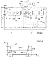
- FIG Block diagram of the controller is shown with the two control loops and the figure 2 shows an example of the course of the correction function.
- the two-stage regulator of the first control circuit 1 for controlling the transmission input speed n IN as product n OUT ⁇ ÜV the transmission output speed N OUT (this is proportional to the speed of the motor vehicle), and the gear ratio UV and from the first Control circuit 1 subordinate to second control circuit 2 (speed change controller) for controlling the time derivative d / dt of the transmission input speed n IN and from the correction element 3 for generating the correction value KW in accordance with the correction function KF.
- the first control circuit 1 has a summation element 11 at the input RE1, to which the setpoint n IN, TARGET of the transmission input speed n IN as the reference variable FG1 and the actual value n IN, ACTUAL the transmission input speed n IN as the control variable RG1 are supplied as the first summand.
- the control deviation ⁇ 1 ( ⁇ 1 n IN, TARGET -n IN, ACTUAL) formed by forming the difference between the two variables n IN, TARGET and n IN, IST at the output of the summation element 11 becomes the control loop element 12 from the proportional transmission element 121, limiter 122 and low-pass filter 1.
- the second control circuit 2 has, at the controller input RE2, a summation element 21 connected to the output RA1 of the control circuit element 12, to which the setpoint d / dt (n IN, TARGET ) of the time derivative d / dt (n IN ) of the transmission input speed n IN is the first summand
- the actual value d / dt (n IN, IST ) of the time derivative d / dt (n IN ) of the transmission input speed n IN is supplied as control variable RG2 as the reference variable FG2 and as the second summand.
- control deviation ⁇ 2 ( ⁇ 2 d / dt (n IN, SHOULD )) - d / dt () formed by forming the difference between the two quantities d / dt (n IN, SHOULD ) and d / dt (n IN, IST ) at the output of the summation element 21. n IN, IST )) is fed to the control element 22, which is designed as a PI controller and which specifies the gear ratio UV via the control element 23 or the controlled system as the manipulated variable SG.
- the multiplication element 24 connected to the output of the actuator 23 is supplied with the manipulated variable SG gear ratio UV as the first product factor and the transmission output speed n OUT as the disturbance variable StG as the second product factor;
- the actual value n IN, ACTUAL gear input speed n IN is formed by multiplying the two variables gear ratio UV and transmission output speed n OUT .
- the actual value n IN, IST of the transmission input speed n IN at the output RA2 of the second control circuit 2 is fed as a controlled variable RG1 to the summation element 11 at the input RE1 of the first control circuit 1 and a differentiating element 25 to form the time derivative, which is then used as the controlled variable RG2 to the summing element 21 is supplied to the control input RE2 of the second control circuit 2.
- the correction element 3 Depending on the correction function KF, the correction element 3 generates a correction value KW and applies this correction value KW to the summation element 21 at the controller input RE2 of the second control circuit 2; by a suitable choice of the correction function KF and the correction element 3, the control behavior of the second control circuit 2 (speed change controller) is influenced in such a way that the influence of the transmission ratio UV on the control variable transmission input speed n IN is controlled.
- the correction value KW on the summation element 21 different control ranges with different control behavior are formed, the number and range limits as well as the transitions between the different control ranges can be varied by a suitable choice of the course of the correction function KF.
- the influence of the factor ÜVd / dt (n OUT ) can be controlled via the correction value KW, ie the specification of the transmission ratio UV resulting from the regulation can be influenced (e.g. the value of the gear ratio UV are kept constant, although it should be varied according to the regulation).
- FIG. 2 shows the exemplary course of a correction function KF with the function value FW shown as a function of the gear ratio UV.
- the function value FW of the correction function KF and therefore also the correction value KW supplied to the summation element 23 of the control circuit 2 (speed change controller) is constant and different from zero;
- the proportion d / dt (ÜV) ⁇ n OUT is just compensated by this correction variable; consequently, the gear ratio UV no longer changes and cannot be influenced by the acceleration or deceleration of the motor vehicle.
- second control area RB2 and fourth control area RB4 is the transition behavior between the control areas RB1 and RB3 or RB3 and RB5 set; the transition takes place in accordance with that shown in FIG Correction function KF approximately in steps by the second control range RB2 and the fourth control range RB4 are made relatively narrow, thereby reducing the function value FW of the correction function KF between the limit values G1 and G2 or the limit values G3 and G4 is changed quickly.
- the course of the correction function can be used for other applications or boundary conditions KF and thus the specification of the different control ranges RB1, RB2, RB3, RB4, RB5 (course, extent, transitions) can be adapted or varied accordingly.
Landscapes
- Engineering & Computer Science (AREA)
- General Engineering & Computer Science (AREA)
- Mechanical Engineering (AREA)
- Control Of Transmission Device (AREA)
Description
Die Antriebseinheit von Kraftfahrzeugen (der Motor und das dazugehörige Getriebe) wird in zunehmendem Maße Regelungs- und Steuerungsmechanismen unterworfen, um das Zusammenspiel des Motors mit dem Getriebe zu optimieren; beispielsweise muß zur Senkung des Kraftstoffverbrauchs von Kraftfahrzeugen neben einer verbesserten Ansteuerung des Motors auch die Getriebeübersetzung angepaßt werden. Hierfür bieten sich Automatikgetriebe an, wobei in zunehmendem Maße stufenlose Getriebe (CVT-Getriebe: "Continuous Variable Transmission") eingesetzt werden, bei denen das Getriebe so lange verstellt wird, bis sich das gewünschte Getriebeübersetzungsverhältnis eingestellt hat. Durch ein zwischen den Scheiben zweier Scheibensätze angeordnetes Transmissionselement (Kette, Band, Riemen etc.) kann das erforderliche Getriebeübersetzungsverhältnis kontinuierlich (stufenlos) verändert werden: durch Anlegen des gleichen Werts der Anpreßkraft auf die beiden Scheibensätze - dies entspricht der sog. Vorspannkraft -, wird das Kraftniveau für das Transmissionselement eingestellt; durch Vorgabe unterschiedlicher Werte der Anpreßkraft auf die beiden Scheibensätze wird eine zusätzliche Kraftkomponente zum Transport des Transmissionselements erzeugt, wobei durch Variation der Anpreßkraft und damit der Transportkraft das Getriebeübersetzungsverhältnis in beliebigen Schritten stufenlos variiert werden kann. In die Regelverfahren können zudem adaptive Strategien zur Anpassung vorgegebener Regelkennfelder an den Fahrertyp ("Langzeitstrategie": Motorleistungsbedarf des jeweiligen Fahrers), an die Umwelt ("mittelfristige Strategie": beispielsweise Schlupferkennung, Anhängerfahrt, Bergfahrt) und an die aktuelle Fahrsituation ("Kurzzeitstrategie": beispielsweise Überholvorgänge) inkorporiert werden.
Aus der eingangs erwähnten gattungsgemäßen US 4,852,429 ist ein Verfahren zur Regelung stufenlos verstellbarer Getriebe bekannt, bei dem einem ersten Regelkreis mit der gemessenen Getriebeeingangsdrehzahl als Regelgröße ein zweiter Regelkreis mit der zeitlichen Ableitung der Getriebeeingangsdrehzahl als Regelgröße unterlagert ist. Bei dem als Drehzahlregler ausgebildeten Regelkreis wird die Getriebeeingangsdrehzahl bzw. Antriebsdrehzahl geregelt. Hierzu weist der Regelkreis am Reglereingang ein Summationsglied auf, dem als erster Summand der Sollwert der Getriebeeingangsdrehzahl als Führungsgröße und als zweiter Summand der Istwert der Getriebeeingangsdrehzahl als Regelgröße zugeführt wird; die durch Differenzbildung der beiden Größen Sollwert der Getriebeeingangsdrehzahl und Istwert der Getriebeeingangsdrehzahl am Ausgang des Summationsglieds erhaltene Regelabweichung wird einem Regelglied aus Proportionalregler, Begrenzer und Tiefpaß zugeführt, an dessen Ausgang (dem Reglerausgang) die zeitliche Ableitung der Getriebeeingangsdrehzahl ansteht. zur Verbesserung des Regelverhaltens ist dem Drehzahlregler ein zweiter Regelkreis in der Art eines Beschleunigungsreglers unterlagert, bei dem die vom Reglerausgang des Drehzahlreglers als Sollwert bereitgestellte zeitliche Ableitung der Getriebeeingangsdrehzahl die Führungsgröße bildet; d.h. zusätzlich zur Drehzahlregelung erfolgt eine Drehzahländerungsregelung.
Nachteilig bei diesem Verfahren zur Regelung stufenlos verstellbarer Getriebe ist, daß eine - oftmals wünschenswerte - Kontrolle, Begrenzung oder Unterdrückung des Regelverhaltens bezüglich der Stellgröße Getriebeübersetzungsverhältnis nicht möglich ist, da nur die Regelgröße Getriebeeingangsdrehzahl als Maß für das Getriebeübersetzungsverhältnis überwacht wird: bsp. kann es daher beim Beschleunigen oder Verzögern des Fahrzeugs durch die unterlagerte Drehzahländerungsregelung zu einer unerwünschten Änderung des Getriebeübersetzungsverhältnisses und damit zu einer Verstellung des Getriebes kommen - insbesondere kann hierdurch ein ungewolltes Hineinlaufen in die sog. mechanische Endlage des Getriebes auftreten, in der die Festigkeit und/oder die Lebensdauer des Transmissionselements beeinträchtigt bzw. das Transmissionselement zerstört werden kann.
Der zweite Regelkreis 2 weist am Reglereingang RE2 ein mit dem Ausgang RA1 des Regelkreisglieds 12 verbundenes Summationsglied 21 auf, dem als erster Summand der Sollwert d/dt(nIN,SOLL) der zeitlichen Ableitung d/dt(nIN) der Getriebeeingangsdrehzahl nIN als Führungsgröße FG2 und als zweiter Summand der Istwert d/dt(nIN,IST) der zeitlichen Ableitung d/dt(nIN) der Getriebeeingangsdrehzahl nIN als Regelgröße RG2 zugeführt wird. Die durch Differenzbildung der beiden Größen d/dt(nIN,SOLL) und d/dt(nIN,IST) am Ausgang des Summationsglieds 21 gebildete Regelabweichung Δ2 (Δ2 = d/dt(nIN,SOLL) - d/dt(nIN,IST)) wird dem als Pl-Regler ausgebildeten Regelglied 22 zugeführt, das über das Stellglied 23 bzw. die Regelstrecke als Stellgröße SG das Getriebeübersetzungsverhältnis ÜV vorgibt. Dem am Ausgang des Stellglieds 23 angeschlossenen Multiplikationsglied 24 wird als erster Produktfaktor die Stellgröße SG Getriebeübersetzungsverhältnis ÜV und als zweiter Produktfaktor die als Störgröße StG fungierende Cetriebeausgangsdrehzahl nOUT zugeführt; durch Multiplikation der beiden Größen Getriebeübersetzungsverhältnis ÜV und Getriebeausgangsdrehzahl nOUT wird der Istwert nIN,IST der Getriebeeingangsdrehzahl nIN gebildet. Der Istwert nIN,IST der Getriebeeingangsdrehzahl nIN am Ausgang RA2 des zweiten Regelkreises 2 wird als Regelgröße RG1 dem Summationsglied 11 am Eingang RE1 des ersten Regelkreises 1 und einem Differenzierglied 25 zur Bildung der zeitlichen Ableitung zugeführt, die dann als Regelgröße RG2 dem Summationsglied 21 am Reglereingang RE2 des zweiten Regelkreises 2 zugeführt wird.
Claims (8)
- Verfahren zur Regelung stufenlos verstellbarer Getriebe von Kraftfahrzeugen bei demdadurch gekennzeichnet,mit einem ersten Regelkreis (1) als Drehzahlregler die Getriebeeingangsdrehzahl (nIN) geregelt wird, wobei einem Summationsglied (11) am Eingang (RE1) eines Regelkreisglieds (12) die Regelabweichung der Getriebeeingangsdrehzahl (nIN) zugeführt wird,mit einem dem ersten Regelkreis (1) unterlagerten zweiten Regelkreis (2) als Drehzahländerungsregler die zeitliche Ableitung (d/dt) der Getriebeeingangsdrehzahl (nIN) geregelt wird, wobei ein Summationsglied (21) am Reglereingang (RE2) des unterlagerten zweiten Regelkreises (2) mit dem Ausgang (RA1) des Regelkreisglieds (12) des ersten Regelkreises (1) verbunden wird,daß die aus dem Produkt der Getriebeausgangsdrehzahl (nOUT) und des Getriebeübersetzungsverhältnisses (ÜV) berechnete Getriebeeingangsdrehzahl (nIN) geregelt wird,und daß das Summationsglied (11; 21) eines der beiden Regelkreise (1; 2) mit einem von einem Korrekturglied (3) gebildeten, vom Funktionswert (FW) einer Korrekturfunktion (KF) abhängigen Korrekturwert (KW) beaufschlagt wird, durch den Regelbereiche (RB1, RB2, RB3, RB4, RB5) für ein unterschiedliches Regelverhalten vorgegeben werden.
- Verfahren nach Anspruch 1, dadurch gekennzeichnet, daß Anzahl, Bereichsgrenzen und Regelverhalten für die Regelbereiche (RB1, RB2, RB3, RB4, RB5) nach Maßgabe vom Betrieb des Kraftfahrzeugs abhängiger Parameter oder Randbedingungen durch den Verlauf der Korrekturfunktion (KF) vorgegeben werden.
- Verfahren nach Anspruch 2, dadurch gekennzeichnet, daß Anzahl, Bereichsgrenzen und Regelverhalten für die Regelbereiche (RB1, RB2, RB3, RB4, RB5) nach Maßgabe der Fahrsituation und/oder der Geschwindigkeit des Kraftfahrzeugs und/oder des Getriebeübersetzungsverhältnisses (ÜV) und/oder des Fahrertyps und/oder der Größe der Regelabweichung vorgegeben werden.
- Verfahren nach einem der Ansprüche 1 bis 3, dadurch gekennzeichnet, daß mit dem Korrekturwert (KW) als Regelbereiche vorgegeben werden:mindestens ein normaler Regelbereich (RB3), in dem keine Beeinflussung des Regelverhaltens erfolgt,mindestens ein kontrollierter Regelbereich (RB1, RB5), in dem eine Beeinflussung des Regelverhaltens erfolgt,jeweils ein Übergangsbereich (RB2, RB4) zwischen einem kontrollierten Regelbereich (RB1, RB5) und einem normalen Regelbereich (RB3).
- Verfahren nach Anspruch 4, dadurch gekennzeichnet, daß in den kontrollierten Regelbereichen (RB1, RB5) die Auswirkung der Regelung auf die Stellgröße Getriebeübersetzungsverhältnis (ÜV) zumindest weitgehend unterdrückt wird.
- Verfahren nach Anspruch 5, dadurch gekennzeichnet, daß in den kontrollierten Regelbereichen (RB1, RB5) die Auswirkung der Regelung auf die Stellgröße Getriebeübersetzungsverhältnis (ÜV) vollständig unterdrückt wird.
- Verfahren nach einem der Ansprüche 4 bis 6, dadurch gekennzeichnet, daß die Übergangsbereiche (RB2, RB4) so gewählt werden, daß der Übergang zwischen den kontrollierten Regelbereichen (RB1, RB5) und den normalen Regelbereichen (RB3) sprunghaft erfolgt.
- Verfahren nach einem der Ansprüche 4 bis 6, dadurch gekennzeichnet, daß die Übergangsbereiche (RB2, RB4) so gewählt werden, daß der Übergang zwischen den kontrollierten Regelbereichen (RB1, RB5) und den normalen Regelbereichen (RB3) stetig und/oder kontinuierlich erfolgt.
Applications Claiming Priority (2)
| Application Number | Priority Date | Filing Date | Title |
|---|---|---|---|
| DE19602032A DE19602032C2 (de) | 1996-01-20 | 1996-01-20 | Verfahren zur Regelung stufenloser Getriebe von Kraftfahrzeugen |
| DE19602032 | 1996-01-20 |
Publications (2)
| Publication Number | Publication Date |
|---|---|
| EP0785381A1 EP0785381A1 (de) | 1997-07-23 |
| EP0785381B1 true EP0785381B1 (de) | 2001-10-24 |
Family
ID=7783279
Family Applications (1)
| Application Number | Title | Priority Date | Filing Date |
|---|---|---|---|
| EP97100312A Expired - Lifetime EP0785381B1 (de) | 1996-01-20 | 1997-01-10 | Verfahren zur Regelung stufenloser Getriebe von Kraftfahrzeugen |
Country Status (3)
| Country | Link |
|---|---|
| US (1) | US5983152A (de) |
| EP (1) | EP0785381B1 (de) |
| DE (1) | DE19602032C2 (de) |
Families Citing this family (7)
| Publication number | Priority date | Publication date | Assignee | Title |
|---|---|---|---|---|
| DE19742604B4 (de) * | 1997-09-26 | 2012-01-26 | Volkswagen Ag | Verfahren zur Übersetzungsregelung eines stufenlosen Automatikgetriebes (CVT-Getriebe) eines Kraftfahrzeugs |
| US6157884A (en) * | 1998-09-25 | 2000-12-05 | Nissan Motor Co., Ltd. | Speed ratio control device and control method for automatic transmission |
| DE19851113A1 (de) * | 1998-11-06 | 2000-05-11 | Zahnradfabrik Friedrichshafen | Verfahren zur Übersetzungsregelung eines CVT-Getriebes mit elektrohydraulischer Ansteuerung |
| IL141094A0 (en) | 2001-01-25 | 2002-02-10 | Ran Siman Tov | Continuous variable transmission |
| DE10111607A1 (de) * | 2001-03-10 | 2002-10-31 | Conti Temic Microelectronic | Verfahren zur Steuerung eines stufenlosen Getriebes |
| US7110869B2 (en) * | 2003-10-14 | 2006-09-19 | General Motors Corporation | Hybrid transmission member speed determination, sensor diagnostics and fault recovery |
| DE102004038370B4 (de) * | 2004-08-06 | 2009-06-25 | Austriamicrosystems Ag | Adaptive Regelvorrichtung, Verwendung der Regelvorrichtung, Sensor mit einer derartigen Regelvorrichtung und adaptives Verfahren zur Selbstkompensation von Störsignalen eines Sensors |
Family Cites Families (15)
| Publication number | Priority date | Publication date | Assignee | Title |
|---|---|---|---|---|
| DE3636463A1 (de) * | 1986-10-25 | 1988-05-05 | Daimler Benz Ag | Verfahren und vorrichtung zur steuerung des stufenlos veraenderlichen uebersetzungsverhaeltnisses eines kegelscheibenumschlingungsgetriebes in einem kraftfahrzeug |
| US4867732A (en) * | 1987-08-21 | 1989-09-19 | Toyota Jidosha Kabushiki Kaisha | Control device for belt-and-pulley type continuously variable transmission for a vehicle |
| GB2220038A (en) * | 1988-06-28 | 1989-12-28 | Christopher David Whelan | A constant speed drive for electrical generators |
| JP2741041B2 (ja) * | 1988-10-14 | 1998-04-15 | 富士重工業株式会社 | 無段変速機の変速制御装置 |
| EP0412758B1 (de) * | 1989-08-09 | 1994-11-02 | Toyota Jidosha Kabushiki Kaisha | Hydraulisches Steuerungssystem eines stufenlosen Keilriemengetriebes mit einer ausfallsicheren Schutzanordnung |
| JPH03189456A (ja) * | 1989-12-18 | 1991-08-19 | Mazda Motor Corp | 無段変速機の変速制御装置 |
| NL9000860A (nl) * | 1990-04-12 | 1991-11-01 | Doornes Transmissie Bv | Elektronisch geregelde continu variabele transmissie. |
| JPH05126239A (ja) * | 1991-06-29 | 1993-05-21 | Mazda Motor Corp | 車両用無段変速機の変速制御装置 |
| NL9200638A (nl) * | 1992-04-06 | 1993-11-01 | Doornes Transmissie Bv | Continu variabele transmissie met regelsysteem. |
| NL9201051A (nl) * | 1992-06-15 | 1994-01-03 | Doornes Transmissie Bv | Werkwijze voor het beinvloeden van het rijgedrag van een voertuig met een continu variabele transmissie. |
| FR2699978B1 (fr) * | 1992-12-29 | 1995-03-17 | Peugeot | Dispositif de commande pour boîte de vitesses automatique, notamment de véhicule automobile. |
| JP3367565B2 (ja) * | 1993-04-09 | 2003-01-14 | スズキ株式会社 | 連続可変変速機の変速制御方法 |
| NL9401313A (nl) * | 1994-08-15 | 1996-03-01 | Doornes Transmissie Bv | Continu variabele transmissie. |
| NL9401747A (nl) * | 1994-10-21 | 1996-06-03 | Doornes Transmissie Bv | Werkwijze en inrichting voor het regelen van de overbrengingsverhouding van een continu variabele transmissie. |
| JP3460341B2 (ja) * | 1994-11-28 | 2003-10-27 | 日産自動車株式会社 | 摩擦車式無段変速機の変速制御装置 |
-
1996
- 1996-01-20 DE DE19602032A patent/DE19602032C2/de not_active Expired - Lifetime
-
1997
- 1997-01-08 US US08/780,416 patent/US5983152A/en not_active Expired - Lifetime
- 1997-01-10 EP EP97100312A patent/EP0785381B1/de not_active Expired - Lifetime
Also Published As
| Publication number | Publication date |
|---|---|
| US5983152A (en) | 1999-11-09 |
| DE19602032A1 (de) | 1997-07-24 |
| DE19602032C2 (de) | 2000-06-15 |
| EP0785381A1 (de) | 1997-07-23 |
Similar Documents
| Publication | Publication Date | Title |
|---|---|---|
| DE3930911C2 (de) | Fahrgeschwindigkeitsregler für ein Kraftfahrzeug | |
| DE102019208698B4 (de) | Zwischenfahrzeugabstand-Steuervorrichtung | |
| DE69925211T2 (de) | Abstandsbezogenes Fahrgeschwindigkeitsregelsystem für Kraftfahrzeuge | |
| DE60120602T2 (de) | Fahrgeschwindigkeitsregelsystem eines fahrzeugs | |
| EP0840863B1 (de) | System zur Regelung des Übersetzungsverhältnisses eines stufenlosen Getriebes | |
| DE19620929A1 (de) | Längsregelsystem für Kraftfahrzeuge mit haptischem Gaspedal | |
| DE19715132B4 (de) | Steuergerät und Verfahren zur Steuerung | |
| DE3636463C2 (de) | ||
| EP1423289A1 (de) | Geschwindigkeitsregelung eines kraftfahrzeuges mit automatisiertem schaltgetriebe | |
| DE69812806T2 (de) | Anpassungsfähige Steuereinrichtung für ein stufenloses Getriebe | |
| EP0785382B1 (de) | Verfahren zur Regelung stufenloser Getriebe von Kraftfahrzeugen | |
| EP1108922B1 (de) | Verfahren und Vorrichtung zur Steuerung eines stufenlosen Automatikgetriebes | |
| DE19602032C2 (de) | Verfahren zur Regelung stufenloser Getriebe von Kraftfahrzeugen | |
| DE4229585A1 (de) | Vorrichtung zur Regelung des Übersetzungsverhältnisses eines stufenlosen Getriebes | |
| DE19858294A1 (de) | Verfahren zur Fahrgeschwindigkeitsregelung eines Kraftfahrzeuges | |
| DE2755202C2 (de) | ||
| EP0657668A1 (de) | Verfahren zur Steuerung der Antriebseinheit von Kraftfahrzeugen | |
| DE69309526T2 (de) | Stufenloses Getriebe mit Steuersystem | |
| DE19943332A1 (de) | Verfahren zur Regelung der Fahrzeugbeschleunigung für ein Kraftfahrzeug mit einem stufenlosen Automatgetriebe | |
| DE19547716B4 (de) | Verfahren und Vorrichtung zum Regeln bzw. Begrenzen der Geschwindigkeit eines Fahrzeugs | |
| DE10353978B4 (de) | Verfahren zur Einstellung einer Übersetzung eines stufenlosen Automatgetriebes | |
| EP1578635B1 (de) | Verfahren und vorrichtung zur steuerung einer kupplung innerhalb eines kraftfahrzeugtriebstrangs | |
| DE19649483B4 (de) | Vorrichtung und Verfahren zur automatischen Übersetzungsverstellung | |
| DE19946905B4 (de) | Antriebsschlupfregelsystem | |
| WO2002073071A2 (de) | Verfahren zur steuerung eines stufenlosen getriebes |
Legal Events
| Date | Code | Title | Description |
|---|---|---|---|
| PUAI | Public reference made under article 153(3) epc to a published international application that has entered the european phase |
Free format text: ORIGINAL CODE: 0009012 |
|
| 17P | Request for examination filed |
Effective date: 19970526 |
|
| AK | Designated contracting states |
Kind code of ref document: A1 Designated state(s): FR GB IT SE |
|
| 17Q | First examination report despatched |
Effective date: 20000124 |
|
| RAP1 | Party data changed (applicant data changed or rights of an application transferred) |
Owner name: TEMIC TELEFUNKEN MICROELECTRONIC GMBH |
|
| GRAG | Despatch of communication of intention to grant |
Free format text: ORIGINAL CODE: EPIDOS AGRA |
|
| GRAG | Despatch of communication of intention to grant |
Free format text: ORIGINAL CODE: EPIDOS AGRA |
|
| GRAG | Despatch of communication of intention to grant |
Free format text: ORIGINAL CODE: EPIDOS AGRA |
|
| GRAH | Despatch of communication of intention to grant a patent |
Free format text: ORIGINAL CODE: EPIDOS IGRA |
|
| GRAH | Despatch of communication of intention to grant a patent |
Free format text: ORIGINAL CODE: EPIDOS IGRA |
|
| ITF | It: translation for a ep patent filed | ||
| RBV | Designated contracting states (corrected) |
Designated state(s): FR GB IT SE |
|
| GRAA | (expected) grant |
Free format text: ORIGINAL CODE: 0009210 |
|
| REG | Reference to a national code |
Ref country code: DE Ref legal event code: 8566 |
|
| RAP1 | Party data changed (applicant data changed or rights of an application transferred) |
Owner name: CONTI TEMIC MICROELECTRONIC GMBH |
|
| AK | Designated contracting states |
Kind code of ref document: B1 Designated state(s): FR GB IT SE |
|
| REG | Reference to a national code |
Ref country code: GB Ref legal event code: IF02 |
|
| GBT | Gb: translation of ep patent filed (gb section 77(6)(a)/1977) |
Effective date: 20020105 |
|
| ET | Fr: translation filed | ||
| PLBE | No opposition filed within time limit |
Free format text: ORIGINAL CODE: 0009261 |
|
| STAA | Information on the status of an ep patent application or granted ep patent |
Free format text: STATUS: NO OPPOSITION FILED WITHIN TIME LIMIT |
|
| 26N | No opposition filed | ||
| PGFP | Annual fee paid to national office [announced via postgrant information from national office to epo] |
Ref country code: GB Payment date: 20090122 Year of fee payment: 13 |
|
| PGFP | Annual fee paid to national office [announced via postgrant information from national office to epo] |
Ref country code: SE Payment date: 20090114 Year of fee payment: 13 Ref country code: IT Payment date: 20090128 Year of fee payment: 13 |
|
| GBPC | Gb: european patent ceased through non-payment of renewal fee |
Effective date: 20100110 |
|
| EUG | Se: european patent has lapsed | ||
| PG25 | Lapsed in a contracting state [announced via postgrant information from national office to epo] |
Ref country code: GB Free format text: LAPSE BECAUSE OF NON-PAYMENT OF DUE FEES Effective date: 20100110 |
|
| PG25 | Lapsed in a contracting state [announced via postgrant information from national office to epo] |
Ref country code: IT Free format text: LAPSE BECAUSE OF NON-PAYMENT OF DUE FEES Effective date: 20100110 |
|
| PG25 | Lapsed in a contracting state [announced via postgrant information from national office to epo] |
Ref country code: SE Free format text: LAPSE BECAUSE OF NON-PAYMENT OF DUE FEES Effective date: 20100111 |
|
| REG | Reference to a national code |
Ref country code: FR Ref legal event code: PLFP Year of fee payment: 19 |
|
| PGFP | Annual fee paid to national office [announced via postgrant information from national office to epo] |
Ref country code: FR Payment date: 20150122 Year of fee payment: 19 |
|
| REG | Reference to a national code |
Ref country code: FR Ref legal event code: ST Effective date: 20160930 |
|
| PG25 | Lapsed in a contracting state [announced via postgrant information from national office to epo] |
Ref country code: FR Free format text: LAPSE BECAUSE OF NON-PAYMENT OF DUE FEES Effective date: 20160201 |