EP1578635B1 - Verfahren und vorrichtung zur steuerung einer kupplung innerhalb eines kraftfahrzeugtriebstrangs - Google Patents
Verfahren und vorrichtung zur steuerung einer kupplung innerhalb eines kraftfahrzeugtriebstrangs Download PDFInfo
- Publication number
- EP1578635B1 EP1578635B1 EP03785792A EP03785792A EP1578635B1 EP 1578635 B1 EP1578635 B1 EP 1578635B1 EP 03785792 A EP03785792 A EP 03785792A EP 03785792 A EP03785792 A EP 03785792A EP 1578635 B1 EP1578635 B1 EP 1578635B1
- Authority
- EP
- European Patent Office
- Prior art keywords
- control
- clutch
- controlled variable
- control loop
- drive train
- Prior art date
- Legal status (The legal status is an assumption and is not a legal conclusion. Google has not performed a legal analysis and makes no representation as to the accuracy of the status listed.)
- Expired - Lifetime
Links
Images
Classifications
-
- B—PERFORMING OPERATIONS; TRANSPORTING
- B60—VEHICLES IN GENERAL
- B60W—CONJOINT CONTROL OF VEHICLE SUB-UNITS OF DIFFERENT TYPE OR DIFFERENT FUNCTION; CONTROL SYSTEMS SPECIALLY ADAPTED FOR HYBRID VEHICLES; ROAD VEHICLE DRIVE CONTROL SYSTEMS FOR PURPOSES NOT RELATED TO THE CONTROL OF A PARTICULAR SUB-UNIT
- B60W10/00—Conjoint control of vehicle sub-units of different type or different function
- B60W10/02—Conjoint control of vehicle sub-units of different type or different function including control of driveline clutches
-
- B—PERFORMING OPERATIONS; TRANSPORTING
- B60—VEHICLES IN GENERAL
- B60K—ARRANGEMENT OR MOUNTING OF PROPULSION UNITS OR OF TRANSMISSIONS IN VEHICLES; ARRANGEMENT OR MOUNTING OF PLURAL DIVERSE PRIME-MOVERS IN VEHICLES; AUXILIARY DRIVES FOR VEHICLES; INSTRUMENTATION OR DASHBOARDS FOR VEHICLES; ARRANGEMENTS IN CONNECTION WITH COOLING, AIR INTAKE, GAS EXHAUST OR FUEL SUPPLY OF PROPULSION UNITS IN VEHICLES
- B60K6/00—Arrangement or mounting of plural diverse prime-movers for mutual or common propulsion, e.g. hybrid propulsion systems comprising electric motors and internal combustion engines
- B60K6/20—Arrangement or mounting of plural diverse prime-movers for mutual or common propulsion, e.g. hybrid propulsion systems comprising electric motors and internal combustion engines the prime-movers consisting of electric motors and internal combustion engines, e.g. HEVs
- B60K6/42—Arrangement or mounting of plural diverse prime-movers for mutual or common propulsion, e.g. hybrid propulsion systems comprising electric motors and internal combustion engines the prime-movers consisting of electric motors and internal combustion engines, e.g. HEVs characterised by the architecture of the hybrid electric vehicle
- B60K6/48—Parallel type
-
- B—PERFORMING OPERATIONS; TRANSPORTING
- B60—VEHICLES IN GENERAL
- B60W—CONJOINT CONTROL OF VEHICLE SUB-UNITS OF DIFFERENT TYPE OR DIFFERENT FUNCTION; CONTROL SYSTEMS SPECIALLY ADAPTED FOR HYBRID VEHICLES; ROAD VEHICLE DRIVE CONTROL SYSTEMS FOR PURPOSES NOT RELATED TO THE CONTROL OF A PARTICULAR SUB-UNIT
- B60W10/00—Conjoint control of vehicle sub-units of different type or different function
- B60W10/04—Conjoint control of vehicle sub-units of different type or different function including control of propulsion units
- B60W10/06—Conjoint control of vehicle sub-units of different type or different function including control of propulsion units including control of combustion engines
-
- B—PERFORMING OPERATIONS; TRANSPORTING
- B60—VEHICLES IN GENERAL
- B60W—CONJOINT CONTROL OF VEHICLE SUB-UNITS OF DIFFERENT TYPE OR DIFFERENT FUNCTION; CONTROL SYSTEMS SPECIALLY ADAPTED FOR HYBRID VEHICLES; ROAD VEHICLE DRIVE CONTROL SYSTEMS FOR PURPOSES NOT RELATED TO THE CONTROL OF A PARTICULAR SUB-UNIT
- B60W10/00—Conjoint control of vehicle sub-units of different type or different function
- B60W10/04—Conjoint control of vehicle sub-units of different type or different function including control of propulsion units
- B60W10/08—Conjoint control of vehicle sub-units of different type or different function including control of propulsion units including control of electric propulsion units, e.g. motors or generators
-
- B—PERFORMING OPERATIONS; TRANSPORTING
- B60—VEHICLES IN GENERAL
- B60W—CONJOINT CONTROL OF VEHICLE SUB-UNITS OF DIFFERENT TYPE OR DIFFERENT FUNCTION; CONTROL SYSTEMS SPECIALLY ADAPTED FOR HYBRID VEHICLES; ROAD VEHICLE DRIVE CONTROL SYSTEMS FOR PURPOSES NOT RELATED TO THE CONTROL OF A PARTICULAR SUB-UNIT
- B60W30/00—Purposes of road vehicle drive control systems not related to the control of a particular sub-unit, e.g. of systems using conjoint control of vehicle sub-units
- B60W30/18—Propelling the vehicle
- B60W30/1819—Propulsion control with control means using analogue circuits, relays or mechanical links
-
- B—PERFORMING OPERATIONS; TRANSPORTING
- B60—VEHICLES IN GENERAL
- B60W—CONJOINT CONTROL OF VEHICLE SUB-UNITS OF DIFFERENT TYPE OR DIFFERENT FUNCTION; CONTROL SYSTEMS SPECIALLY ADAPTED FOR HYBRID VEHICLES; ROAD VEHICLE DRIVE CONTROL SYSTEMS FOR PURPOSES NOT RELATED TO THE CONTROL OF A PARTICULAR SUB-UNIT
- B60W30/00—Purposes of road vehicle drive control systems not related to the control of a particular sub-unit, e.g. of systems using conjoint control of vehicle sub-units
- B60W30/18—Propelling the vehicle
- B60W30/20—Reducing vibrations in the driveline
-
- F—MECHANICAL ENGINEERING; LIGHTING; HEATING; WEAPONS; BLASTING
- F16—ENGINEERING ELEMENTS AND UNITS; GENERAL MEASURES FOR PRODUCING AND MAINTAINING EFFECTIVE FUNCTIONING OF MACHINES OR INSTALLATIONS; THERMAL INSULATION IN GENERAL
- F16D—COUPLINGS FOR TRANSMITTING ROTATION; CLUTCHES; BRAKES
- F16D48/00—External control of clutches
- F16D48/06—Control by electric or electronic means, e.g. of fluid pressure
-
- F—MECHANICAL ENGINEERING; LIGHTING; HEATING; WEAPONS; BLASTING
- F16—ENGINEERING ELEMENTS AND UNITS; GENERAL MEASURES FOR PRODUCING AND MAINTAINING EFFECTIVE FUNCTIONING OF MACHINES OR INSTALLATIONS; THERMAL INSULATION IN GENERAL
- F16H—GEARING
- F16H61/00—Control functions within control units of change-speed- or reversing-gearings for conveying rotary motion ; Control of exclusively fluid gearing, friction gearing, gearings with endless flexible members or other particular types of gearing
- F16H61/04—Smoothing ratio shift
- F16H61/0437—Smoothing ratio shift by using electrical signals
-
- B—PERFORMING OPERATIONS; TRANSPORTING
- B60—VEHICLES IN GENERAL
- B60L—PROPULSION OF ELECTRICALLY-PROPELLED VEHICLES; SUPPLYING ELECTRIC POWER FOR AUXILIARY EQUIPMENT OF ELECTRICALLY-PROPELLED VEHICLES; ELECTRODYNAMIC BRAKE SYSTEMS FOR VEHICLES IN GENERAL; MAGNETIC SUSPENSION OR LEVITATION FOR VEHICLES; MONITORING OPERATING VARIABLES OF ELECTRICALLY-PROPELLED VEHICLES; ELECTRIC SAFETY DEVICES FOR ELECTRICALLY-PROPELLED VEHICLES
- B60L2240/00—Control parameters of input or output; Target parameters
- B60L2240/40—Drive Train control parameters
- B60L2240/42—Drive Train control parameters related to electric machines
- B60L2240/421—Speed
-
- B—PERFORMING OPERATIONS; TRANSPORTING
- B60—VEHICLES IN GENERAL
- B60L—PROPULSION OF ELECTRICALLY-PROPELLED VEHICLES; SUPPLYING ELECTRIC POWER FOR AUXILIARY EQUIPMENT OF ELECTRICALLY-PROPELLED VEHICLES; ELECTRODYNAMIC BRAKE SYSTEMS FOR VEHICLES IN GENERAL; MAGNETIC SUSPENSION OR LEVITATION FOR VEHICLES; MONITORING OPERATING VARIABLES OF ELECTRICALLY-PROPELLED VEHICLES; ELECTRIC SAFETY DEVICES FOR ELECTRICALLY-PROPELLED VEHICLES
- B60L2240/00—Control parameters of input or output; Target parameters
- B60L2240/40—Drive Train control parameters
- B60L2240/42—Drive Train control parameters related to electric machines
- B60L2240/423—Torque
-
- B—PERFORMING OPERATIONS; TRANSPORTING
- B60—VEHICLES IN GENERAL
- B60L—PROPULSION OF ELECTRICALLY-PROPELLED VEHICLES; SUPPLYING ELECTRIC POWER FOR AUXILIARY EQUIPMENT OF ELECTRICALLY-PROPELLED VEHICLES; ELECTRODYNAMIC BRAKE SYSTEMS FOR VEHICLES IN GENERAL; MAGNETIC SUSPENSION OR LEVITATION FOR VEHICLES; MONITORING OPERATING VARIABLES OF ELECTRICALLY-PROPELLED VEHICLES; ELECTRIC SAFETY DEVICES FOR ELECTRICALLY-PROPELLED VEHICLES
- B60L2240/00—Control parameters of input or output; Target parameters
- B60L2240/40—Drive Train control parameters
- B60L2240/44—Drive Train control parameters related to combustion engines
- B60L2240/443—Torque
-
- B—PERFORMING OPERATIONS; TRANSPORTING
- B60—VEHICLES IN GENERAL
- B60W—CONJOINT CONTROL OF VEHICLE SUB-UNITS OF DIFFERENT TYPE OR DIFFERENT FUNCTION; CONTROL SYSTEMS SPECIALLY ADAPTED FOR HYBRID VEHICLES; ROAD VEHICLE DRIVE CONTROL SYSTEMS FOR PURPOSES NOT RELATED TO THE CONTROL OF A PARTICULAR SUB-UNIT
- B60W20/00—Control systems specially adapted for hybrid vehicles
-
- B—PERFORMING OPERATIONS; TRANSPORTING
- B60—VEHICLES IN GENERAL
- B60W—CONJOINT CONTROL OF VEHICLE SUB-UNITS OF DIFFERENT TYPE OR DIFFERENT FUNCTION; CONTROL SYSTEMS SPECIALLY ADAPTED FOR HYBRID VEHICLES; ROAD VEHICLE DRIVE CONTROL SYSTEMS FOR PURPOSES NOT RELATED TO THE CONTROL OF A PARTICULAR SUB-UNIT
- B60W50/00—Details of control systems for road vehicle drive control not related to the control of a particular sub-unit, e.g. process diagnostic or vehicle driver interfaces
- B60W2050/0001—Details of the control system
- B60W2050/0019—Control system elements or transfer functions
- B60W2050/0028—Mathematical models, e.g. for simulation
- B60W2050/0031—Mathematical model of the vehicle
-
- B—PERFORMING OPERATIONS; TRANSPORTING
- B60—VEHICLES IN GENERAL
- B60W—CONJOINT CONTROL OF VEHICLE SUB-UNITS OF DIFFERENT TYPE OR DIFFERENT FUNCTION; CONTROL SYSTEMS SPECIALLY ADAPTED FOR HYBRID VEHICLES; ROAD VEHICLE DRIVE CONTROL SYSTEMS FOR PURPOSES NOT RELATED TO THE CONTROL OF A PARTICULAR SUB-UNIT
- B60W50/00—Details of control systems for road vehicle drive control not related to the control of a particular sub-unit, e.g. process diagnostic or vehicle driver interfaces
- B60W2050/0001—Details of the control system
- B60W2050/0019—Control system elements or transfer functions
- B60W2050/0028—Mathematical models, e.g. for simulation
- B60W2050/0037—Mathematical models of vehicle sub-units
- B60W2050/004—Mathematical models of vehicle sub-units of the clutch
-
- B—PERFORMING OPERATIONS; TRANSPORTING
- B60—VEHICLES IN GENERAL
- B60W—CONJOINT CONTROL OF VEHICLE SUB-UNITS OF DIFFERENT TYPE OR DIFFERENT FUNCTION; CONTROL SYSTEMS SPECIALLY ADAPTED FOR HYBRID VEHICLES; ROAD VEHICLE DRIVE CONTROL SYSTEMS FOR PURPOSES NOT RELATED TO THE CONTROL OF A PARTICULAR SUB-UNIT
- B60W50/00—Details of control systems for road vehicle drive control not related to the control of a particular sub-unit, e.g. process diagnostic or vehicle driver interfaces
- B60W2050/0001—Details of the control system
- B60W2050/0043—Signal treatments, identification of variables or parameters, parameter estimation or state estimation
- B60W2050/0052—Filtering, filters
-
- B—PERFORMING OPERATIONS; TRANSPORTING
- B60—VEHICLES IN GENERAL
- B60W—CONJOINT CONTROL OF VEHICLE SUB-UNITS OF DIFFERENT TYPE OR DIFFERENT FUNCTION; CONTROL SYSTEMS SPECIALLY ADAPTED FOR HYBRID VEHICLES; ROAD VEHICLE DRIVE CONTROL SYSTEMS FOR PURPOSES NOT RELATED TO THE CONTROL OF A PARTICULAR SUB-UNIT
- B60W2510/00—Input parameters relating to a particular sub-units
- B60W2510/06—Combustion engines, Gas turbines
- B60W2510/0657—Engine torque
-
- B—PERFORMING OPERATIONS; TRANSPORTING
- B60—VEHICLES IN GENERAL
- B60W—CONJOINT CONTROL OF VEHICLE SUB-UNITS OF DIFFERENT TYPE OR DIFFERENT FUNCTION; CONTROL SYSTEMS SPECIALLY ADAPTED FOR HYBRID VEHICLES; ROAD VEHICLE DRIVE CONTROL SYSTEMS FOR PURPOSES NOT RELATED TO THE CONTROL OF A PARTICULAR SUB-UNIT
- B60W2520/00—Input parameters relating to overall vehicle dynamics
-
- B—PERFORMING OPERATIONS; TRANSPORTING
- B60—VEHICLES IN GENERAL
- B60W—CONJOINT CONTROL OF VEHICLE SUB-UNITS OF DIFFERENT TYPE OR DIFFERENT FUNCTION; CONTROL SYSTEMS SPECIALLY ADAPTED FOR HYBRID VEHICLES; ROAD VEHICLE DRIVE CONTROL SYSTEMS FOR PURPOSES NOT RELATED TO THE CONTROL OF A PARTICULAR SUB-UNIT
- B60W2710/00—Output or target parameters relating to a particular sub-units
- B60W2710/02—Clutches
- B60W2710/021—Clutch engagement state
- B60W2710/022—Clutch actuator position
-
- B—PERFORMING OPERATIONS; TRANSPORTING
- B60—VEHICLES IN GENERAL
- B60W—CONJOINT CONTROL OF VEHICLE SUB-UNITS OF DIFFERENT TYPE OR DIFFERENT FUNCTION; CONTROL SYSTEMS SPECIALLY ADAPTED FOR HYBRID VEHICLES; ROAD VEHICLE DRIVE CONTROL SYSTEMS FOR PURPOSES NOT RELATED TO THE CONTROL OF A PARTICULAR SUB-UNIT
- B60W2710/00—Output or target parameters relating to a particular sub-units
- B60W2710/02—Clutches
- B60W2710/025—Clutch slip, i.e. difference between input and output speeds
-
- B—PERFORMING OPERATIONS; TRANSPORTING
- B60—VEHICLES IN GENERAL
- B60W—CONJOINT CONTROL OF VEHICLE SUB-UNITS OF DIFFERENT TYPE OR DIFFERENT FUNCTION; CONTROL SYSTEMS SPECIALLY ADAPTED FOR HYBRID VEHICLES; ROAD VEHICLE DRIVE CONTROL SYSTEMS FOR PURPOSES NOT RELATED TO THE CONTROL OF A PARTICULAR SUB-UNIT
- B60W2710/00—Output or target parameters relating to a particular sub-units
- B60W2710/02—Clutches
- B60W2710/027—Clutch torque
-
- B—PERFORMING OPERATIONS; TRANSPORTING
- B60—VEHICLES IN GENERAL
- B60W—CONJOINT CONTROL OF VEHICLE SUB-UNITS OF DIFFERENT TYPE OR DIFFERENT FUNCTION; CONTROL SYSTEMS SPECIALLY ADAPTED FOR HYBRID VEHICLES; ROAD VEHICLE DRIVE CONTROL SYSTEMS FOR PURPOSES NOT RELATED TO THE CONTROL OF A PARTICULAR SUB-UNIT
- B60W2710/00—Output or target parameters relating to a particular sub-units
- B60W2710/08—Electric propulsion units
- B60W2710/081—Speed
-
- B—PERFORMING OPERATIONS; TRANSPORTING
- B60—VEHICLES IN GENERAL
- B60W—CONJOINT CONTROL OF VEHICLE SUB-UNITS OF DIFFERENT TYPE OR DIFFERENT FUNCTION; CONTROL SYSTEMS SPECIALLY ADAPTED FOR HYBRID VEHICLES; ROAD VEHICLE DRIVE CONTROL SYSTEMS FOR PURPOSES NOT RELATED TO THE CONTROL OF A PARTICULAR SUB-UNIT
- B60W2710/00—Output or target parameters relating to a particular sub-units
- B60W2710/08—Electric propulsion units
- B60W2710/083—Torque
-
- F—MECHANICAL ENGINEERING; LIGHTING; HEATING; WEAPONS; BLASTING
- F16—ENGINEERING ELEMENTS AND UNITS; GENERAL MEASURES FOR PRODUCING AND MAINTAINING EFFECTIVE FUNCTIONING OF MACHINES OR INSTALLATIONS; THERMAL INSULATION IN GENERAL
- F16D—COUPLINGS FOR TRANSMITTING ROTATION; CLUTCHES; BRAKES
- F16D2500/00—External control of clutches by electric or electronic means
- F16D2500/50—Problem to be solved by the control system
- F16D2500/502—Relating the clutch
- F16D2500/50293—Reduction of vibrations
-
- F—MECHANICAL ENGINEERING; LIGHTING; HEATING; WEAPONS; BLASTING
- F16—ENGINEERING ELEMENTS AND UNITS; GENERAL MEASURES FOR PRODUCING AND MAINTAINING EFFECTIVE FUNCTIONING OF MACHINES OR INSTALLATIONS; THERMAL INSULATION IN GENERAL
- F16D—COUPLINGS FOR TRANSMITTING ROTATION; CLUTCHES; BRAKES
- F16D2500/00—External control of clutches by electric or electronic means
- F16D2500/70—Details about the implementation of the control system
- F16D2500/702—Look-up tables
- F16D2500/70252—Clutch torque
- F16D2500/7027—Engine speed
-
- F—MECHANICAL ENGINEERING; LIGHTING; HEATING; WEAPONS; BLASTING
- F16—ENGINEERING ELEMENTS AND UNITS; GENERAL MEASURES FOR PRODUCING AND MAINTAINING EFFECTIVE FUNCTIONING OF MACHINES OR INSTALLATIONS; THERMAL INSULATION IN GENERAL
- F16D—COUPLINGS FOR TRANSMITTING ROTATION; CLUTCHES; BRAKES
- F16D2500/00—External control of clutches by electric or electronic means
- F16D2500/70—Details about the implementation of the control system
- F16D2500/702—Look-up tables
- F16D2500/70252—Clutch torque
- F16D2500/70282—Time
-
- F—MECHANICAL ENGINEERING; LIGHTING; HEATING; WEAPONS; BLASTING
- F16—ENGINEERING ELEMENTS AND UNITS; GENERAL MEASURES FOR PRODUCING AND MAINTAINING EFFECTIVE FUNCTIONING OF MACHINES OR INSTALLATIONS; THERMAL INSULATION IN GENERAL
- F16D—COUPLINGS FOR TRANSMITTING ROTATION; CLUTCHES; BRAKES
- F16D2500/00—External control of clutches by electric or electronic means
- F16D2500/70—Details about the implementation of the control system
- F16D2500/704—Output parameters from the control unit; Target parameters to be controlled
- F16D2500/70422—Clutch parameters
- F16D2500/70438—From the output shaft
- F16D2500/7044—Output shaft torque
-
- F—MECHANICAL ENGINEERING; LIGHTING; HEATING; WEAPONS; BLASTING
- F16—ENGINEERING ELEMENTS AND UNITS; GENERAL MEASURES FOR PRODUCING AND MAINTAINING EFFECTIVE FUNCTIONING OF MACHINES OR INSTALLATIONS; THERMAL INSULATION IN GENERAL
- F16D—COUPLINGS FOR TRANSMITTING ROTATION; CLUTCHES; BRAKES
- F16D2500/00—External control of clutches by electric or electronic means
- F16D2500/70—Details about the implementation of the control system
- F16D2500/704—Output parameters from the control unit; Target parameters to be controlled
- F16D2500/70452—Engine parameters
- F16D2500/70454—Engine speed
-
- F—MECHANICAL ENGINEERING; LIGHTING; HEATING; WEAPONS; BLASTING
- F16—ENGINEERING ELEMENTS AND UNITS; GENERAL MEASURES FOR PRODUCING AND MAINTAINING EFFECTIVE FUNCTIONING OF MACHINES OR INSTALLATIONS; THERMAL INSULATION IN GENERAL
- F16H—GEARING
- F16H61/00—Control functions within control units of change-speed- or reversing-gearings for conveying rotary motion ; Control of exclusively fluid gearing, friction gearing, gearings with endless flexible members or other particular types of gearing
- F16H2061/0075—Control functions within control units of change-speed- or reversing-gearings for conveying rotary motion ; Control of exclusively fluid gearing, friction gearing, gearings with endless flexible members or other particular types of gearing characterised by a particular control method
- F16H2061/0078—Linear control, e.g. PID, state feedback or Kalman
-
- Y—GENERAL TAGGING OF NEW TECHNOLOGICAL DEVELOPMENTS; GENERAL TAGGING OF CROSS-SECTIONAL TECHNOLOGIES SPANNING OVER SEVERAL SECTIONS OF THE IPC; TECHNICAL SUBJECTS COVERED BY FORMER USPC CROSS-REFERENCE ART COLLECTIONS [XRACs] AND DIGESTS
- Y02—TECHNOLOGIES OR APPLICATIONS FOR MITIGATION OR ADAPTATION AGAINST CLIMATE CHANGE
- Y02T—CLIMATE CHANGE MITIGATION TECHNOLOGIES RELATED TO TRANSPORTATION
- Y02T10/00—Road transport of goods or passengers
- Y02T10/60—Other road transportation technologies with climate change mitigation effect
- Y02T10/62—Hybrid vehicles
-
- Y—GENERAL TAGGING OF NEW TECHNOLOGICAL DEVELOPMENTS; GENERAL TAGGING OF CROSS-SECTIONAL TECHNOLOGIES SPANNING OVER SEVERAL SECTIONS OF THE IPC; TECHNICAL SUBJECTS COVERED BY FORMER USPC CROSS-REFERENCE ART COLLECTIONS [XRACs] AND DIGESTS
- Y02—TECHNOLOGIES OR APPLICATIONS FOR MITIGATION OR ADAPTATION AGAINST CLIMATE CHANGE
- Y02T—CLIMATE CHANGE MITIGATION TECHNOLOGIES RELATED TO TRANSPORTATION
- Y02T10/00—Road transport of goods or passengers
- Y02T10/60—Other road transportation technologies with climate change mitigation effect
- Y02T10/64—Electric machine technologies in electromobility
Definitions
- the present invention relates to a method and a device for controlling two controlled variables in a drive train of a motor vehicle.
- the EP 1 258 386 A2 discloses a method for performing a startup operation in a drive system.
- a driver request torque is first determined, which is subsequently reduced as the default torque for driving the drive motor is used.
- a clutch assembly is engaged and then increases the default torque again to the value originally requested by the driver.
- vibrations in the drive train are not recognized and also not corrected.
- the EP 1 078 805 A1 described a control for the drive train when starting a motor vehicle, by means of a detection circuit, the respective driving situation of the vehicle and the driver characteristic are determined and adaptively adjusted when starting the motor vehicle, a control device for the clutch to the determined driving situation and / or driver characteristics. Again, a detection of vibrations in the drive train and their adjustment disadvantageously does not take place.
- the DE 3937976 A1 discloses a control device according to the preamble of claim 11, in which a first control loop is present, which consists of the differential speed as the control variable determining sensor and from the operating parameters of the internal combustion engine, a first setpoint value forming first setpoint value encoder.
- This first control loop is superimposed on a second control loop, which includes the sensor device determining the rotational speed differences and the second desired value transmitter.
- the second setpoint value transmitter can adaptively influence the setpoint value of the first setpoint value encoder or can act on the summer in the sense of increasing the setpoint value.
- the present invention is based on the object, a method and a device for controlling two controlled variables in a motor vehicle, in particular controlled variables of a drive train of the motor vehicle, wherein the two control variables can be controlled substantially decoupled from each other by little effort on actuators.
- a first controlled variable is controlled by a first control loop having a first control block and a second controlled variable by a second control loop having a second control block, wherein the two control loops are effective in mutually different frequency ranges.
- both controlled variables can be regulated with very little effort on the actuator side.
- speed oscillations in the part of the drive train on the output side of the clutch are first of all determined and reduced by adjusting the clutch by means of a vibration control.
- the shrinkage control in the clutch acting on the drive train on the output side of the clutch torque can be changed very fast and particularly strong, so that the control can act effectively and quickly on the drive train to be controlled.
- the vibration control may also act on an additional clutch that is present in the drive train.
- Such an additional clutch may be present in particular in an automatic transmission and the connection between the engine and a Branch can produce, which can feed a torque in the branch, which transmits the majority of the torque. It can also be provided that the vibration control acts on a main clutch and an additional clutch in each case on the clutch, which is currently in the slip.
- the switching of the action on the two clutches may be abrupt, so that an action on one clutch excludes an action on the other, or form a smooth transition, in which an intermediate state, both clutches are acted upon with a control signal, which can also be provided in that the control signal for a first clutch is generated by one control circuit and the control signal for the other clutch is calculated from the control signal for the first clutch.
- additional clutch and an electric drive in response to a control signal generated by the control can be controlled, which can apply an additional torque on the drive train on the output side of the main clutch similar to the additional clutch.
- additional clutch another actuator may be used which allows the additional introduction of torque on the output side of the clutch, such as synchronizers in a transmission. The same applies to the control of the alternatives to an additional clutch as for the control of the additional clutch.
- the vibration control is associated with at least one further control, which also acts on the clutch by means of control intervention.
- the further control may include, for example, a control for guiding the engine speed.
- the clutch can be acted upon by a control for guiding the torque transmitted by the clutch.
- the vibration control is advantageously set up so that it is superimposed on the other control circuits in such a way that they are influenced little or not at all.
- the frequency range in the vibration control loop is band-limited.
- a frequency band limitation of the transmitted signals can in principle be made at any point in the vibration control loop. This can be, for example, in the calculation of the control actions or a control signal.
- a band limitation can also be made when determining the actual size or the speed vibrations to be reduced by regulation.
- the vibration control loop is band-limited so that it is not effective in such frequency ranges in which already act other regulations to which the vibration control circuit is assigned. It can either be exploited that the other control loops are band-limited by nature or the other control loops can be targeted band-limited. Since the speed oscillations are generally higher frequency compared to the other control actions, the frequency ranges are advantageously divided so that the vibration control acts in a frequency range which is above the frequency ranges in which the at least one associated further control circuit acts.
- an observer is therefore introduced to distinguish unwanted speed oscillations and desired speed changes, which includes a model of at least a portion of the drive train.
- the model in the observer describes the ideal behavior of the powertrain without the existing in a real drive train errors that can lead to the unwanted speed oscillations.
- the model in the observer is now tracked to the real equivalent in the drive train by being exposed to the same effects. For this purpose, it is acted upon by the control actions acting on the real equivalent in the drive train and influencing environmental influences. This causes the model to behave in the same way as the trailing part of the powertrain, but the model does not show the behaviors that in the real powertrain are due to faults or general imperfections, such as wear, exceeded tolerance limits, etc. that are not included in the model are.
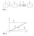
- FIG. 1 is shown schematically the drive train of a motor vehicle. It is in FIG. 1 the distance of the drive train shown, which includes a motor part 1, the rotational energy outputs to a controllable clutch 2, which drives a driven part 3 on the output side in the direction of rotation.
- the driven part 3 in turn acts on a transmission 4, which is connected via a spring-elastic connecting element 5 with a traction part 6, which finally makes contact with the outside world of the motor vehicle.
- a slip occurs in the clutch 2
- undesirable speed vibrations can occur due to the resilient element 5 on the output side of the clutch.
- the frequency and the extent depend in particular on the clutch capacity of the clutch 2, the moment of inertia on the output side 3, the transmission ratio of the transmission 4 and the spring stiffness of the connecting element 5.
- FIG. 2 the situation when starting up is shown.
- the time t is plotted on the horizontal axis to the right, and the speed n is plotted upward on the vertical axis.
- the speed curve n1 describes the course of the speed on the engine side 1
- the speed curve n6 describes the course of the speed on the traction side 6.
- the speed curves n3 and n3 ' describe the speed on the output side 3, wherein the curve n3' the speed curve during a startup describes in the prior art.
- the curve n3 ' has a certain ripple, which results from a rotational speed superimposed on the linear speed increase.
- the aim of the present invention is to reduce this ripple on the output side of the clutch 2, so that the ideal curve n3 for the speed curve on the output side 3 of the clutch 2 results.
- FIG. 3 The block diagram shown comprises two control loops, an inner loop and an outer loop. Both control circuits generate in sum a control signal u for the clutch 2, wherein the control signal u affects the behavior of both the motor side 1 and the output side 3. These two sections 1 and 3 deliver at the exit in the in FIG. 3 illustrated diagram, the two speeds n1 as the speed of the motor side 1 and n3 as the speed of the output side. 3
- the outer control loop carries the engine speed n1 and comprises a first control block R1, the input of which is acted on by the difference between an engine speed command or desired motor speed x1 and the actual motor speed n1.
- the output signal of the first control block R1 is added to the output of a first disturbance variable input S1, whose input is also acted upon by the desired motor speed S1.
- the sum of the output signals of the first control block R1 and the first Störssenscrien S1 is applied to a summer 7, in which the output signal of the second inner loop is summed and at whose output the manipulated variable u for the clutch 2 is applied.
- the inner control loop which also acts on a positive input of the summing 7 and thus also by means of the control signal u generated by the summing 7 on the clutch 2.
- Core of the inner control loop form the two filters F3 and F4, wherein the filter F3 includes a model of the real distance 3, which emulates the behavior of the output side 3 as well as possible with ideal execution of all components involved.
- the filter F4 includes a model of an idealized segment 3 that mimics the behavior of the output side 3 on the assumption that the segment 3 behaves in a manner that is more advantageous for the behavior of the drivetrain. This means, in particular, that the model of the idealized section 3 in filter F4 is less prone to oscillations or has a higher attenuation than the model in filter F3.
- the filter F4 is acted upon by both the speed signal n3 of the output side 3 and the output signal of a combiner K, which is acted on the input side with the control signal u and characteristic quantities of the distance 3.
- the filter F4 continuously calculates target values for the rotational speed n3 of the path 3 from the input variables using the model of the idealized path 3, these target values representing the values which the idealized path would deliver under the prevailing conditions.
- the filter F3 is supplied with the output signal of the combiner K and the speed signal n3 of the output side 3 filtered by means of a high-pass filter F1.
- the high pass filter F1 is optional and may be omitted.
- the filter F3 delivers two signals.
- the filter F3 continuously supplies actual values of the rotational speed n3 of the path 3 at a second control block R2, these actual values representing the values which the modeled route 3 supplies or would deliver the route 3 in the case of ideal execution.
- the second control block R2 calculates the difference for the rotational speed n3 on the basis of the output signals of the filters F3 and F4 and, depending therefrom, generates an output signal which acts additively on the adder 7 and thus on the actuator u.
- the second control block R2 thus does not control the speed n3 of the path 3, but the behavior of the model of the path in the filter F3 the behavior of the model of the idealized path in the filter F4 and thus changes the behavior of the track 3 such that they are like the in the filter F4 modeled idealized route behaves. In this way, by engaging the clutch 2, the distance 3 can be effectively damped. Since the model is more damped in the filter F4, the inner loop essentially affects a higher-frequency frequency range.
- the model in filter F3 is fundamentally predetermined in nature, with variable parameters being provided in the model. These parameters are generated by the filter F5, which also includes a model of the path 3 and is acted upon by the output signal of the combiner K and the speed signal n3 filtered by the high-pass filter F1. Based on the input signals, the filter F5 calculates the parameters for the model in the filter F3 in such a way that the model in the filter F3 agrees as well as possible with the real distance 3 in the filter F3. The parameters supplied by the filter F5 pass through the filter F2 before they reach the filter F3.
- the filter F3 also supplies the input signal for a second feedforward control S2, which describes the components in the speed signal n3, which is due to the difference between the behavior of the real track 3 and the model of the track 3 in FIG Filter F3 result.
- the Störehrnaufscrien S2 provides an output signal which acts like the output of the second control block R2 additively to the summing 7 and thus to the control signal u.
- the second disturbance variable application S2 counteracts portions in the rotational speed signal n3, which result from the differences between the real distance 3 and the model in the filter F3.
- the two control circuits are designed so that they act in mutually substantially separate frequency ranges. This means that the inner loop is not adversely affects the control of the engine target speed x1, but substantially only reduces or corrects the unwanted speed vibrations on the output side 3 of the clutch 2.
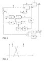
- FIG. 4 is the ratio of the two frequency ranges shown to each other, wherein in the diagram to the right horizontally the frequency f and vertically upwards the ratio of the calculated in the single control loop manipulated variable to the application to the input shown. It can be seen that the region 8 is located in the low-frequency band and is band-limited to higher frequencies, whereas the range 9 is in the upper frequency range and band-limited to lower frequencies.
- the first region 8 is the effective range of the first outer control loop, and the second region 9 is the frequency range in which the inner second control circuit for eliminating the undesirable speed oscillations lies.
Landscapes
- Engineering & Computer Science (AREA)
- Chemical & Material Sciences (AREA)
- Combustion & Propulsion (AREA)
- Mechanical Engineering (AREA)
- Transportation (AREA)
- General Engineering & Computer Science (AREA)
- Automation & Control Theory (AREA)
- Physics & Mathematics (AREA)
- Fluid Mechanics (AREA)
- Hydraulic Clutches, Magnetic Clutches, Fluid Clutches, And Fluid Joints (AREA)
- Control Of Vehicle Engines Or Engines For Specific Uses (AREA)
- Control Of Driving Devices And Active Controlling Of Vehicle (AREA)
Description
- Die vorliegende Erfindung betrifft ein Verfahren bzw. eine Vorrichtung zur Steuerung zweier Regelgrößen in einem Antriebsstrang eines Kraftfahrzeugs.
- Im Kraftfahrzeugbereich werden beispielsweise zunehmend Handschaltgetriebe durch automatische Getriebe bzw. automatisierte Getriebe ersetzt. Die entsprechende Ansteuerung der Kupplung erfolgt in aller Regel über einen Getrieberechner bzw. eine Steuervorrichtung. Dazu wird mit einem Stellglied die aktuelle Kupplungskapazität einer steuerbaren Kupplung zeitabhängig eingestellt. Ziel bisheriger bekannter Kupplungsansteuerungen war es, entweder Differenz- oder Absolutdrehzahlverläufen zu folgen. Um eine gute Regelgüte zu erlangen, ist es notwendig, dass eine definierte Ansteuerung der Kupplung auch eine definierte Änderung der Kupplungskapazität zur Folge hat. Dies bedeutet im Umkehrschluss, dass bei konstanter Ansteuerung der Kupplung sich dessen Kapazität nicht ändern darf. Daher werden an die Fertigungstoleranzen des Stellglieds und der Kupplung große Anforderungen gestellt. Werden diese nicht eingehalten oder durch die Alterung der Bauteile nicht mehr erfüllt, können während der Schlupfphase der Kupplung unerwünschte Momentenänderungen auftreten und unter Umständen Schwingungen im Antriebsstrang angeregt werden.
- Die
EP 1 258 386 A2 offenbart ein Verfahren zur Durchführung eines Anfahrvorgangs bei einem Antriebssystem. Um einen komfortablen Anfahrvorgang zu erreichen, wird zuerst ein Fahreranforderungsmoment ermittelt, welches anschließend verringert als Vorgabemoment zur Ansteuerung des Antriebsmotors verwendet wird. Anschließend wird eine Kupplungsanordnung eingekuppelt und danach das Vorgabemoment wieder bis auf den ursprünglich vom Fahrer angeforderten Wert erhöht. Nachteiligerweise werden dabei jedoch Schwingungen im Antriebsstrang nicht erkannt und auch nicht ausgeregelt. - Weiterhin ist durch die
EP 1 078 805 A1 eine Steuerung für den Antriebsstrang beim Anfahren eines Kraftfahrzeugs beschrieben, wobei mittels einer Erkennungsschaltung die jeweilige Fahrsituation des Fahrzeugs und die Fahrercharakteristik ermittelt werden und bei Anfahren des Kraftfahrzeugs eine Steuereinrichtung für die Kupplung an die ermittelte Fahrsituation und/oder Fahrercharakteristik adaptiv angepasst wird. Auch hier findet eine Erkennung von Schwingungen im Antriebsstrang und deren Ausregelung nachteiligerweise nicht statt. - Die
DE 3937976 A1 offenbart eine Regeleinrichtung nach dem Oberbegriff des Anspruchs 11, bei welcher ein erster Regelkreis vorhanden ist, der aus dem die Differenzdrehzahl als Regelgröße ermittelnden Messwertgeber und aus dem aus Betriebsparametern der Brennkraftmaschine einen ersten Soll-Wert bildenden ersten Soll-Wert-Geber besteht. Diesem ersten Regelkreis ist ein zweiter Regelkreis überlagert, zu dem die die Drehgeschwindigkeitsdifferenzen ermittelnde Sensoreinrichtung und der zweite Soll-Wert-Geber gehören. Der zweite Soll-Wert-Geber kann den Soll-Wert des ersten Soll-Wert-Gebers adaptiv beeinflussen oder ummittelbar auf den Summierer im Sinne einer Erhöhung des Soll-Wertes wirken. - Der vorliegenden Erfindung liegt die Aufgabe zu Grunde, ein Verfahren bzw. eine Vorrichtung zur Regelung zweier Regelgrößen in einem Kraftfahrzeug, insbesondere Regelgrößen eines Antriebsstrangs des Kraftfahrzeugs, wobei die beiden Regelgrößen im Wesentlichen entkoppelt voneinander durch geringen Aufwand an Stellgliedern geregelt werden können.
- Erfindungsgemäß wird diese Aufgabe durch ein Verfahren mit den Merkmalen des Anspruchs 1 bzw. eine Vorrichtung mit den Merkmalen des Anspruchs 11 gelöst. Die Unteransprüche definieren jeweils bevorzugte und vorteilhafte Ausführungsformen der vorliegenden Erfindung.
- Erfindungsgemäß wird eine erste Regelgröße von einem ersten Regelkreis mit einem ersten Regelblock und eine zweite Regelgröße von einem zweiten Regelkreis mit einem zweiten Regelblock geregelt, wobei die beiden Regelkreise in voneinander unterschiedlichen Frequenzbereichen wirksam sind. Auf diese Weise können mit einem sehr geringen Aufwand auf der Stellgliedseite beide Regelgrößen geregelt werden.
- Im Fall der Regelung von Drehzahlschwingungen in einem Antriebsstrang werden zunächst Drehzahlschwingungen in dem Teil des Antriebsstrangs auf der Abtriebsseite der Kupplung ermittelt und durch Stelleingriff auf die Kupplung mittels einer Schwingungsregelung verringert. Durch den Eingriff der Schwindungsregelung bei der Kupplung kann das auf den Antriebsstrang auf der Abtriebsseite der Kupplung wirkende Drehmoment besonders schnell und besonders stark verändert werden, so dass die Regelung wirkungsvoll und schnell auf den zu regelnden Antriebsstrang einwirken kann.
- Die Schwingungsregelung kann auch auf eine zusätzliche Kupplung wirken, die in dem Antriebsstrang vorhanden ist. Eine derartige zusätzliche Kupplung kann insbesondere in einem Automatikgetriebe vorhanden sein und die Verbindung zwischen dem Motor und einem Zweig herstellen können, der ein Drehmoment in den Zweig einspeisen kann, der den Hauptanteil des Drehmoments überträgt. Dabei kann auch vorgesehen sein, dass die Schwingungsregelung bei einer Hauptkupplung und einer zusätzlichen Kupplung jeweils auf die Kupplung wirkt, die sich gerade im Schlupf befindet. Das Umschalten der Einwirkung auf die beiden Kupplungen kann abrupt sein, so dass eine Einwirkung auf eine Kupplung eine Einwirkung auf die andere ausschließt, oder einen fließenden Übergang bilden, bei dem in einem Zwischenzustand beide Kupplungen mit einem Stellsignal beaufschlagt werden, wobei auch vorgesehen sein kann, dass das Stellsignal für eine erste Kupplung von einem Regelkreis erzeugt wird und das Stellsignal für die andere Kupplung aus dem Stellsignal für die erste Kupplung berechnet wird.
- Anstelle der zusätzlichen Kupplung kann auch ein Elektroantrieb in Abhängigkeit eines von der Regelung erzeugten Stellsignals angesteuert werden, der ähnlich wie die zusätzliche Kupplung ein zusätzliches Drehmoment auf den Antriebsstrang an der Abtriebsseite der Hauptkupplung aufbringen kann. Allgemein kann anstelle der zusätzlichen Kupplung ein anderes Stellglied verwendet werden, das das zusätzliche Einbringen eines Drehmoments auf der Abtriebsseite der Kupplung ermöglicht, wie beispielsweise Synchronisiereinrichtungen in einem Getriebe. Für die Ansteuerung der Alternativen zu einer zusätzlichen Kupplung gilt das Gleiche wie für die Ansteuerung der zusätzlichen Kupplung.
- Das Einwirken auf eine zusätzliche Kupplung ist besonders in den Situationen sinnvoll, in denen eine Hauptkupplung geschlossen ist.
- Vorteilhafterweise ist die Schwingungsregelung wenigstens einer weiteren Regelung zugeordnet, welche ebenso mittels Stelleingriff auf die Kupplung einwirkt. Die weitere Regelung kann beispielsweise eine Regelung zur Führung der Motordrehzahl umfassen. Weiterhin kann die Kupplung von einer Regelung zur Führung des von der Kupplung übertragenen Drehmoments beaufschlagt werden.
- Wenn mehrere Regelkreise auf die Kupplung einwirken, wird die Schwingungsregelung vorteilhafterweise so eingerichtet, dass sie den anderen Regelkreisen derart überlagert ist, dass diese wenig oder gar nicht beeinflusst werden.
- Um die Schwingungsregelung ohne Beeinflussung anderer Regelkreise implementieren zu können, kann vorgesehen sein, dass der Frequenzbereich im Schwingungsregelkreis bandbegrenzt ist. Dazu kann grundsätzlich an beliebiger Stelle im Schwingungsregelkreis eine Frequenzbandbegrenzung der übertragenen Signale vorgenommen werden. Dies kann beispielsweise bei der Berechnung der Stelleingriffe bzw. eines Stellsignals sein. Weiterhin kann auch bei der Ermittlung der Ist-Größe bzw. der durch Regelung zu verringernden Drehzahlschwingungen eine Bandbegrenzung vorgenommen werden.
- Vorzugsweise wird der Schwingungsregelkreis derart bandbegrenzt, dass er nicht in derartigen Frequenzbereichen wirksam ist, in denen bereits andere Regelungen wirken, denen der Schwingungsregelkreis zugeordnet ist. Dabei kann entweder ausgenutzt werden, dass die anderen Regelkreise von ihrer Natur her bandbegrenzt sind oder können die anderen Regelkreise gezielt bandbegrenzt werden. Da die Drehzahlschwingungen im Vergleich zu den anderen Stelleingriffen in der Regel höherfrequent sind, werden die Frequenzbereiche vorteilhafterweise derart aufgeteilt, dass die Schwingungsregelung in einem Frequenzbereich wirkt, der oberhalb der Frequenzbereiche liegt, in denen der wenigstens eine zugeordnete weitere Regelkreis wirkt.
- Zum Ermitteln der Drehzahlschwingungen auf der Abtriebsseite der Kupplung bieten sich verschiedene Möglichkeiten an. Zum Einen kann mit einem einfachen Filter, das eine Hochpasscharakteristik besitzt, ein Maß für Drehzahlschwingungen ermittelt werden. Dies setzt jedoch voraus, dass die unerwünschten Drehzahlschwingungen in einem Frequenzbereich auftreten, der mit ausreichendem Abstand oberhalb der Frequenzbereiche liegt, in denen erwünschte Veränderungen der Drehzahl liegen.
- Vorteilhafterweise wird daher zur Unterscheidung von unerwünschten Drehzahlschwingungen und erwünschten Drehzahlveränderungen ein Beobachter eingeführt, der ein Modell zumindest eines Teils des Antriebsstrangs umfasst. Das Modell im Beobachter beschreibt dabei das ideale Verhalten des Antriebsstrangs ohne die bei einem realen Antriebsstrang vorhandenen Fehler, die zu den unerwünschten Drehzahlschwingungen führen können. Das Modell im Beobachter wird nun der realen Entsprechung im Antriebsstrang nachgeführt, indem es den gleichen Einwirkungen ausgesetzt wird. Dazu wird es mit den auf die reale Entsprechung im Antriebsstrang wirkenden Stelleingriffen und beeinflussenden Umgebungseinflüssen beaufschlagt. Dies bewirkt, dass sich das Modell so verhält wie der nachgestellte Teil des Antriebsstrangs, wobei das Modell jedoch die Verhaltensmuster nicht zeigt, die beim realen Antriebsstrang auf Fehler oder allgemeine Unzulänglichkeiten zurückgehen, wie beispielsweise Abnutzung, überschrittene Toleranzgrenzen usw., die im Modell nicht berücksichtigt sind. Durch den Vergleich des Modells im Beobachter und des Verhaltens der realen Strecke bzw. des nachmodulierten Teils des Antriebsstrangs können somit die erwünschten Verhaltensteile, die sich auf Grund der üblichen Regelung ergeben, von den unerwünschten Verhaltensteilen getrennt werden, die sich auf Grund von Fehlern oder nachteiligen Veränderungen im Antriebsstrang ergeben haben. Gleiches gilt selbstverständlich auch für die unerwünschten Drehzahlschwingungen. In diesem Fall können auch unerwünschte Drehzahlschwingungen erkannt und ausgeregelt werden, die in den gleichen Frequenzbereich fallen wie Drehzahländerungen, die von einer nebengeordneten Regelung tatsächlich erwünscht waren.
- Die Erfindung wird nachfolgend anhand eines bevorzugten Ausführungsbeispiels unter Bezugnahme auf die beigefügten Zeichnungen näher erläutert.
-
Figur 1 zeigt schematisch einen Antriebsstrang eines Kraftfahrzeugs, -
Figur 2 zeigt schematisch vier innerhalb des Antriebsstrangs auftretende Drehzahlverläufe, -
Figur 3 zeigt ein Blockdiagramm einer Regelung zur Verringerung von Drehzahlschwingungen innerhalb des Antriebsstrangs gemäß dem Ausführungsbeispiel der vorliegenden Erfindung mit zugeordneter Regelung der Motordrehzahl, und -
Figur 4 zeigt die Frequenzbereiche, in denen die beiden Regelungen gemäßFigur 3 wirksam sind. - In
Figur 1 ist schematisch der Antriebsstrang eines Kraftfahrzeugs dargestellt. Dabei ist inFigur 1 die Strecke des Antriebsstrangs dargestellt, die einen Motorteil 1 umfasst, der Drehenergie an eine steuerbare Kupplung 2 abgibt, welche auf der Abtriebsseite in Drehrichtung einen Abtriebsteil 3 antreibt. Der Abtriebsteil 3 wirkt wiederum auf ein Getriebe 4, welches über ein federelastisches Verbindungselement 5 mit einem Traktionsteil 6 verbunden ist, welcher schließlich den Kontakt zur Außenwelt des Kraftfahrzeugs herstellt. Insbesondere wenn bei der Kupplung 2 ein Schlupf auftritt, können auf Grund des federelastischen Elements 5 auf der Abtriebsseite der Kupplung 2 unerwünschte Drehzahlschwingungen auftreten. Die Frequenz und das Ausmaß richten sich insbesondere nach der Kupplungskapazität der Kupplung 2, dem Trägheitsmoment auf der Abtriebsseite 3, dem Übersetzungsverhältnis des Getriebes 4 und der Federsteifigkeit des Verbindungselements 5. - In
Figur 2 ist die Situation beim Anfahren dargestellt. Dabei ist in dem dargestellten Diagramm auf der horizontalen Achse nach rechts die Zeit t und nach oben auf der senkrechten Achse die Drehzahl n aufgetragen. Im dargestellten Diagramm sind vier Drehzahlverläufe dargestellte. Der Drehzahlverlauf n1 beschreibt den Verlauf der Drehzahl auf der Motorseite 1 und der Drehzahlverlauf n6 beschreibt den Verlauf der Drehzahl auf der Traktionsseite 6. Die Drehzahlverläufe n3 und n3' beschreiben die Drehzahl auf der Abtriebsseite 3, wobei der Verlauf n3' den Drehzahlverlauf bei einem Anfahrvorgang nach dem Stand der Technik beschreibt. Der Verlauf n3' weist eine gewisse Welligkeit auf, die von einer dem linearen Drehzahlanstieg überlagerten Drehzahlschwingung herrührt. Ziel der vorliegenden Erfindung ist es, diese Welligkeit auf der Abtriebsseite der Kupplung 2 zu verringern, so dass sich der ideale Verlauf n3 für den Drehzahlverlauf auf der Abtriebsseite 3 der Kupplung 2 ergibt. - Dazu wird ein Regelungsverfahren eingesetzt, das schematisch in
Figur 3 dargestellt ist. - Das in
Figur 3 dargestellte Blockschaltdiagramm umfasst zwei Regelkreise, einen inneren Regelkreis und einen äußeren Regelkreis. Beide Regelkreise erzeugen in Summe ein Stellsignal u für die Kupplung 2, wobei das Stellsignal u sich auf das Verhalten sowohl der Motorseite 1 als auch der Abtriebsseite 3 auswirkt. Diese beiden Streckenabschnitte 1 und 3 liefern am Ausgang in dem inFigur 3 dargestellten Diagramm die beiden Drehzahlen n1 als Drehzahl der Motorseite 1 und n3 als Drehzahl der Abtriebsseite 3. - Der äußere Regelkreis führt die Motordrehzahl n1 und umfasst einen ersten Regelblock R1, dessen Eingang mit der Differenz zwischen einer Motordrehzahlführungsgröße bzw. Motor-Soll-Drehzahl x1 und der Motor-Ist-Drehzahl n1 beaufschlagt wird. Das Ausgangssignal des ersten Regelblocks R1 addiert sich zu dem Ausgang einer ersten Störgrößenaufschaltung S1, deren Eingang ebenfalls von der Motor-Soll-Drehzahl S1 beaufschlagt wird. Die Summe der Ausgangssignale des ersten Regelblocks R1 und der ersten Störgrößenaufschaltung S1 wird auf ein Summierglied 7 gegeben, in dem das Ausgangssignal des zweiten inneren Regelkreises aufsummiert wird und an dessen Ausgang die Stellgröße u für die Kupplung 2 anliegt.
- Anschließend wird der innere Regelkreis beschrieben, der ebenfalls auf einen positiven Eingang des Summierglieds 7 und somit mittels des vom Summierglied 7 erzeugten Stellsignals u ebenfalls auf die Kupplung 2 wirkt.
- Kern des inneren Regelkreises bilden die beiden Filter F3 und F4, wobei das Filter F3 ein Modell der realen Strecke 3 beinhaltet, das das Verhalten der Abtriebsseite 3 bei idealer Ausführung aller beteiligten Komponenten möglichst gut nachbildet. Das Filter F4 beinhaltet ein Modell einer idealisierten Strecke 3, das das Verhalten der Abtriebsseite 3 unter der Annahme nachbildet, dass die Strecke 3 sich auf eine für das Verhalten des Antriebstrangs vorteilhaftere Weise verhält. Dies bedeutet insbesondere, dass das Modell der idealisierten Strecke 3 in Filter F4 weniger zu Schwingungen neigt bzw. eine höhere Dämpfung aufweist als das Modell in Filter F3.
- Das Filter F4 wird sowohl von dem Drehzahlsignal n3 der Abtriebseite 3 als auch dem Ausgangssignal eines Kombinierglieds K beaufschlagt, das eingangsseitig mit dem Stellsignal u und Eigenschaftsgrößen der Strecke 3 beaufschlagt wird. Das Filter F4 berechnet aus den Eingangsgrößen mit Hilfe des Modells der idealisierten Strecke 3 laufend Soll-Werte für die Drehzahl n3 der Strecke 3, wobei diese Soll-Werte die Werte darstellen, die die idealisierte Strecke unter den herrschenden Bedingungen liefern würde.
- Das Filter F3 wird mit dem Ausgangssignal des Kombinierglieds K und dem mittels eines Hochpassfilter F1 gefilterten Drehzahlsignal n3 der Abtriebsseite 3 beaufschlagt. Das Hochpassfilter F1 ist optional und kann auch weggelassen werden. An der Ausgangsseite liefert das Filter F3 zwei Signale. Zum einen liefert das Filter F3 an einem zweiten Regelblock R2 laufend Ist-Werte der Drehzahl n3 der Strecke 3, wobei diese Ist-Werte die Werte darstellen, die die modellierte Strecke 3 liefert bzw. die Strecke 3 bei idealer Ausführung liefern würde. Der zweite Regelblock R2 berechnet anhand der Ausgangssignale der Filter F3 und F4 die Differenz für die Drehzahl n3 und erzeugt davon abhängig ein Ausgangssignal, welches additiv auf das Addierglied 7 und somit auf das Stellglied u wirkt. Der zweite Regelblock R2 regelt somit nicht die Drehzahl n3 der Strecke 3, sondern das Verhalten des Modells der Strecke im Filter F3 dem Verhalten des Modells der idealisierten Strecke im Filter F4 nach und ändert somit das Verhalten der Strecke 3 derart, dass diese sich wie die im Filter F4 modellierte idealisierte Strecke verhält. Auf diese Weise kann durch Eingriff bei der Kupplung 2 die Strecke 3 wirkungsvoll gedämpft werden. Da das Modell im Filter F4 stärker gedämpft ist, wirkt sich der innere Regelkreis im Wesentlichen in einem höherfrequenten Frequenzbereich aus.
- Das Modell im Filter F3 ist grundsätzlich seiner Art nach vorgegeben, wobei in dem Modell veränderliche Parameter vorgesehen sind. Diese Parameter werden von dem Filter F5 erzeugt, das ebenfalls ein Modell der Strecke 3 beinhaltet und von dem Ausgangssignal des Kombinierglieds K und dem mittels des Hochpassfilter F1 gefilterten Drehzahlsignal n3 beaufschlagt wird. Das Filter F5 berechnet anhand der Eingangssignale die Parameter für das Modell im Filter F3 derart, dass das Modell im Filter F3 dem Grundsatz nach möglichst gut mit der realen Strecke 3 übereinstimmt. Die vom Filter F5 gelieferten Parameter durchlaufen vorher noch das Filter F2, bevor sie zum Filter F3 gelangen.
- Das Filter F3 liefert neben den Ist-Werten für den zweiten Regelblock R2 auch das Eingangssignal für eine zweite Störgrößenaufschaltung S2, welches die Anteile im Drehzahlsignal n3 beschreibt, die sich aufgrund der Differenz zwischen dem Verhalten der realen Strecke 3 und dem Modell der Strecke 3 im Filter F3 ergeben. Die Störgrößenaufschaltung S2 liefert ein Ausgangssignal, das wie das Ausgangssignal des zweiten Regelblocks R2 additiv auf das Summierglied 7 und somit auf das Stellsignal u wirkt. Auf diese Weise wirkt die zweite Störgrößenaufschaltung S2 Anteilen im Drehzahlsignal n3 entgegen, die sich aufgrund der Unterschiede zwischen der realen Strecke 3 und dem Modell im Filter F3 ergeben.
- Die beiden Regelkreise sind dabei so ausgelegt, dass sie in voneinander im Wesentlichen getrennten Frequenzbereichen wirken. Dies bedeutet, dass der innere Regelkreis sich nicht nachteilig auf die Regelung der Motorsolldrehzahl x1 auswirkt, sondern im Wesentlichen nur die unerwünschten Drehzahlschwingungen auf der Abtriebsseite 3 der Kupplung 2 reduziert bzw. ausregelt.
- In
Figur 4 ist das Verhältnis der beiden Frequenzbereiche zueinander dargestellt, wobei in dem Diagramm nach rechts horizontal die Frequenz f und senkrecht nach oben das Verhältnis des in dem einzelnen Regelkreis berechneten Stellgrößenanteils zu der Beaufschlagung am Eingang dargestellt. Dabei ist zu erkennen, dass der Bereich 8 im Niederfrequenten liegt und zu höheren Frequenzen hin nach oben bandbegrenzt ist, wohingegen der Bereich 9 im oberen Frequenzbereich liegt und zu tieferen Frequenzen bandbegrenzt ist. Der erste Bereich 8 ist der Wirkungsbereich des ersten äußeren Regelkreises und der zweite Bereich 9 ist der Frequenzbereich, in dem der innere zweite Regelkreis zur Beseitigung der unerwünschten Drehzahlschwingungen liegt. -
- 1
- Motorseite
- 2
- Kupplung
- 3
- Abtriebsseite
- 4
- Getriebe
- 5
- federelastisches Verbindungselement
- 6
- Traktionsseite
- n
- Drehzahl
- n1
- Motordrehzahl
- n3, n3'
- Drehzahl auf der Abtriebsseite
- n6
- Drehzahl auf der Traktionsseite
- 7
- Summierglied
- 8
- Frequenzbereich des Motordrehzahlregelkreises
- 9
- Frequenzbereich des Drehzahlschwingungsregelkreises
- K
- Kombinierglied
- R1
- erster Regelblock
- R2
- zweiter Regelblock
- S1
- erste Störgrößenaufschaltung
- S2
- zweite Störgrößenaufschaltung
- F1, F2, F3, F4, F5
- Filter
- x1
- Motordrehzahlführungsgröße
Claims (12)
- Verfahren zur Regelung einer ersten Regelgröße und einer zweiten Regelgröße in einem Antriebsstrang (1-6) eines Kraftfahrzeugs, wobei für die erste Regelgröße ein erster eigener Regelkreis und für die zweite Regelgröße ein zweiter eigener Regelkreis vorgesehen ist,
dadurch gekennzeichnet, dass der erste Regelkreis einen ersten Regelblock (R1) zum Regeln der ersten Regelgröße und der zweite Regelkreis einen zweiten Regelblock (R2) zum Regeln der zweiten Regelgröße umfasst, wobei die beiden Regelkreise derart eingerichtet sind, dass beide Regelkreise überlagert auf eine Kupplung (2) des Antriebsstrangs wirken und ihr Übertragungsverhalten in Bezug auf die Frequenz jeweils derart unterschiedlich ist, dass sie in voneinander im Wesentlichen getrennten Frequenzbereichen wirken. - Verfahren nach Anspruch 1, dadurch gekennzeichnet, dass die beiden Regelkreise in jeweils einem von zwei Frequenzbereichen wirksam sind, die sich voneinander unterscheiden.
- Verfahren nach Anspruch 1 oder 2, dadurch gekennzeichnet, dass die beiden Regelgrößen Größen zur Steuerung des Antriebsstrangs (1-6) des Kraftfahrzeugs mit einem Motor (1) und wenigstens einer steuerbaren Kupplung (2) als Stellglied sind und eine Regelgröße ein Maß für Drehzahlschwingungen eines Abschnitts des Antriebsstrangs an der Abtriebsseite der Kupplung (2) ist und derart geregelt wird, dass Drehzahlschwingungen mittels einer Schwingungsregelung durch Stelleingriff auf die Kupplung verringert werden.
- Verfahren nach einem der vorhergehenden Ansprüche, dadurch gekennzeichnet, dass ein Regelkreis eine Regelung zur Führung der Motordrehzahl (n1) umfasst.
- Verfahren nach einem der vorhergehenden Ansprüche, dadurch gekennzeichnet, dass ein Regelkreis eine Regelung zur Führung des von der Kupplung (2) übertragenen Drehmoments umfasst.
- Verfahren nach einem der vorhergehenden Ansprüche, dadurch gekennzeichnet, dass zur Erreichung eines in Bezug auf die Frequenz unterschiedlichen Übertragungsverhaltens der Regelkreise das Frequenzspektrum von Signalen in einem Regelkreis mittels einer Hochpassfilterung oder einer Bandpassfilterung begrenzt werden.
- Verfahren nach Anspruch 6, dadurch gekennzeichnet, dass ein Regelkreis der Verringerung von Drehzahlschwingungen in einem Abschnitt des Antriebsstrangs eines Kraftfahrzeugs auf der Abtriebsseite (3) der Kupplung (2) dient und die Begrenzung des Frequenzspektrums bei der Ermittlung eines Maßes für Drehzahlschwingungen und/oder bei der Erzeugung eines Stelleingriffs für die Kupplung (2) durchgeführt wird.
- Verfahren nach einem der vorhergehenden Ansprüche, dadurch gekennzeichnet, dass ein Regelkreis einen Beobachter (F3) mit einem Modell zumindest eines Teils der zu regelnden Strecke umfasst und Ist-Werte der Regelgröße durch Auswertungen von im Modell auftretenden Signalen ermittelt werden.
- Verfahren nach einem der vorhergehenden Ansprüche, dadurch gekennzeichnet, dass ein Regelkreis einen Beobachter (F4) mit einem idealisierten Modell zumindest eines Teils der zu regelnden Strecke umfasst und Soll-Werte der Regelgröße durch Auswertungen von im Modell auftretenden Signalen ermittelt werden.
- Verfahren nach Anspruch 8 und 9, dadurch gekennzeichnet, dass die Stellgröße für die Kupplung (2) derart in Abhängigkeit der Ist-Werte und der Soll-Werte beeinflusst wird, dass das Verhalten einer Strecke (3) dem des idealisierten Modells (F4) nahe kommt.
- Vorrichtung zur Regelung einer ersten Regelgröße und einer zweiten Regelgröße in einem Antriebsstrang (1-6) eines Kraftfahrzeugs, wobei für die erste Regelgröße ein erster eigener Regelkreis und für die zweite Regelgröße ein zweiter eigener Regelkreis vorgesehen ist, wobei die Vorrichtung Signalerfassungsmittel und Signalverarbeitungsmittel umfasst, dadurch gekennzeichnet, dass der erste Regelkreis einen ersten Regelblock (R1) zum Regeln der ersten Regelgröße und der zweite Regelkreis einen zweiten Regelblock (R2) zum Regeln der zweiten Regelgröße umfasst, wobei die beiden Regelkreise derart eingerichtet sind, dass beide Regelkreise überlagert auf eine Kupplung (2) des Antriebsstrangs wirken und ihr Übertragungsverhalten in Bezug auf die Frequenz jeweils derart unterschiedlich ist, dass sie in voneinander im Wesentlichen getrennten Frequenzbereichen wirken.
- Vorrichtung nach Anspruch 11, dadurch gekennzeichnet, dass die Vorrichtung zur Durchführung eines Verfahrens nach einem der Ansprüche 1 bis 10 eingerichtet ist.
Applications Claiming Priority (3)
| Application Number | Priority Date | Filing Date | Title |
|---|---|---|---|
| DE10260838A DE10260838A1 (de) | 2002-12-23 | 2002-12-23 | Verfahren und Vorrichtung zur Steuerung einer Kupplung innerhalb eines Kraftfahrzeugtriebstrangs |
| DE10260838 | 2002-12-23 | ||
| PCT/EP2003/014076 WO2004058533A1 (de) | 2002-12-23 | 2003-12-11 | Verfahren und vorrichtung zur steuerung einer kupplung innerhalb eines kraftfahrzeugtriebstrangs |
Publications (2)
| Publication Number | Publication Date |
|---|---|
| EP1578635A1 EP1578635A1 (de) | 2005-09-28 |
| EP1578635B1 true EP1578635B1 (de) | 2010-03-17 |
Family
ID=32519354
Family Applications (1)
| Application Number | Title | Priority Date | Filing Date |
|---|---|---|---|
| EP03785792A Expired - Lifetime EP1578635B1 (de) | 2002-12-23 | 2003-12-11 | Verfahren und vorrichtung zur steuerung einer kupplung innerhalb eines kraftfahrzeugtriebstrangs |
Country Status (4)
| Country | Link |
|---|---|
| EP (1) | EP1578635B1 (de) |
| AT (1) | ATE461089T1 (de) |
| DE (2) | DE10260838A1 (de) |
| WO (1) | WO2004058533A1 (de) |
Families Citing this family (5)
| Publication number | Priority date | Publication date | Assignee | Title |
|---|---|---|---|---|
| FR2862732B1 (fr) * | 2003-11-26 | 2009-07-31 | Volkswagen Ag | Procede et dispositif de regulation de deux grandeurs reglees dans un vehicule automobile |
| US8142328B2 (en) * | 2007-07-05 | 2012-03-27 | Schaeffler Technologies AG & Co. KG | Method for controlling a starting clutch |
| DE102010029706A1 (de) * | 2010-06-04 | 2011-12-08 | Robert Bosch Gmbh | Verfahren und Vorrichtung zur Erkennung von ungewollten Triebstrangreaktionen eines Kraftfahrzeuges mit wenigstens einem Antriebsaggregat |
| SE542318C2 (en) * | 2018-03-01 | 2020-04-07 | Scania Cv Ab | Method and control arrangement for controlling a rotational speed of a power source of a vehicle |
| DE102020119552A1 (de) | 2020-07-24 | 2022-01-27 | Audi Aktiengesellschaft | Verfahren zur Regelung eines Antriebsstrangs eines Kraftfahrzeugs, Regelungseinrichtung und Kraftfahrzeug |
Family Cites Families (7)
| Publication number | Priority date | Publication date | Assignee | Title |
|---|---|---|---|---|
| US4457411A (en) * | 1980-06-02 | 1984-07-03 | Mitsubishi Jidosha Kogyo Kabushiki Kaisha | Torque transmission device |
| DE3937976A1 (de) * | 1988-11-17 | 1990-05-23 | Zahnradfabrik Friedrichshafen | Verfahren zur regelung einer kupplung |
| JP3237419B2 (ja) * | 1994-10-21 | 2001-12-10 | トヨタ自動車株式会社 | 車両用クラッチ制御装置 |
| DE59906521D1 (de) * | 1999-08-24 | 2003-09-11 | Siemens Ag | Steuerung für den Antriebsstrang beim Anfahren eines Kraftfahrzeugs |
| DE10291374D2 (de) * | 2001-04-02 | 2004-04-29 | Luk Lamellen & Kupplungsbau | Verfahren zur Steuerung einer automatisierten Kupplung |
| DE10124656A1 (de) * | 2001-05-18 | 2002-11-21 | Zf Sachs Ag | Verfahren zur Durchführung eines Anfahrvorgangs bei einem Antriebssystem |
| DE10225285A1 (de) * | 2001-06-13 | 2002-12-19 | Luk Lamellen & Kupplungsbau | Verfahren und ein System zum Regeln des Drehmomentübertragungsvermögens einer reibschlüssig Drehmoment übertragenden Baugruppe |
-
2002
- 2002-12-23 DE DE10260838A patent/DE10260838A1/de not_active Withdrawn
-
2003
- 2003-12-11 WO PCT/EP2003/014076 patent/WO2004058533A1/de not_active Ceased
- 2003-12-11 EP EP03785792A patent/EP1578635B1/de not_active Expired - Lifetime
- 2003-12-11 AT AT03785792T patent/ATE461089T1/de not_active IP Right Cessation
- 2003-12-11 DE DE50312538T patent/DE50312538D1/de not_active Expired - Lifetime
Also Published As
| Publication number | Publication date |
|---|---|
| WO2004058533A1 (de) | 2004-07-15 |
| ATE461089T1 (de) | 2010-04-15 |
| DE10260838A1 (de) | 2004-07-15 |
| EP1578635A1 (de) | 2005-09-28 |
| DE50312538D1 (de) | 2010-04-29 |
Similar Documents
| Publication | Publication Date | Title |
|---|---|---|
| DE10237793B4 (de) | Vorrichtung zur Steuerung einer zwischen einem Motor und einem Getriebe eines Kraftfahrzeuges angeordneten, automatisierten Reibungskupplung | |
| DE19814186B4 (de) | Fahrzeugverfolgung-Steuervorrichtung | |
| DE112008001539B4 (de) | Verfahren und Vorrichtung zum Regeln des Schlupfes einer Fahrzeugkupplung | |
| WO2015158342A2 (de) | Verfahren zur auslegung eines softwaretilgers einer kupplungssteuerung und softwaretilger zur dämpfung von rupfschwingungen | |
| DE102010029937A1 (de) | Verfahren und Vorrichtung zum Reduzieren von Schwingungen auf einer Abtriebswelle eines Antriebsmotors | |
| EP2321166B1 (de) | Vorrichtung und verfahren zum erkennen und reduzieren einer störschwingung bei einem fahrzeug | |
| EP0768455B1 (de) | Verfahren und Vorrichtung zur Steuerung einer Brennkraftmaschine | |
| EP1578635B1 (de) | Verfahren und vorrichtung zur steuerung einer kupplung innerhalb eines kraftfahrzeugtriebstrangs | |
| DE102023127206A1 (de) | System und Verfahren zum Koordinieren von Spielquerungsdurchläufen bei mehrachsigen elektrifizierten Antriebssträngen | |
| EP0473914B1 (de) | System zur Regelung eines Stellwerks in einem Kraftfahrzeug | |
| EP1042137B1 (de) | Verfahren und vorrichtung zur steuerung der geschwindigkeit eines fahrzeugs | |
| EP1279851B1 (de) | Verfahren zum Steuern einer automatischen Kraftfahrzeugkupplung | |
| DE10116544C1 (de) | Betätigungssystem für die Kupplung eines mit einem automatisierten Schaltgetriebe versehenen Kraftfahrzeugantriebs und Verfahren zum Steuern eines solchen Betätigungssystems | |
| DE10301869A1 (de) | Verfahren zur Schwingungsdämpfung eines Antriebsstrangs und Antriebsstrang | |
| DE102017003033B4 (de) | Verfahren zur Verarbeitung von Signalen und Signalfilter | |
| DE102016006213A1 (de) | Verfahren zur Durchführung eines automatischen Fahrmanövers eines Fahrzeugs und Fahrzeug | |
| DE102010052818A1 (de) | Verfahren zur Ansteuerung einer Kupplung | |
| DE102004054909A1 (de) | Verfahren und Vorrichtung zur Regelung zweier Regelgrößen in einem Kraftfahrzeug | |
| WO2022238059A1 (de) | STEUERVORRICHTUNG ZUM BETRIEB EINES STRAßENGEKOPPELTEN ALLRADFAHRZEUGES | |
| DE102018126877B4 (de) | Anti-Ruckel-Eingriff | |
| DE19946905B4 (de) | Antriebsschlupfregelsystem | |
| DE102006037838A1 (de) | Verfahren zur Kupplungssteuerung | |
| EP1435474B1 (de) | Verfahren zur Schwingungsdämpfung eines Antriebsstranges und Antriebsstrang | |
| DE102023001846B4 (de) | Verfahren zur Einstellung einer Dämpfkraft eines Stoßdämpfers eines Fahrzeugs | |
| DE10340400B4 (de) | Verfahren und Vorrichtung zur Dämpfung von niederfrequenten Lastschwingungen bei einem geregelten Antrieb |
Legal Events
| Date | Code | Title | Description |
|---|---|---|---|
| PUAI | Public reference made under article 153(3) epc to a published international application that has entered the european phase |
Free format text: ORIGINAL CODE: 0009012 |
|
| 17P | Request for examination filed |
Effective date: 20050725 |
|
| AK | Designated contracting states |
Kind code of ref document: A1 Designated state(s): AT BE CH CY DE DK ES FI FR GB GR HU IE IT LI LU MC NL PT RO SE TR |
|
| 17Q | First examination report despatched |
Effective date: 20070524 |
|
| GRAP | Despatch of communication of intention to grant a patent |
Free format text: ORIGINAL CODE: EPIDOSNIGR1 |
|
| RIC1 | Information provided on ipc code assigned before grant |
Ipc: B60W 10/02 20060101AFI20091006BHEP Ipc: B60W 10/04 20060101ALI20091006BHEP |
|
| GRAS | Grant fee paid |
Free format text: ORIGINAL CODE: EPIDOSNIGR3 |
|
| GRAA | (expected) grant |
Free format text: ORIGINAL CODE: 0009210 |
|
| AK | Designated contracting states |
Kind code of ref document: B1 Designated state(s): AT BE CH CY DE DK ES FI FR GB GR HU IE IT LI LU MC NL PT RO SE TR |
|
| REG | Reference to a national code |
Ref country code: GB Ref legal event code: FG4D Free format text: NOT ENGLISH |
|
| REG | Reference to a national code |
Ref country code: CH Ref legal event code: EP |
|
| REG | Reference to a national code |
Ref country code: IE Ref legal event code: FG4D |
|
| REF | Corresponds to: |
Ref document number: 50312538 Country of ref document: DE Date of ref document: 20100429 Kind code of ref document: P |
|
| REG | Reference to a national code |
Ref country code: NL Ref legal event code: VDEP Effective date: 20100317 |
|
| PG25 | Lapsed in a contracting state [announced via postgrant information from national office to epo] |
Ref country code: FI Free format text: LAPSE BECAUSE OF FAILURE TO SUBMIT A TRANSLATION OF THE DESCRIPTION OR TO PAY THE FEE WITHIN THE PRESCRIBED TIME-LIMIT Effective date: 20100317 |
|
| REG | Reference to a national code |
Ref country code: IE Ref legal event code: FD4D |
|
| PG25 | Lapsed in a contracting state [announced via postgrant information from national office to epo] |
Ref country code: ES Free format text: LAPSE BECAUSE OF FAILURE TO SUBMIT A TRANSLATION OF THE DESCRIPTION OR TO PAY THE FEE WITHIN THE PRESCRIBED TIME-LIMIT Effective date: 20100628 Ref country code: GR Free format text: LAPSE BECAUSE OF FAILURE TO SUBMIT A TRANSLATION OF THE DESCRIPTION OR TO PAY THE FEE WITHIN THE PRESCRIBED TIME-LIMIT Effective date: 20100618 Ref country code: NL Free format text: LAPSE BECAUSE OF FAILURE TO SUBMIT A TRANSLATION OF THE DESCRIPTION OR TO PAY THE FEE WITHIN THE PRESCRIBED TIME-LIMIT Effective date: 20100317 Ref country code: SE Free format text: LAPSE BECAUSE OF FAILURE TO SUBMIT A TRANSLATION OF THE DESCRIPTION OR TO PAY THE FEE WITHIN THE PRESCRIBED TIME-LIMIT Effective date: 20100317 Ref country code: RO Free format text: LAPSE BECAUSE OF FAILURE TO SUBMIT A TRANSLATION OF THE DESCRIPTION OR TO PAY THE FEE WITHIN THE PRESCRIBED TIME-LIMIT Effective date: 20100317 Ref country code: CY Free format text: LAPSE BECAUSE OF FAILURE TO SUBMIT A TRANSLATION OF THE DESCRIPTION OR TO PAY THE FEE WITHIN THE PRESCRIBED TIME-LIMIT Effective date: 20100317 |
|
| PLBE | No opposition filed within time limit |
Free format text: ORIGINAL CODE: 0009261 |
|
| STAA | Information on the status of an ep patent application or granted ep patent |
Free format text: STATUS: NO OPPOSITION FILED WITHIN TIME LIMIT |
|
| PG25 | Lapsed in a contracting state [announced via postgrant information from national office to epo] |
Ref country code: IE Free format text: LAPSE BECAUSE OF FAILURE TO SUBMIT A TRANSLATION OF THE DESCRIPTION OR TO PAY THE FEE WITHIN THE PRESCRIBED TIME-LIMIT Effective date: 20100317 Ref country code: PT Free format text: LAPSE BECAUSE OF FAILURE TO SUBMIT A TRANSLATION OF THE DESCRIPTION OR TO PAY THE FEE WITHIN THE PRESCRIBED TIME-LIMIT Effective date: 20100719 Ref country code: DK Free format text: LAPSE BECAUSE OF FAILURE TO SUBMIT A TRANSLATION OF THE DESCRIPTION OR TO PAY THE FEE WITHIN THE PRESCRIBED TIME-LIMIT Effective date: 20100317 |
|
| 26N | No opposition filed |
Effective date: 20101220 |
|
| PG25 | Lapsed in a contracting state [announced via postgrant information from national office to epo] |
Ref country code: IT Free format text: LAPSE BECAUSE OF FAILURE TO SUBMIT A TRANSLATION OF THE DESCRIPTION OR TO PAY THE FEE WITHIN THE PRESCRIBED TIME-LIMIT Effective date: 20100317 |
|
| BERE | Be: lapsed |
Owner name: VOLKSWAGEN A.G. Effective date: 20101231 |
|
| PG25 | Lapsed in a contracting state [announced via postgrant information from national office to epo] |
Ref country code: MC Free format text: LAPSE BECAUSE OF NON-PAYMENT OF DUE FEES Effective date: 20101231 |
|
| REG | Reference to a national code |
Ref country code: CH Ref legal event code: PL |
|
| GBPC | Gb: european patent ceased through non-payment of renewal fee |
Effective date: 20101211 |
|
| REG | Reference to a national code |
Ref country code: FR Ref legal event code: ST Effective date: 20110831 |
|
| PG25 | Lapsed in a contracting state [announced via postgrant information from national office to epo] |
Ref country code: BE Free format text: LAPSE BECAUSE OF NON-PAYMENT OF DUE FEES Effective date: 20101231 |
|
| PG25 | Lapsed in a contracting state [announced via postgrant information from national office to epo] |
Ref country code: CH Free format text: LAPSE BECAUSE OF NON-PAYMENT OF DUE FEES Effective date: 20101231 Ref country code: LI Free format text: LAPSE BECAUSE OF NON-PAYMENT OF DUE FEES Effective date: 20101231 Ref country code: FR Free format text: LAPSE BECAUSE OF NON-PAYMENT OF DUE FEES Effective date: 20110103 |
|
| PG25 | Lapsed in a contracting state [announced via postgrant information from national office to epo] |
Ref country code: GB Free format text: LAPSE BECAUSE OF NON-PAYMENT OF DUE FEES Effective date: 20101211 |
|
| PG25 | Lapsed in a contracting state [announced via postgrant information from national office to epo] |
Ref country code: AT Free format text: LAPSE BECAUSE OF NON-PAYMENT OF DUE FEES Effective date: 20101211 |
|
| REG | Reference to a national code |
Ref country code: AT Ref legal event code: MM01 Ref document number: 461089 Country of ref document: AT Kind code of ref document: T Effective date: 20101211 |
|
| PG25 | Lapsed in a contracting state [announced via postgrant information from national office to epo] |
Ref country code: LU Free format text: LAPSE BECAUSE OF NON-PAYMENT OF DUE FEES Effective date: 20101211 Ref country code: HU Free format text: LAPSE BECAUSE OF FAILURE TO SUBMIT A TRANSLATION OF THE DESCRIPTION OR TO PAY THE FEE WITHIN THE PRESCRIBED TIME-LIMIT Effective date: 20100918 |
|
| PG25 | Lapsed in a contracting state [announced via postgrant information from national office to epo] |
Ref country code: TR Free format text: LAPSE BECAUSE OF FAILURE TO SUBMIT A TRANSLATION OF THE DESCRIPTION OR TO PAY THE FEE WITHIN THE PRESCRIBED TIME-LIMIT Effective date: 20100317 |
|
| PGFP | Annual fee paid to national office [announced via postgrant information from national office to epo] |
Ref country code: DE Payment date: 20151231 Year of fee payment: 13 |
|
| REG | Reference to a national code |
Ref country code: DE Ref legal event code: R119 Ref document number: 50312538 Country of ref document: DE |
|
| PG25 | Lapsed in a contracting state [announced via postgrant information from national office to epo] |
Ref country code: DE Free format text: LAPSE BECAUSE OF NON-PAYMENT OF DUE FEES Effective date: 20170701 |