EP0781006B1 - Ringnetz mit Wellenlängenmultiplexing - Google Patents
Ringnetz mit Wellenlängenmultiplexing Download PDFInfo
- Publication number
- EP0781006B1 EP0781006B1 EP96120618A EP96120618A EP0781006B1 EP 0781006 B1 EP0781006 B1 EP 0781006B1 EP 96120618 A EP96120618 A EP 96120618A EP 96120618 A EP96120618 A EP 96120618A EP 0781006 B1 EP0781006 B1 EP 0781006B1
- Authority
- EP
- European Patent Office
- Prior art keywords
- node device
- packet
- transmission
- channels
- wavelength
- Prior art date
- Legal status (The legal status is an assumption and is not a legal conclusion. Google has not performed a legal analysis and makes no representation as to the accuracy of the status listed.)
- Expired - Lifetime
Links
Images


Classifications
-
- H—ELECTRICITY
- H04—ELECTRIC COMMUNICATION TECHNIQUE
- H04J—MULTIPLEX COMMUNICATION
- H04J14/00—Optical multiplex systems
- H04J14/02—Wavelength-division multiplex systems
- H04J14/0278—WDM optical network architectures
- H04J14/0283—WDM ring architectures
-
- H—ELECTRICITY
- H04—ELECTRIC COMMUNICATION TECHNIQUE
- H04J—MULTIPLEX COMMUNICATION
- H04J14/00—Optical multiplex systems
- H04J14/02—Wavelength-division multiplex systems
- H04J14/0227—Operation, administration, maintenance or provisioning [OAMP] of WDM networks, e.g. media access, routing or wavelength allocation
- H04J14/0241—Wavelength allocation for communications one-to-one, e.g. unicasting wavelengths
- H04J14/0242—Wavelength allocation for communications one-to-one, e.g. unicasting wavelengths in WDM-PON
- H04J14/0245—Wavelength allocation for communications one-to-one, e.g. unicasting wavelengths in WDM-PON for downstream transmission, e.g. optical line terminal [OLT] to ONU
-
- H—ELECTRICITY
- H04—ELECTRIC COMMUNICATION TECHNIQUE
- H04J—MULTIPLEX COMMUNICATION
- H04J14/00—Optical multiplex systems
- H04J14/02—Wavelength-division multiplex systems
- H04J14/0227—Operation, administration, maintenance or provisioning [OAMP] of WDM networks, e.g. media access, routing or wavelength allocation
- H04J14/0241—Wavelength allocation for communications one-to-one, e.g. unicasting wavelengths
- H04J14/0242—Wavelength allocation for communications one-to-one, e.g. unicasting wavelengths in WDM-PON
- H04J14/0249—Wavelength allocation for communications one-to-one, e.g. unicasting wavelengths in WDM-PON for upstream transmission, e.g. ONU-to-OLT or ONU-to-ONU
-
- H—ELECTRICITY
- H04—ELECTRIC COMMUNICATION TECHNIQUE
- H04L—TRANSMISSION OF DIGITAL INFORMATION, e.g. TELEGRAPHIC COMMUNICATION
- H04L12/00—Data switching networks
- H04L12/28—Data switching networks characterised by path configuration, e.g. LAN [Local Area Networks] or WAN [Wide Area Networks]
- H04L12/42—Loop networks
- H04L12/427—Loop networks with decentralised control
- H04L12/43—Loop networks with decentralised control with synchronous transmission, e.g. time division multiplex [TDM], slotted rings
Definitions
- the present invention generally relates to a network system, a node device and a communication method. More particularly, the present invention relates to a node device for connection of at least a terminal equipment, a network system which includes a channel (for example, optical wavelength) division multiplexed transmission line for connection of a plurality of the node devices, and a communication method for transmitting a packet through the node devices in the network system.
- a channel for example, optical wavelength division multiplexed transmission line for connection of a plurality of the node devices
- First classification includes a network system which is composed of a plurality of node devices 89 for connection of a plurality of terminals 95 and 96 and an optical wavelength multiplexed transmission line 97 which involves plural wavelength channels and performs information transmission and reception by connecting the plurality of node devices 89.
- a packet transmitted from the terminal equipment 95 and input to an input I/F unit 93 is wavelength-exchanged in an exchange unit 91 so as to be transmitted from one of a plurality of fixed wavelength transmission units 92 at a predetermined wavelength.
- the packet is then output to the fixed wavelength transmission unit 92 and transmitted at the predetermined wavelength therefrom. Afterward, relay processings are made through relaying node devices which exist on the way to the node device connected to a destination terminal equipment to which the packet is addressed. In the relaying node device, the packet is wavelength-exchanged in the exchange unit 91 which exchanges the input wavelength of the packet by detecting the address of the packet.
- the packet is received at a fixed wavelength reception unit 90 in the destination node device, the address of the packet is detected in the exchange unit 91 and the output destination of the packet is controlled by the exchange unit 91 so as to be output from an output I/F unit 94 to which the destination terminal equipment is connected. Accordingly, the packet is output from the proper output I/F unit 94 and received by the destination terminal equipment 96.
- the exchange unit 91 of the node device is operative to route the packet to a desired terminal equipment connected to a desired node device, by controlling the exchange operation which selects an output port of the input packet from the fixed wavelength transmission units 92 and output I/F units 94.
- Second classification includes a network system connected by a topological optical wavelength multiplexed transmission line, such as bus and star networks, which is generally called a transmission media shared-type system.
- the terminal equipment when each terminal equipment starts the transmission of a packet, the terminal equipment makes a request for use of the wavelength multiplexed transmission line to a server which manages the wavelength assigned to each of the terminal equipments. The terminal equipment is then assigned a usable wavelength from the server. This is a so-called demand assign method.
- the network system thus performs arbitration control, using the demand assign method, so as not to cause a wavelength conflictive or collision situation in which plural terminal equipments intend to use the same wavelength for transmission of the packet.
- the transmission of a packet is executed by using the thus-assigned wavelength.
- Fig. 15 is a first structural example of the conventional exchange unit 91 of the first type, illustrating a crossbar-type exchange unit which has N input terminals and N output terminals.
- each of decoder units 98 reads the address portion of an input packet and instructs a control unit 102 on the output destination to which the packet should be output. At the same time, the decoder unit 98 sends out the packet to a next stage.
- FIFOs (First In First Out) 99 then store the input packets temporarily and output them to respective output lines one by one, in order of input, under the control of the control unit 102.
- Input lines 100 supply switches 101 with the packet signals from the FIFOs 99.
- the switches 101 act as a switch-over as to whether to output the input packet signal to an output line 103 or not.
- the control unit 102 performs, in accordance with outputs from the decoders, read-out control of the FIFOs 99 as well as opening and closing control of the respective switches 101.
- the output lines 103 supply the respective output destinations with the packet signals output from the respective switches 101.
- Fig. 18 shows a packet to be exchanged in the packet exchange unit 91.
- an address portion 112 indicates a destination terminal equipment to which the packet is addressed, and a data portion 113 indicates data to be carried by the packet.
- routing control is performed in the control unit 102 by controlling opening and closing action of the switch to which a desired destination is connected, so that the output destination can be changed.
- Arbitration control is also performed in the control unit 102 to determine which of plural inputs should be output, when a so-called output conflict occurs. In the output conflict, the plural inputs are intended to be output to the same output destination.
- the first example of the exchange unit 91 is required to connect to the same output line 103 N switch outputs of the switches 101, which connect between the plurality of input lines 100 and the plurality of output lines 103, so that wiring of the connection line will be prolonged, resulting in delay due to the long wiring, an increase in stray capacitance of the wiring, and the like. Accordingly, as the number of N inputs increases, it becomes harder to accelerate switching operation of the switch 101. In other words, the first type of the exchange unit 91 is unsuitable for a high-speed exchange of input packet signals.
- the first example of the exchange unit 91 is required to perform the arbitration control for each output destination by monitoring occurrence of the output conflict with respect to all the inputs. This also leads to an increase in the hardware scale of the control unit which needs to perform the above-discussed arbitration control.
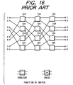
- Fig. 16 shows a second structural example of the exchange unit 91, which is intended to overcome the problems in the first example of the exchange unit 91.
- This second type of the exchange unit 91 is constructed in a manner that 2 x 2 switches having two inputs and two outputs are connected in a multi-stage form.
- each of switches 104 is a 2 x 2 switch having two inputs and two outputs and performs both of functions; straight and cross. In the straight function, inputs are connected straight to outputs, while in the cross function inputs are connected crosswise to outputs.
- a set of 2 x 2 switches containing 12 pieces and connected to form a shuffle network constitutes an omega-type exchange unit having eight inputs and eight outputs.
- Fig. 17 shows the internal structure of the 2 x 2 switch 104 having two inputs and two outputs as mentioned above.
- a decoder I 105 and a decoder II 106 each read the address portion of an input packet and instruct the control unit on a corresponding output terminal to which the packet should be output.
- a FIFO (First In First Out) I 107 and a FIFO II 108 temporarily store the input packets and output them to selectors, in order of input, under the control of a control unit 111.
- the selector I 109 and the selector II 110 each select either of the FIFOs 107 and 108, which stores the packet signal to be output to the output destination, under the control of the control unit 111.
- the switch When the selector I 109 selects the FIFO I 107 and the selector II 110 selects the FIFO II 108, the switch is functionally in the straight state. Conversely, if the selector I 109 selects the FIFO II 108 and the selector II 110 selects the FIFO I 107, the switch is in the cross state.
- the required number of the 2 x 2 switches 104 is NlogN-N/2 (the base of the log is 2), so that it can be smaller than that of the first example which includes the N x N switches. Nonetheless, there also arises another problem that the whole of the hardware becomes large because the 2 x 2 switches each require decoders, FIFOs, a control unit and selectors.
- the second example of the exchange unit 91 has the disadvantage that a so-called blocking phenomenon is likely to occur.
- the blocking phenomenon connection with a desired output destination can not be made, depending upon connection conditions of the other inputs, even if the connection has not been made from different inputs to a common output destination.
- the first type of the conventional network system has the disadvantage that the node device increases in cost because of a large-scale hardware of the exchange unit which forms a main component of the node device.
- the second type of the network system is typically constructed as shown in Fig. 19, with the following problems contained therein.
- Fig. 19 shows an example of the second type of the conventional network system, which is constructed in a form in which a plurality of terminal equipments are connected through a bus-type network to a server which performs the usable wavelength assignment for each terminal equipment.
- a bus-type wavelength multiplexed transmission line 114 is an optical fiber cable.
- a server 115 has a wavelength assignment function.
- Blocks 116 each indicate a terminal equipment.
- a power multiplexer and divider 117 guides an optical signal from a variable wavelength transmission unit 118 to the optical fiber 114 and branches an optical signal transmitted on the optical fiber 114 to supply the branched one to a fixed wavelength reception unit 119.
- the variable wavelength transmission unit 118 contains a tunable laser diode (TLD) therein and is operative to convert a packet signal from a packet processing unit 120 into an optical signal having a predetermined wavelength under the control of a wavelength control unit 121 and supply it to the power multiplexer and divider 117.
- the fixed wavelength reception unit 119 is comprised of a filter, through which only an optical signal having a predetermined wavelength can be transmitted by cutting off signals at the other wavelengths, and a photodiode which is operative to convert the optical signal at the predetermined wavelength transmitted through the filter into an electric signal and output the electric signal therefrom.
- the wavelengths to be transmitted through the filters of the fixed wavelength reception units 119 are assigned to the respective terminal equipments such that those assigned wavelengths are different among the terminal equipments.
- the wavelength control unit 121 controls the transmission wavelength from the variable wavelength transmission unit 118 to a desired wavelength.
- an assignment control unit 122 assigns a plurality of usable wavelengths to the respective terminal equipments in the network system and performs the arbitration control such that the wavelength conflict does not occur.
- the conventional network system necessarily has the arbitration function, by which the overlap of wavelengths in use of the respective variable wavelength transmission units 118 in the plural terminal equipments can be prevented, because the optical fiber 114, which is the bus-type wavelength multiplexed transmission line, is commonly used by the respective terminal equipments 116.
- a demand assign method is used to perform the arbitration control.
- the transmitting terminal equipment 116 when transmitting a packet, the transmitting terminal equipment 116 first sets the transmission wavelength of its variable wavelength transmission unit 118 to an fixed wavelength acceptable to the server and sends the server a transmission request packet which clearly designates an address of a destination terminal.
- the server 115 On reception of the transmission request packet, the server 115 looks into whether an acceptable wavelength to the destination terminal equipment is available or not. The server then sets the transmission wavelength of its variable wavelength transmission unit 118 to an acceptable wavelength to the transmitting terminal equipment, which has sent the transmission request packet, and sends the transmitting terminal equipment a communication permission packet if available, or a communication non-permission packet if unavailable.
- the transmitting terminal equipment After the terminal equipment, from which the transmission request packet has been sent, receives either of the communication permission/non-permission packets, the transmitting terminal equipment sets the transmission wavelength of its variable wavelength transmission unit 118 to the acceptable wavelength to the addressed terminal equipment and transmits a desired packet, if the communication is found permissive. If not permissive, the transmitting terminal equipment waits for a predetermined interval of time, and re-sends the server the transmission request packet. This operation is repeated until the communication is permitted.
- the arbitration function is thus performed such that the overlap of transmission wavelengths from the respective variable wavelength transmission units of the plurality of terminal equipments can be prevented.
- the filters in the respective terminal equipments are set to transmit therethrough only optical signals having different wavelengths, respectively, so that the wavelength of the optical signal incident on each photodiode can be specific as well. Accordingly, the transmission wavelength is changed at the tunable laser diode (TLD) of the transmitting terminal equipment, thereby realizing the routing function for sending a packet to a desired destination terminal equipment.
- TLD tunable laser diode
- the arbitration control needs to be performed in the server, for all the wavelengths to be used on the network, and this puts too much load on the arbitration control unit of the server, so that arbitration itself takes much time, resulting in lowering of throughput in the network system.
- the wavelength control unit of each terminal equipment needs to adjust the transmission wavelength to a predetermined wavelength each time communication is conducted with the server and with the addressed receiving terminal equipment. This requires high-speed wavelength control, resulting in a large-scale hardware.
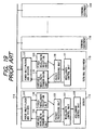
- a control unit 123 of the node device includes a buffer control unit for controlling the read-out of buffers and a wavelength control unit for controlling the transmission wavelengths of variable wavelength transmission units.
- An optical fiber 124 is used as an optical wavelength multiplexed transmission line.
- a power divider 125 divides an optical signal transmitted on the optical fiber 124 into eight portions and output them to eight fixed wavelength reception units.
- the fixed wavelength reception units I 126 to VIII 133 are photodiodes and serve as fixed wavelength reception means.
- the fixed wavelength reception units I 126 to VIII 133 each receive only a packet which is transmitted as one of optical signals having wavelengths ⁇ 1 to ⁇ 8.
- Separation-insertion units I 134 to VIII 141 serve as separation-insertion means, each of which is operative to separate a packet, which is to be transmitted to a sub-transmission line, out of a packet stream from each of the fixed wavelength reception units 126 to 133 and transmit it to the sub-transmission line, while it is operative to add a packet from the sub-transmission line to the packet stream from the fixed wavelength reception unit.
- Buffers I 142 to VIII 149 serve as buffer means to temporarily store the packets from the separation-insertion units.
- Variable wavelength transmission units I 150 to VIII 157 are variable wavelength transmission means, which convert, under the control of the wavelength control unit, the packets from the buffers 142 to 149 into optical signals each having a predetermined wavelength out of wavelengths ⁇ 1 to ⁇ 8 and send them through a wavelength multiplexer 158 to the optical fiber 124.
- the wavelength multiplexer 158 multiplexes the optical signals of wavelengths ⁇ 1 to ⁇ 8 which are sent from the eight variable wavelength transmission units 150 to 157, and supplies them to the optical fiber 124.
- Sub-transmission lines I 159 to VIII 166 serve as packet transmission lines between the separation-insertion units 134 to 141 and terminal equipments I 167 to VIII 174.
- the terminal equipments I 167 to VIII 174 are connected to the sub-transmission lines I 159 to VIII 165, respectively.
- Each of the terminal equipments receives a packet output from each of the corresponding separation-insertion units 134 to 141, while it generates a packet to be transmitted to another terminal equipment and sends it through each of the sub-transmission lines 159 to 166 to each of the separation-insertion units 134 to 141.
- Fig. 21 is a block diagram of a network system in which four node devices of Figs. 20A and 20B are connected by optical fibers. Node devices 175 to 178 shown in Figs. 20A and 20B are respectively connected to eight terminal equipments 167 to 174 through eight sub-transmission lines 159 to 166. Optical fibers 179 to 182 are each used as an optical wavelength multiplexed transmission line.
- a packet from the terminal equipment is inserted, in each of the separation-insertion units 134 to 141, into the packet stream from each of the fixed wavelength reception units 126 to 133.
- the packet is temporarily stored in each of the buffer units 142 to 149, and then sent out from each of the variable wavelength transmission units 150 to 157 as an optical signal at a predetermined wavelength.
- the packet is relayed in the node devices located on the way to a node device which is connected to an addressed destination terminal equipment.
- the packet is then converted into an optical signal at a wavelength, which can be received by one of the fixed wavelength reception units 126 to 133 for outputting the packet to one of the separation-insertion units 134 to 141 connected to the addressed sub-transmission line, and transmitted from one of the variable wavelength transmission units 150 to 157 in the node device upstream of the node device connected to the addressed destination terminal equipment.
- the packet is finally received by the fixed wavelength reception unit in this node device, then output from the separation-insertion unit therein to the sub-transmission line and received by the addressed terminal equipment.
- the exchange unit required in the above-discussed first type of the network system is made unnecessary, and thus an increase in the hardware scale of the node device can be prevented and a relatively low-cost node device is obtained.
- the arbitration control which adversely affects the improvement of throughput of the network system, can be dispensed with, and the routing control is simplified.
- the transmitting terminal equipment and the addressed terminal equipment are respectively connected to different separation-insertion units in the same node device (also referred to as this node device, own node device, transmitting node device, source node device or the like in the specification)
- a packet is transmitted via a somewhat winding route as follows.
- the packet is transmitted from the variable wavelength transmission unit, and relayed in all of the node devices located in a ring form other than the transmitting node device. Then, the packet is received by the fixed wavelength reception unit for outputting the packet to the separation-insertion unit connected to the addressed terminal equipment. The packet is output from the separation-insertion unit to the sub-transmission line, and finally received by the addressed terminal equipment. Thus, in such a case, a packet is relayed in all the node devices but the transmitting node device.
- EP-A-0 758 173 discloses a node device used in a network system for performing a packet communication.
- the node device has a packet processing means, a buffer for temporarily storing a packet, and a selection means for selecting a channel to which the buffer is to be connected.
- the selection means can select a channel from a channel connected to another node device and a channel connected to the packet processing means.
- a packet addressed to the packet processing means is read out from the buffer when the buffer is connected to the channel connected to the packet processing means side via the selection means.
- EP-A-0 621 700 relates to a network system which includes a wavelength-multiplexing transmission path for multiplexing and transmitting a plurality of wavelengths, and a plurality of terminal equipments connected to the transmission path.
- a transmission wavelength and a reception wavelength are assigned in advance to each of the plurality of terminal equipments.
- the present invention has been made in view of the above-discussed problems, and an object thereof is to provide a novel structure for a node device preferably allowing to perform a transmission through two sub-transmission lines connected to a common node device, or between terminal equipments connected to different sub-transmission lines belonging to a common node device.
- the node device may be part of a network system containing a plurality of node devices connected therebetween.
- node device as defined in claim 1 or any one of the dependent claims.
- a plurality of such node devices may be connected with each other to transmit a signal therebetween and a sub-transmission line is connected to the node device.
- a part of plural channels from the connection means may be connected to the separation unit and a signal can be output to the sub-transmission line and the terminal equipment connected to this sub-transmission line through the separation unit, so that communication between the terminal equipments connected to the same node device can be performed with no other node devices being used.
- a signal from the sub-transmission line is input into the connection means through the insertion unit and the buffer.
- the number of inputs into the connection means can be reduced in this network system.
- a signal from another node device can also be input into the separation unit, so that the signal from another node device can be output to the sub-transmission line through the separation unit.
- the structure To transmit the signal from the signal transmitting node device to another node device, the structure only needs to be constructed such that a channel other than the part of the plurality of channels is connected to another node device.
- the above structure may be preferably constructed such that numbers of the separation units and the part of the plurality of channels are respectively plural and equal to each other and that different channels of the part of the plurality of channels are respectively connected to the separation units.
- the structure is constructed such that the signal from another node device is input into the separation unit, that numbers of the separation units and the buffers are respectively plural and equal to each other, that the separation units are respectively connected to the buffers, and that a signal, which is not to be output from the separation unit to the sub-transmission line, is input into the buffer to which the separation unit is connected.
- the insertion unit is disposed between the separation unit and the buffer. This is because, when the signal is separated in the separation unit and guided to the sub-transmission line, there occurs an empty portion in the signal stream and a signal from the sub-transmission line can be readily inserted into the signal stream in the insertion unit.
- the structure may be constructed such that the connection means sequentially alters the channels, to which the buffers respectively output signals, in a predetermined sequence and that a signal of signals stored in the buffer, which is to be output to a predetermined channel, is output from the buffer when the buffer is connected to the predetermined channel.
- the arbitration can be dispensed with. In the arbitration, the address of each signal is detached, and the respective buffers are controlled each time the signal is to be transmitted, such that the buffers do not use the same channel contemporaneously.
- the plurality of channels are channels which are respectively discriminated from each other by optical wavelengths, or the plurality of channels are respectively different transmission lines.
- connection means may include a plurality of variable channel transmission means which are provided corresponding to the plurality of buffers, respectively, and a channel, to which the buffer is connected, may be selected by altering an output channel of the variable channel transmission means. More specifically, wavelength tunable light sources may be used.
- the connection means may be constructed without using any switching means.
- the node device may include means for taking out the part of the plurality of channels from outputs of the plurality of variable channel transmission means and outputting the taken-out channel to the separation unit.
- this means is preferably the combination of a power divider and means for selectively transmitting or reflecting the wavelength (for example, a wavelength band pass filter), or a demultiplexer whose output ports branch off depending on the wavelengths.
- the part of the plurality of channels can be effectively picked out by constructing the node device such that it includes means for inputting the outputs of the plurality of variable channel transmission means and a signal input from another node device, into a common transmission line (for example, a multiplexer), and means for taking out the part of the plurality of channels from the common transmission line and outputting the taken-out channel to the separation unit (for example, the combination of a divider and a wavelength filter).
- a common transmission line for example, a multiplexer
- the separation unit for example, the combination of a divider and a wavelength filter
- connection means may be comprised of connection alteration means for connecting inputs from the plurality of buffers to the plurality of channels.
- connection alteration means for connecting inputs from the plurality of buffers to the plurality of channels.
- inter-node and intra-node communications can be respectively performed without increasing the number of channels in use, when the structure is built such that a channel other than the part of the plurality of channels is to be output to another node device, that the part of the plurality of channels in a first node device is common to a channel other than the part of the plurality of channels in a second node device which is a node device for inputting the signal into the first node device, and that a channel other than the part of the plurality of channels in the first node device is common to the part of the plurality of channels in a third node device which is a node device to which the first node device outputs the signal.
- signals from an other node device and this source node device do not collide with each other, when the connection means in the mutually-adjacent node devices are synchronously controlled and a common channel is not selected contemporaneously.
- connection means sequentially alters the channels, to which the plurality of buffers output signals, respectively, in a predetermined sequence, and that the predetermined sequence includes a first transmission period, during which the connection means connects the respective buffers to the part of the plurality of channels, and a second transmission period during which the connection means connects the respective buffers to a channel other than the part of the plurality of channels. More specifically, when the predetermined sequence is weighted such that one of the first and second transmission periods is longer than the other period, it is possible to preferably cause the channels, which have larger amount of signals to be transmitted, to effectively a lot of transmit a lot of signals therethrough.
- the signal to be transmitted in the present invention is preferably a packet with address information.
- the packet may have a fixed length or a variable length, and may include a cell which is so called in ATM communication.
- a plurality of such node devices may be connected with each other to transmit a signal therebetween, and a sub-transmission line may be connected to the node device, the node device including a plurality of buffers for temporarily storing a signal to be transmitted, connection means for selecting a channel, to which the signal from each buffer is to be output, from a plurality of channels in such a manner that the plurality of buffers are contemporaneously connected to the different channels, respectively, a separation unit for receiving the signal to be transmitted along a part of the plurality of channels and outputting the signal to the sub-transmission line to which this node device is connected, and an insertion unit for inputting a signal from the sub-transmission line, to which this node device is connected, into the buffer.
- a signal, which is to be output to the sub-transmission line of this node device, out of the signals stored in the buffer is output from the buffer, when the buffer is connected to the part of the plurality of channels receivable by the separation unit to which the sub-transmission line is connected.
- communication with another node device is possible, when the node device outputs a channel other than the part of the plurality of channels to another node device, and the buffer is so constructed as to output a signal, which is to be output to another node device, out of the signals stored in the buffer, when the buffer is connected to the channel other than the part of the plurality of channels.
- the signal directed to the sub-transmission line is transmitted through the separation unit, so that the construction may be built such that when the signal to be output to another node device is a signal to be output to the sub-transmission line of another node device adjacent to this node device on the downstream side in the transmission direction, the buffer outputs the signal when the buffer is connected to a channel receivable by the separation unit in the adjacent node device, to which the addressed sub-transmission line is connected.
- connection means can select the channel, to which the buffer outputs the signal, and that the separation unit can decide whether or not the signal is to be output to the sub-transmission line. Therefore, the connection means only needs to decide which channel is to be used to transmit the signal.
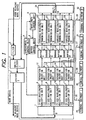
- Fig. 1 is a view of a node device illustrating a first embodiment according to the present invention, in which four sub-transmission lines are connected with a ring-type optical wavelength multiplexed transmission line containing eight channels of wavelengths ⁇ 1 to ⁇ 8. Each of the sub-transmission lines is coupled to a terminal equipment.
- a power divider I 1 is a dividing means for dividing optical signals of plural wavelengths output from a multiplexing means into portions to be guided to the wavelength multiplexed transmission line and plural fixed wavelength reception means in the node device including this power divider I 1.
- the wavelength multiplexed optical signals from a multiplexer I 2 are divided and output to the divider II 7 and to an adjacent node device through the wavelength multiplexed transmission line composed of an optical fiber (not shown).
- the multiplexer I 2 is the multiplexing means for combining the optical signal transmitted through an optical demultiplexing means with optical signals output from plural variable wavelength transmission means in the node device including this multiplexer I 2.
- the combined optical signals from a filter 3 and a multiplexer II 24 are output to the divider II.
- the filter 3 is the optical demultiplexing means for transmitting only a desired optical signal therethrough out of the signals of plural wavelengths transmitted on the ring-type wavelength multiplexed transmission line.
- the filter 3 intercepts optical signals, which can not be received by the plural fixed wavelength reception means in this node device, out of the optical signals output from the adjacent node device via the wavelength multiplexed transmission line composed of an optical fiber (not shown).
- a synchronous control unit 4 separates a synchronizing signal from an optical signal received by a fixed wavelength reception unit I 8 to conduct a synchronization among the node devices connected in the network system of this embodiment, and outputs the synchronization signal to a wavelength control unit 6.
- a buffer control unit 5 controls buffers so that, when an addressed sub-transmission line memorized in a buffer is connected to the adjacent node device on a downstream side in the transmission direction, or to this node device, the packet can not be read out from the buffer until two wavelengths match up to each other; one is a wavelength receivable by a fixed wavelength reception unit from which the packet is output to a separation-insertion unit to which the addressed receiving terminal equipment is connected via the adjacent node device or this node device, and the other is a transmission wavelength of a variable wavelength transmission unit from which the packet in the buffer is transmitted. This is because the packet must be output at a wavelength or a channel, to which the addressed sub-transmission line is connected, in this node device.
- the wavelength control unit 6 controls transmission wavelengths of the variable wavelength transmission units in accordance with a predetermined transmission-wavelength control pattern described later, on the basis of the synchronizing signal output from the synchronous control unit 4.
- the divider II 7 divides optical signals output from the divider I 1 into four portions to output them to the four fixed wavelength reception units.
- the fixed wavelength reception units I 8 to IV 11 are photodiodes and serve as fixed wavelength reception means.
- the eight optical wavelengths are classified into a first wavelength group of wavelengths ⁇ 1 to ⁇ 4 and a second wavelength group of wavelengths ⁇ 5 to ⁇ 8 Corresponding to those optical wavelengths, the wavelengths of ⁇ r1 to ⁇ r4 are respectively ⁇ 5 to ⁇ 8 in a first group of node devices, while the wavelengths of ⁇ r1 to ⁇ r4 are respectively ⁇ 1 to ⁇ 4 in a second group of node devices.
- wavelengths ⁇ s1 to ⁇ s4 are respectively wavelengths ⁇ 1 to ⁇ 4, while in the second group of the node devices, the wavelengths ⁇ s1 to ⁇ s4 are respectively wavelengths ⁇ 5 to ⁇ 8.
- Separation-insertion units I 12 to IV 15 serve as separation-insertion means, each of which is operative to separate a packet, which is to be transmitted to the sub-transmission line, out of a packet stream from the fixed wavelength reception units I to IV and transmit it to the sub-transmission line, while it is operative to add a packet from the sub-transmission line to the packet stream from the fixed wavelength reception units I to IV.
- the internal structure of the separation-insertion unit will be also described later.
- Buffers I 16 to IV 19 serve as buffer means for temporarily storing the packets from the separation-insertion means, the internal structure of which will be also described later.
- Variable wavelength transmission units I 20 to IV 23 are tunable laser diodes (TLDs) and serve as variable wavelength transmission means, which convert, under the control of the wavelength control unit, the packets from the buffers I to IV into optical signals each having a predetermined wavelength out of wavelengths ⁇ 1 to ⁇ 8 and send them to the multiplexer II 24, the internal structure of which will be also described later.
- TLDs tunable laser diodes
- the wavelength multiplexer II 24 multiplexes the optical signals of wavelengths ⁇ 1 to ⁇ 8 which are sent from the four variable wavelength transmission units I to IV and applies them to the multiplexer I 2.
- Sub-transmission lines I 25 to IV 28 serve as packet transmission lines between the separation-insertion units and the terminal equipments.
- Terminal equipments I 29 to IV 32 are connected to the sub-transmission lines I to IV, respectively.
- Each of the terminal equipments receives a packet output from the corresponding separation-insertion units I to IV, while it generates a packet to be transmitted to another terminal equipment and sends it to the separation-insertion units I to IV through the sub-transmission lines I to IV.
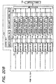
- Fig. 2 is a block diagram of a network system illustrating the first embodiment according to the present invention, in which four node devices of Fig. 1 are connected by optical fibers.
- Node devices 33 to 36 shown in Fig. 1 are respectively connected through the four sub-transmission lines with four terminal equipments.
- Optical fibers 37 to 40 are each used as an optical wavelength multiplexed transmission line.
- the transmission direction of the optical signals is a counter-clockwise direction.
- the node devices I 33 and III 35 belong to the first group and the node devices II 34 and IV 36 belong to the second group.
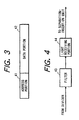
- Fig. 3 illustrates the structure of a packet to be transmitted in this embodiment.
- Numeral 41 designates an address portion of the addressed terminal equipment of this packet.
- Numeral 42 is a data portion carried by this packet.
- bit lengths of the address portion 41 and data portion 42 are fixed, but those may be variable. Those only need to be decided as a network setting specification.
- Fig. 4 shows the internal structure of each of the fixed wavelength reception units I 8 to IV 11 which are utilized in the node device of the first embodiment according to the present invention.
- a filter 43 transmits only an optical signal having a fixed wavelength assigned to each fixed wavelength reception unit, while optical signals of the other wavelengths being intercepted.
- each of the filters in each fixed wavelength reception unit transmits a wavelength specifically assigned to each of the fixed wavelength reception units; ⁇ r1 to the fixed wavelength reception unit I 8, ⁇ r2 to the fixed wavelength reception unit II 9, ⁇ r3 to the fixed wavelength reception unit III 10, and ⁇ r4 to the fixed wavelength reception unit IV 11.
- a reception unit 44 is a photodiode for converting the optical signal, transmitted through the filter 43 at the predetermined wavelength, into an electric signal and outputting it to the separation-insertion unit.
- This reception unit contains therein a pin photodiode (Pin-PD), the back stage of which is connected to an amplifier for amplifying a sensed electric signal, an equalizer for compensating for a difference from a predetermined level and a discrimination circuit for waveform-shaping the signal prior to its output operation of the input packet.
- Pin-PD pin photodiode
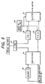
- Fig. 5 shows the internal structure of each of separation-insertion units I 12 to IV 15 which are utilized in the node device of the first embodiment according to the present invention.
- the same internal structure is applied to all the separation-insertion units and the description will be made with respect to only one unit.
- a decoder I 45 reads the address portion of an input packet and instructs a demultiplexer I 46 as to whether the packet should be output to the sub-transmission lines 25 to 28 or not.
- the demultiplexer I 46 outputs the input packet to an I/F unit 47 or a FIFO II 49 in accordance with instructions from the decoder I 45.
- the I/F unit 47 is operative to send the packet from the demultiplexer I 46 to the terminal equipments 29 to 31 through the sub-transmission lines 25 to 28 and output a packet from the sub-transmission lines 25 to 28 to a FIFO I 48.
- the FIFOs (First In First Out) I 48 and II 49 temporarily store the input packets and output them to a selector I 51, in order of input, in accordance with control instructions from an insertion control unit 50.
- the insertion control unit 50 controls reading operation of both the FIFO I 48 and FIFO II 49.
- the insertion control unit 50 also instructs a selector I 51 as to which FIFO of the FIFOs 48 and 49 should be selected, so that the packet transmitted on the sub-transmission lines 25 to 28 can be added to the packet stream from the fixed wavelength reception units 8 to 11.
- the selector I 51 selects the FIFO 48 or 49 in accordance with instructions from the insertion control unit 50, the FIFO storing the packet to be output.
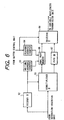
- Fig. 6 shows the internal structure of each of buffers I 16 to IV 19 which are utilized in the node device of the first embodiment according to the present invention.
- the same internal structure is applied to all of the buffers I 16 to IV 19 and the description will be made with respect to only one buffer.
- a decoder II 52 reads the address portion 41 of the input packet and determines whether or not a destination of the packet is the terminal equipment connected to the node device, in which those buffers are contained, or the adjacent node device. If not, the decoder II 52 instructs a demultiplexer II 55 to set its output destination to a FIFO III 57.
- the decoder II 52 instructs the demultiplexer II 55 to set its destination to a dual port memory 56, and at the same time instructs a writing address counter 53 to set a writing start address value of the dual port memory 77, into which the packet to be written, in accordance with a wavelength to be received by the fixed wavelength reception means from which the packet is output to the separation-insertion means 12 to 15 in this node device or the adjacent node device to which the addressed destination sub-transmission line is connected.
- the writing address counter 53 starts with the writing start address value, which is output from the decoder II 52, and outputs address signals for writing the packet from into the dual port memory 56 in due order.
- a reading address counter 54 starts with an offset value as a reading start address, which is output from the buffer control unit 5, and outputs address signals for reading the packet from the dual port memory 56 in due order.
- the demultiplexer II 55 outputs the input packet to the dual port memory 56 or the FIFO III 57 in accordance with instructions from the decoder II 52.
- the dual port memory 56 is operative to perform reading and writing of the packet data independently.
- Memory regions of the dual port memory 56 is divided into eight regions; memory regions I to VIII, in accordance with wavelengths for transmitting packets, each of which corresponds to each channel, i.e., either of transmission wavelengths ⁇ 1 to ⁇ 8.
- a start of address in each memory region is A1, A2, A3, A4, A5, A6, A7 or A8.
- the FIFO (First In First Out) III 57 temporarily stores the packets input thereinto and outputs them to a selector II 58 in order of input, under the control of the reading control unit.
- the selector II 58 selects, in accordance with instructions from the buffer control unit 5, either of outputs; one is from the dual port memory 56 and the other is from the FIFO III 57, and outputs it to the variable wavelength transmission units I to IV.
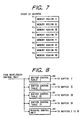
- Fig. 8 shows the internal structure of the buffer control unit 5 which is utilized in the first embodiment according to the present invention.
- buffer control tables I 59 to IV 62 are read out in order in response to the address value which is output from the wavelength control unit 6. Then, predetermined offset values are respectively output to the reading address counters 54 in the buffers I to IV. These tables are incorporated in a read-only memory (ROM). The contents of the buffer control tables I 59 to IV 62 will be described later.
- a reading control unit 63 counts clock signals which are output from the wavelength control unit 6, so that the reading control signal can be output to the buffers I 16 to IV 19.
- the reading control signal controls the read-out of both the dual port memory 56 and the FIFO III 57.
- Fig. 9 shows the internal structure of the wavelength control unit 6 which is utilized in the first embodiment according to the present invention.
- wavelength control tables I 64 to IV 67 are read out in order in response to the address value which is output from a 2-bit ROM counter 68. Then, predetermined wavelength control signals are respectively output to respective drive units in the variable wavelength transmission units 20 to 23. These tables are also incorporated in the read-only memory (ROM). The contents of the wavelength control tables I 64 to IV 67 will be also described later.
- a clock generating unit 69 generates a predetermined clock signal, frequency-demultiplies it and outputs the demultiplied one to the ROM counter 68 and further to the buffer control unit 5 from the ROM counter 68.
- Fig. 10 shows the internal structure of each of variable wavelength transmission units I 20 to IV 23 which are utilized in the node device of the first embodiment according to the present invention.
- the same internal structure is applied to all of the variable wavelength transmission units I 20 to IV 23 and the description will be made with respect to only one unit.
- a drive unit 70 includes a signal superimposing unit 72 and a current injection unit 71 therein.
- the current injection unit 71 controls bias current values which are to be respectively injected into three regions of a DBR-type tunable laser diode (TLD); emission active region, phase control region and DBR region, in response to the wavelength control signal output from the wavelength control unit 6, so as to control the transmission wavelengths to predetermined ones.
- the signal superimposing unit 72 superimposes an electric signal from the buffers 16 to 19 on the bias current from the current injection unit 71, so that the optical signal, to which intensity modulation has been made at a predetermined wavelength, can be sent from the DBR-type tunable laser diode (TLD) 73.
- TLD DBR-type tunable laser diode
- the DBR region 74 varies its refractive index in accordance with an amount of injected carriers so that the transmission wavelength can be varied.
- the phase control region 75 matches phases of the transmission wavelength in the DBR region 74 and the emission active region 76 to each other.
- the emission active region 76 is an active region for laser oscillation.
- represented by numeral 77 is a diffraction grating which makes a single-mode transmission wavelength in the DBR region 74.
- the contents of the wavelength control tables I 64 to IV 67 mentioned above are set as shown in Table 1 below.
- the table 1 shows the wavelengths transmitted from the variable wavelength transmission units 20 to 23 under the control of the wavelength control unit 6. Further, the offset values of the buffer control tables I 59 to IV 62 are set as shown in Table 2.
- Those eight tables are all read out synchronously by the ROM counter 68. Circular transition phases of the transmission wavelengths of the respective tunable laser diodes (TLDs) are shifted from each other such that those TLDs do not transmit signals at the same wavelength. As discussed above, the transmission wavelength control pattern is determined in accordance with the wavelength control tables I to IV.
- the memory regions I to VIII in the dual port memory 56 in the buffers I to IV shown in Fig. 6 respectively correspond to the wavelengths to be received by the fixed wavelength reception units 8 to 11 from which the packet is output to the separation-insertion units 12 to 15 connected to the addressed sub-transmission lines 25 to 28 in the adjacent node device or their own node device.
- the packet data stored in each buffer I to IV is not read out from the buffer under control until the wavelength of the variable wavelength transmission unit I to IV matches up to the wavelength receivable by the fixed wavelength reception unit I to IV from which the packet is output to the separation-insertion unit I to IV connected to the addressed sub-transmission line 25 to 28 in the adjacent node device or their own node device.
- the packet to be transmitted is called a packet A.
- the same elements in different node devices are represented by common reference numerals used in Figs. 1 through 10 for convenience' sake.
- the operation of the node device is composed of eight consecutive operation periods T1, T2, T3, T4, T5, T6, T7 and T8.
- the eight operation periods are each divided into a period Td for reading the dual port memory 56 and a period Tf for reading the FIFO III 57 in accordance with the buffer operation.
- Td the dual port memory 56, in which the packet to be output at a predetermined channel or wavelength is stored, is read.
- the FIFO III 57 in which the packet allowed to be output at any predetermined channel or wavelength, is read.
- operation periods T1 to T4 constitute a first transmission period (Ts) in which the packet is transmitted at a wavelength different from the wavelengths receivable by the plural fixed wavelength reception units I to IV contained in this packet-transmitting node device, and which is a period during which the packet is relayed between the node devices.
- operation periods T5 to T8 constitute a second transmission period (Tr) in which the packet is transmitted at a wavelength equal to one of the wavelengths receivable by the plural fixed wavelength reception units I to IV contained in this packet-transmitting node device, and which is a period during which the packet is relayed in this node device.
- the transmitting terminal equipment I 29 connected to the node device I 33 through the sub-transmission line I 25 composes the packet A of both the data portion to be transmitted to the receiving terminal equipment IV 32 connected to the node device IV 35 through the sub-transmission line IV 28, and the address portion to exhibit the address of the receiving terminal equipment IV 32 connected to the node device IV 35 through the sub-transmission line IV 28, as shown in Fig. 3.
- the transmitting terminal equipment I 29 then transmits the packet A through the sub-transmission line I 25 to the separation-insertion unit I 12 in the node device I 33.
- the I/F unit 47 in the separation-insertion unit I 12 of the node device I 33 receives the packet A from the sub-transmission line I 25 and writes it in the FIFO I in due order.
- the insertion control unit 50 finds a break in the packet stream read out from the FIFO II 49, causes the selector I 51 to change its output from the input of FIFO II 49 to the input of FIFO I 48, stops reading from the FIFO II 49 and starts reading from the FIFO I 48, so that the packet from the FIFO I 48 can be output from the selector I 51.
- the insertion control unit 50 After completion of reading the packet A from the FIFO I 48, the insertion control unit 50 stops reading from the FIFO I 48 and starts again reading from the FIFO II 49, so that the packet from the FIFO II 49 can be output again from the selector I 51. The packet A from the selector I is then input into the buffer I 16.
- the decoder II 55 reads the address portion of the input packet A.
- the node device I treats the packet A as being a packet to which the predetermined transmitting wavelength (channel) need not be assigned, and the decoder II 52 sets such that the demultiplexer II 55 outputs to the FIFO III 57.
- the packet A is written in the FIFO III during the operation period T8, it is to be read out, under the control of the buffer control unit 5, during the reading period Tf for the FIFO III 57 in the subsequent operation period T1.
- the ROM counter 68 in the wavelength control unit 6 outputs "0" as a reading address value to the wavelength control tables I 64 through IV 67 at the same time, so that the contents of the wavelength control tables are read out in accordance with the address value.
- These control signals are input to the drive units 70 in the variable wavelength transmission unit I 20 through the variable wavelength transmission unit IV 23, respectively.
- a current to be injected by the current injection unit 71 is determined in accordance with the above wavelength control signal such that the transmission wavelength in each tunable laser diode (TLD) can be set to a predetermined wavelength.
- the reading address value "0" from the ROM counter 68 in the wavelength control unit 6 is input into the buffer control tables I 59 through IV 63 in the buffer control unit 5. The contents of these buffer control tables I to IV are then read out in accordance with this address value.
- the content to be read out from the buffer control table I 59 is, as shown in Table 2, the offset value A1 corresponding to the memory region I.
- contents to be read out from the other buffer control tables II 60, III 61 and IV 62 are the offset values A4, A3 and A2 respectively corresponding to the memory regions IV, III and II.
- These offset values are output to the reading address counters 54 in the buffer I 16 through the buffer IV 19, respectively.
- the reading control unit 63 in the buffer control unit 5 outputs control signals, in response to the clock signal from the wavelength control unit 6, such as a signal for permitting reading of the dual port memory 56, a signal for inhibiting reading of the FIFO III 57 and a signal for setting the input from the dual port memory 56 to be output from the selector II 58.
- control signals in response to these control signals, the reading address counter 54 in the buffer I 16 starts loading thereinto the offset value A1 from the buffer control table I 59, and counts up by an increment in due order. The counter 54 thus generates an address for reading the packet written in the memory region I and outputs it to the dual port memory 56.
- the reading address causes the dual port memory 56 to read out and output the packet from the output port thereof to the variable wavelength transmission unit I 20 in due order. It will be understood that the packet to be read out at the moment is destined for the terminal equipment I 29 connected to the adjacent node device II 34 through the sub-transmission line I 25 because its transmission wavelength is ⁇ 1.
- the offset value A4 is simultaneously loaded from the buffer control table II 60 into the reading address counter 54 in the buffer II 17, so that the packet written in the memory region IV is read out from the dual port memory 56 and output to the variable wavelength transmission unit II 21 in the same manner as that of the buffer I 16.
- the packets are read out from the memory regions III and II in the buffers III 18 and IV 19 and output to the variable wavelength transmission units III 22 and the variable wavelength transmission unit IV 34, respectively.
- the packets to be read out during the reading period Td are destined for the terminals equipments connected to the adjacent node device II 34 through the sub-transmission lines I 25 to IV 28, respectively.
- the reading control unit in the buffer control unit 5 outputs control signals, in response to the clock signal from the wavelength control unit 6, such as a signal for inhibiting reading of the dual port memory 56, a signal for permitting reading of the FIFO III 57 and a signal for setting the output of the FIFO III 57 to be output from the selector II 58.
- control signals in response to the clock signal from the wavelength control unit 6, such as a signal for inhibiting reading of the dual port memory 56, a signal for permitting reading of the FIFO III 57 and a signal for setting the output of the FIFO III 57 to be output from the selector II 58.
- the packet in the FIFO III 57 is read out and output to the variable wavelength transmission unit I 20 through the selector II 58 in the buffer I 16.
- the packet in the FIFO III 57 is read out in due order and output to the variable wavelength transmission unit II 21 through the variable wavelength transmission unit IV 23, respectively.
- the packet A is transmitted as the optical signal at the wavelength ⁇ 1 from the variable wavelength transmission unit I 20.
- Optical signals, transmitted from the node device IV 36 adjacent to the node device I on the upstream side and transmitted through the filter 3, are also input into the multiplexer I 2.
- optical signals are input into the filter 3 via the optical fiber (not shown). Since the node device I 33 belongs to the first node device group, the filter 3 intercepts the optical signals at the wavelengths ⁇ 1 to ⁇ 4. Therefore, the optical signals at ⁇ 5, ⁇ 6, ⁇ 7 and ⁇ 8 sent out from the node device IV 36 are transmitted through the filter 3 and input into the multiplexer I 2.
- the optical signals at ⁇ 1, ⁇ 2, ⁇ 3 and ⁇ 4 sent out from the variable wavelength transmission units I 20 to IV 23 in the node device I 33 are multiplexed with the optical signals at ⁇ 5, ⁇ 6, ⁇ 7 and ⁇ 8 sent out from the node device IV 36, and the multiplexed signals are output to the divider I 1.
- the optical signals at ⁇ 1 to ⁇ 8 are amplitude-divided and input into the adjacent node device II 34 and the divider II 7. In the divider II 7, those signals are further power-divided into four portions, and input into the fixed wavelength reception units I 12 to IV 15. Since the node device I 33 belongs to the first node device group, the optical signals at ⁇ 5, ⁇ 6, ⁇ 7 and ⁇ 8 are respectively received by the fixed wavelength reception units I 12 to IV 15. Those are signals output from the node device IV 36.
- the optical signals at ⁇ 1 to ⁇ 8 output to the adjacent node device II 34 from the divider I 1 of the node device I 33 are transmitted via the optical fiber 37 and input into the filter 3 of the node device II 34.
- the filter thereof intercepts the optical signals at ⁇ 5, ⁇ 6, ⁇ 7 and ⁇ 8. Therefore, the optical signals at ⁇ 1, ⁇ 2, ⁇ 3 and ⁇ 4 output from the variable wavelength transmission units I to IV of the node device I 33 transmit through the filter 3 and input into the multiplexer I 2.
- the optical signals at ⁇ 5, ⁇ 6, ⁇ 7 and ⁇ 8 output from the variable wavelength transmission units I to IV of the node device IV 36 are intercepted by the filter 3.
- the optical signals at ⁇ 5, ⁇ 6, ⁇ 7 and ⁇ 8 output from the variable wavelength transmission units I to IV of the node device II 34 are multiplexed with the optical signals at ⁇ 1, ⁇ 2, ⁇ 3 and ⁇ 4 output from the variable wavelength transmission units I to IV of the node device I 33 and transmitted through the filter 3, and the multiplexed signals are output to the divider I.
- the optical signals at ⁇ 1 to ⁇ 8 output to the divider I 1 are power-divided by the divider I 1 and output to the divider II 7 and the adjacent node device III 35.
- the signals are further amplitude-divided into four portions and the four portions are respectively input into the fixed wavelength reception units I 12 to IV 15.
- the packet A received by the fixed wavelength reception unit I 8 in the node device II 34 as the optical signal having the wavelength ⁇ 1, is relayed in the node device II 34.
- the packet A received by the fixed wavelength reception unit I 8 in the node device II 34 is output to the separation-insertion unit I 12.
- the decoder I 45 of the separation-insertion unit I 12 the address portion of the input packet A is read. Since the addressed destination of this packet A is the sub-transmission line connected to the adjacent node device III 35 on the downstream side in the transmission direction and this packet A is not a packet to be separated and output to the sub-transmission line connected to this node device, the decoder sets the output of the demultiplexer I 46 to the FIFO II 49.
- the packet A written in the FIFO II 49 is read under the control of the insertion control unit 50, and output to the buffer I 16 through the selector I 51.
- the decoder 52 in the buffer I 16 reads the address portion of the packet A again.
- the packet A is destined for the receiving terminal equipment IV 32 connected to the adjacent node device III 35 through the sub-transmission line IV 28 on the downstream side in the transmission direction, so that the decoder II sets the output destination of the demultiplexer II 55 to the dual port memory 56 and simultaneously outputs the offset value A4 as the writing start address value to the writing address counter 53.
- the writing address counter 53 loads the writing start address therein, counts up by an increment in due order so as to generate the writing address of the input packet A and outputs it to the dual port memory 56.
- the packet A has been already input to the input port of the dual port memory 56 through the demultiplexer II 55, so that the packet A is written in the memory region IV in accordance with the address from the writing address counter 53 in due order.
- the read-out of the packet A from the dual port memory 56 is controlled to stand by until the operation period T4 in which the transmission wavelength of the variable wavelength transmission unit I 20 in the node device II 34 matches up to the wavelength ⁇ 8 receivable by the fixed wavelength reception unit IV for outputting the packet to the separation-insertion unit IV connected to the addressed sub-transmission line IV in the adjacent node device III 35 on the downstream side.
- the packet A thus written in the memory region IV of the buffer I is read out during the reading period Td for the dual port memory in the operation period T4.
- the ROM counter 68 in the wavelength control unit 4 outputs "3" as the reading address value to the wavelength control tables I 64 through IV 67 at the same time. This address value is used to read out the contents of the wavelength control tables.
- the address value "3" is also output to the buffer control unit 5 and the read-out from the buffer control tables is performed.
- the region to be read out from the dual port memory 56 in the buffer I 16 is set to the memory region IV in which the packet A is written.
- the signals in the other buffers are read out under the control of the corresponding control signals, converted into predetermined optical signals in the variable wavelength transmission units and sent through the wavelength multiplexer II 24, the multiplexer I 2 and the divider I 1 to the optical fiber 38, as described above.
- the packet A is read out from the dual port memory during the reading period Td of the operation period T4, sent as the optical signal of ⁇ 8 from the variable wavelength transmission unit I 30 to the optical fiber 38 through the wavelength multiplexer 24 and input into the node device IV 35.
- the optical signals at the wavelengths ⁇ 1 to ⁇ 4 out of the optical signals at the wavelengths ⁇ 1 to ⁇ 8 transmitted from the node device II 34 through the optical fiber 38 are intercepted by the filer 3 in the node device III 35 and then incident on the fixed wavelength reception units I 8 through IV 11 through the multiplexer I 2, divider I 1 and divider II 7.
- the fixed wavelength reception unit IV 11 only the optical signal having the wavelength ⁇ 8 can be transmitted through the filter 43 and is received by the photodiode (PD) 44. Since the packet A is sent from the node device II 34 as the optical signal at the wavelength ⁇ 8, it is received by the fixed wavelength reception unit IV 11. Then, the packet A is output from the fixed wavelength reception unit IV 11 to the separation-insertion unit IV 15.
- the decoder I 45 in the separation-insertion unit IV 15 reads out the address portion of the input packet A.
- the packet A is destined for the receiving terminal equipment connected to the its own separation-insertion unit IV 15, so that the decoder I 45 sets the output destination of the demultiplexer I 46 to the I/F unit 47.
- the packet A is thus output through the demultiplexer I 46 to the I/F unit 47 and received by the addressed receiving terminal equipment IV 32 through the sub-transmission line IV 28.
- a desired processing is performed by extracting only the data portion after removing the address portion of the packet A therefrom.
- the packet A has been transmitted from the transmitting terminal equipment I 29 connected to the transmitting node device I 33 through the sub-transmission line I 25 to the receiving terminal equipment IV 32 connected to the node device III 35 through the sub-transmission line IV 28.
- the packet A is sent at the predetermined wavelength, from the variable wavelength transmission unit I of the node device I, during the first transmission period Ts, it is converted, in the node device II 34 adjacent to the node device III 35 on the upstream side, into the optical signal having the wavelength ⁇ 8 receivable by the fixed wavelength reception unit IV 10 for outputting the packet to the separation-insertion unit IV to which the addressed sub-transmission line of the node device III 35 is connected, during the first transmission period Ts.
- the packet A is then received by the fixed wavelength reception unit IV 11 in the node device III 35, separated in the separation-insertion unit IV 15 and finally received by the terminal equipment IV after transmitted via the sub-transmission line IV 28.
- the transmitting terminal equipment I 29 is connected to the node device I 33 through the sub-transmission line I 25, and the receiving terminal equipment III 31 is also connected to this node device I 33 through the sub-transmission line III 27.
- the packet A is relayed within this node device.
- the transmitting terminal equipment I 29 connected to the node device I 33 through the sub-transmission line I 25 transmits the packet A to the separation-insertion unit I 12.
- the packet A is inserted into the packet stream output from the fixed wavelength reception unit I 8, and then input into the buffer I 16.
- the decoder II 52 of the buffer I 16 the address portion of the packet A input thereinto is read out. Since the address of the packet A is the sub-transmission line III connected to this node device I, the decoder II 52 sets the output destination of the demultiplexer II 55 to the dual port memory 56 and outputs "A7" to the writing address counter 53 as the writing start address value.
- the writing address counter 53 loads this writing start address therein, counts up by an increment to generate the writing address of the input packet A, and outputs the writing address to the dual port memory 56.
- the packet A has been already input into the input port of the dual port memory 56 through the demultiplexer II 55, and starts to be written into the memory region VII in due order, in accordance with the address output from the writing address counter 53.
- the packet A written in the memory region VII of the buffer I is thus read during the reading period Td for the dual port memory in the operation period T7.
- the reading address value of "6" is output from the ROM counter 68 of the wavelength control unit 6 to the wavelength control tables I to IV.
- the contents of the wavelength control tables I to IV are read in accordance with this address value.
- this address value "6" is also output to the buffer control unit 5, and the contents of the buffer control tables I to IV are read out.
- the region of the dual port memory 56 of the buffer I 16 to be read therefrom is set to the memory region VII in which the packet A is written.
- respective buffer I to IV are read out, the read-out signals are converted into signals at predetermined wavelengths in the variable wavelength transmission units I to IV, and those signals are input into the multiplexer I 2 through the multiplexer II 24.
- the packet A is sent out from the variable wavelength transmission unit I 20 as the optical signal at the wavelength ⁇ 7.
- the optical signals of the wavelengths ⁇ 1, ⁇ 2, ⁇ 3 and ⁇ 4 sent out from the node device IV 36 are intercepted by the filter 3.
- the node device III 35 located downstream of the node device IV 36 belongs to the first node device group, and transmits therefrom the optical signals of the wavelengths ⁇ 5, ⁇ 6, ⁇ 7 and ⁇ 8 during the operation period T7 (the second transmission period Tr). Those optical signals, however, are intercepted by the filter 3 in the node device IV 36.
- the optical signals of the wavelengths ⁇ 5 to ⁇ 8 are further divided into four portions, and the divided portions are respectively input into the fixed wavelength reception units I 8 to IV 11. Since the node device I 33 belongs to the first node device group, the fixed wavelength reception units I 8 to IV 11 respectively receive the optical signals of the wavelengths ⁇ 5 to ⁇ 8. Those optical signals are transmitted from the variable wavelength transmission units I to IV in this transmitting node device I 33.
- the fixed wavelength reception unit III 10 only the optical signal of the wavelength ⁇ 7 is transmitted through the filter 43, and received by the light receiving unit 44 of the photodiode (PD). Since the packet A is the packet which is sent from the node device I 33 as the optical signal of the wavelength ⁇ 7, it is received by the fixed wavelength reception unit III 10. The packet A received by the fixed wavelength reception unit III 10 is output to the separation-insertion unit III 14. In the decoder I 45 of the separation-insertion III 10, the address portion of the input packet A is read. Since the address of the packet A is the sub-transmission line III 27 connected to this separation-insertion unit III 14, the decoder I 45 sets the output destination of the demultiplexer I 46 to the I/F unit 47.
- the packet A is thus output to the I/F unit 47 through the demultiplexer and transmitted through the sub-transmission line III 27. After that, the packet A is received by the addressed receiving terminal equipment III 31. After the address portion of the packet A is removed, only the data portion is extracted and a desired processing is performed.
- the packet A has been transmitted from the transmitting terminal equipment I 29 connected to the transmitting node device I 33 through the sub-transmission line I 25 to the receiving terminal equipment III 31 connected to the same node device I 33 through the sub-transmission line III 27.
- the packet A is relayed within the same node device during the second transmission period Tr, and received by the terminal equipment III 31 connected to this node device I 33 through the sub-transmission line III 27.
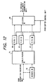
- Fig. 12 shows a modification of the first embodiment in which the internal structure of the buffers I 16 to IV 19 of the first embodiment is modified.
- a decoder III 78 reads the address portion of an input packet, selects a FIFO for writing the packet therein out of FIFOs I 80 to VIII 87 and instructs a demultiplexer III 79 on the selected FIFO.
- the demultiplexer III 79 is operative to output the packet signal input from the separation-insertion units 12 to 15 to the selected FIFO in accordance with the instructions from the decoder III 78.
- the FIFOs I 80 to VIII 87 are provided for respective transmission wavelengths, which temporarily store packet signals from the demultiplexer III 79 and read out them in accordance with the instructions from the buffer control unit 5.
- a selector III 88 selects a predetermined FIFO from the FIFOs I 80 to VIII 87 under the control of the buffer control unit 5, and outputs its output signal to the fixed wavelength transmission unit.
- Table 3 shows an example of the buffer control tables which can be preferably utilized in the buffer structure of Fig. 12. In this example, the numbers of the read-out FIFOs are indicated.
- the structure of the buffer control unit is the same as that of the Fig. 8.
- the FIFOs I to VIII are selected as shown in the buffer control tables of Table 3 during each operation period, so that the written packet signals are read out and output to the variable wavelength transmission units 20 to 23, respectively.
- the FIFO I is selected in the buffer I 16 so that the packet written therein can be read out and output to the variable wavelength transmission unit I 20.
- This embodiment uses a plurality of the FIFOs so that the offset values do not need to be output to the reading address counter 54 described in the first embodiment.
- the structure of the buffer unit can be effectively simplified.
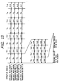
- Fig. 13 illustrates a time chart used in a second embodiment of the present invention.
- the first transmission period Ts during which the transmitting node device transmits signals of wavelengths different from the wavelengths receivable by the plural fixed wavelength reception units contained in this node device, or a period for relaying and transmitting the packet between the node devices is set four times longer than the second transmission period Tr during which the transmitting node device transmits signals of wavelengths equal to the wavelengths receivable by the fixed wavelength reception units contained in this transmitting node device, or a relaying and transmission period within this transmitting node device.
- the operation period Ts is composed of four periods of Ts1, Ts2, Ts3 and Ts4, similarly to the first embodiment.
- One Tr period is provided following this operation period Ts.
- the transmission wavelength of the variable wavelength transmission unit is altered in due order.
- Each of the operation periods Ts and Tr is composed of the dual port memory reading period Td and the FIFO reading period Tf, similarly to the first embodiment.
- the packet transmission is conducted in the same manner as in the first embodiment.
- transmission delay time can be reduced when plural packets are relayed and transmitted between the node devices.
- the number of wavelengths to be received in the transmitting node device itself is four, but this number is not limited to four.
- the number of groups of wavelengths receivable in the transmitting node device itself and wavelengths unable to be received by this node device is set to be two, but this may be more than two.
- the wavelength control pattern is divided into plural groups, and the transmission wavelengths of the variable wavelength transmission units are controlled during the operation periods with timings of such plural groups.
- the filter 3 is located upstream of the multiplexer I 2 to intercept signals at unneeded wavelengths out of signals from the upstream node device, but the filter 3 can be positioned downstream of the power divider I 1. In this case, the filter 3 acts to intercept the wavelengths receivable by the fixed wavelengths reception units of this source node device.
- the combination of optical power divider and wavelength filter is used to select signals at desired wavelengths from the wavelength multiplexed signals, or to intercept signals at unneeded wavelengths.
- a demultiplexer for discriminating signals regarding their output ports on the basis of their wavelengths can be used to perform an equivalent function of the above combination.
- the filter 3 can be removed.
- the filter in the fixed wavelength reception unit is unnecessary.
- a plurality of channels are established by the wavelength division multiplexing in the above-described embodiments, but the multiplexing way is not limited to the optical wavelength multiplexing. In the case of an electrical signal, frequency multiplexing or the like can be employed.
- Figs. 22A and 22B illustrate a structural example of a node device to be used in this case.
- devices common to those in Fig. 1 are denoted by the same numerals.
- Numerals 2202 to 2205 designate reception units I to IV which respectively receive signals transmitted on the separate and independent transmission lines or channels which are to be received by separate reception units. Structures of those reception units can be identical with each other because it is unnecessary for each reception unit to pick out a desired channel from the multiplexed channels.
- Each reception unit is provided with a photodetector for receiving an optical signal.
- a power multiplexer or the like may be disposed if necessary.
- Numerals 2207 to 2214 denote transmission units I to VIII which respectively have laser devices, which can be modulated, for performing optical transmission between transmission units and reception units in this embodiment. In contrast with the first embodiment, wavelengths output by those transmission units are not subjected to alteration for changing the transmission channel.
- the transmission line itself, to which each transmission unit outputs the signal serves as a channel.
- means for altering a channel, to which each buffer outputs a signal is a connection alteration unit 2206.
- connection alteration unit 2206 alters the connection relationship between buffers I 16 to IV 19 and transmission units I 2207 to VIII 2214 under the control of a connection alteration control unit 2201, which corresponds to the wavelength control unit 6 in Fig. 1, in such a manner that the channel, to which each buffer outputs the signal, is altered in a predetermined sequence and that plural buffers do not contemporaneously output signals to a common channel (i.e., they respectively output the signals to different channels, contemporaneously).
- Fig. 23 illustrates the structure of the connection alteration unit. Selectors I 2301 to IV 2304 respectively receive signals from the buffers I to IV, and their output terminals to be selected by those selectors are decided under the control of the connection alteration control unit.
- connection alteration control unit 2201 has the same function as that of the wavelength control unit 6 in Fig. 1, and has connection alteration control tables I to IV indicated in Table 4, in place of the wavelength control tables I to IV of the wavelength control unit 6. Those selectors in the connection alteration unit are controlled in accordance with those control tables I to IV.
- the transmission line, to which the transmission unit I outputs the signal is a channel (referred to as channel I) corresponding to ⁇ s1 in the first embodiment
- the transmission line, to which the transmission unit II outputs the signal is a channel (referred to as channel II) corresponding to ⁇ s2 in the first embodiment
- the transmission line, to which the transmission unit III outputs the signal is a channel (referred to as channel III) corresponding to ⁇ s3 in the first embodiment
- the transmission line, to which the transmission unit IV outputs the signal is a channel (referred to as channel IV) corresponding to ⁇ s4 in the first embodiment
- the transmission line, to which the transmission unit V outputs the signal is a channel (referred to as channel V) corresponding to ⁇ r1 in the first embodiment
- the transmission line, to which the transmission unit V outputs the signal is a channel (referred to as channel V) corresponding to ⁇ r1 in the first embodiment
- the transmission line, to which the transmission line, to which the transmission unit V outputs the signal is a channel (referred
- this source node device is synchronized with another node device by the synchronous control unit 4. That is, timing of alteration of channels, to which the connection alteration unit of another node device inputting signals into this node device outputs signals, is appropriately synchronized with timing of alteration of channels to which the connection alteration unit of this node device outputs signals, so that channels I to IV, into which another node device inputs signals, are not input into the respective reception units I to IV contemporaneously with channels V to VIII into which the transmission units V to VIII of this node device input signals.
- the structures of this node device and a node device adjacent to this node device on the upstream side are made the same as that illustrated in Fig.
- this adjacent node device uses the same connection alteration control tables as this node device uses, and the access to the control tables is performed with the same timing in both of this node device and the adjacent node device.
- two transmission lines are connected to each reception unit, but channels are discriminated from each other, depending on by which reception unit each channel is received, in this embodiment. Therefore, it is important in this embodiment that two transmission lines input into each reception unit are treated as a common channel and that signals are not input from the two transmission lines, which are connected to the same reception unit, contemporaneously.
- channels, to which the buffers are connected are sequentially altered, and the respective buffers output signals, which are to be output to the channels connected to the buffers, when the buffers are respectively connected to the channels.
- signals can be output from the plural buffers without any arbitration control.
- the above-discussed structure can perform an operation fully identical with that of the first embodiment, and devices, such as multiplexers and power dividers, can be dispensed with.
- channels I to IV which are channels directed to another node device, can be multiplexed by some means, so that the configuration of transmission lines between the node devices can be readily established.
- a ribbon fiber is used, or transmission wavelengths of the transmission units I to IV are differentiated from each other to achieve the wavelength multiplexing.
- optical transmission is performed and signals are output to the respective channels through the transmission units, which convert electric signals from output terminals of the connection alteration unit to optical signals
- appropriate transmission drivers can be used instead when transmission is conducted using electric signals.
- outputs from the output terminals of the connection alteration unit can be directly supplied to the separation (insertion) units in this node device and another node device.
- the channel from the connection means is guided to the separation unit in a node device in which this connection means is contained. Therefore, communication between terminal equipments connected to this node device can be performed, without increasing the number of inputs into the connection means, by inputting a signal, which is input from the terminal equipment connected to this node device through the insertion means, into the separation unit of this node device through the connection means.
- channels, to which respective buffers can output signals are sequentially altered in the connection means, and each buffer outputs a signal, which is to be output on a predetermined channel, when this buffer can output the signal to the predetermined channel.
- no arbitration control is needed. Since the sequence of the alteration can be appropriately set, a ratio between time periods, during which each buffer can output to the channel directed to the separation unit of this node device and during which each buffer can output to the channel directed to another node device, can be desirably set. Thus, transmission capacity can be effectively utilized.
- a node device is constructed such that the number of relayings can be reduced where communication is performed between terminal equipments connected to this node device.
- a signal from the terminal equipment is stored in a buffer of the node device.
- a part of output channels of a connection unit for selecting the output channel of the buffer is guided to a separation unit of this node device.
- the separation unit separates a signal, which is to be output to the terminal equipment connected to this separation unit, and sends the separated signal to this terminal equipment.
Landscapes
- Engineering & Computer Science (AREA)
- Computer Networks & Wireless Communication (AREA)
- Signal Processing (AREA)
- Small-Scale Networks (AREA)
- Optical Communication System (AREA)
- Data Exchanges In Wide-Area Networks (AREA)
- Use Of Switch Circuits For Exchanges And Methods Of Control Of Multiplex Exchanges (AREA)
Claims (17)
- Knoteneinrichtung, welche mit einer anderen Knoteneinrichtung durch eine Vielzahl von Kommunikationskanälen verbunden ist, umfassend:eine Vielzahl von Puffern (16-19) zum vorübergehenden Speichern zumindest eines zu übertragenden Pakets;eine Verbindungseinrichtung (20-23, 2206) zum Verbinden der Vielzahl von Puffern mit einem Teil der Vielzahl von Kommunikationskanälen auf eine Art und Weise derart, dass die Vielzahl von Puffern gleichzeitig mit den jeweils verschiedenen Kanälen verbunden sind;eine Vielzahl von Trenneinheiten (12-15), die für jeden Kanal des Teils der Vielzahl von Kommunikationskanälen bereit gestellt sind, zum Ausgeben von über einen entsprechenden Kanal übertragenen Paketen auf eine Unterübertragungsleitung (25-28), die mit der entsprechenden Trenneinheit verbunden ist;eine Vielzahl von Einfügeeinheiten (12-15) zum Eingeben eines Pakets von der Unterübertragungsleitung in den Puffer; undeine Übertragungseinrichtung (20-23, 2206, 2207-2214) zum, auf der Grundlage des Ziels der Pakete, Übertragen der Pakete an einen beliebigen Kommunikationskanal aus dem Teil der Kommunikationskanäle zum Eingeben von Paketen in die Trenneinheiten, oder Übertragen der Pakete an einen anderen Kanal als aus dem Teil der Vielzahl von Kommunikationskanälen.
- Knoteneinrichtung nach Anspruch 1, bei der die Knoteneinrichtung ferner eine synchrone Steuereinheit (4) zum Steuern der Verbindungseinrichtung (20-23, 2206) derart beinhaltet, dass der Puffer (16-19) das entlang des Teils der Vielzahl von Kanälen zu übertragende Paket während einer Zeitspanne, während der das Paket von der anderen Knoteneinrichtung der Trenneinheit zugeführt wird, nicht ausgibt.
- Knoteneinrichtung nach Anspruch 1, bei der ein anderer Kanal als der Teil der Vielzahl von Kanälen an eine andere Knoteneinrichtung ausgegeben wird.
- Knoteneinrichtung nach Anspruch 1, bei der unterschiedliche Kanäle des Teils der Vielzahl von Kanälen jeweils mit der Vielzahl von Trenneinheiten (12-15) verbunden sind.
- Knoteneinrichtung nach Anspruch 1, bei der Nummern der Trenneinheiten (12-15) und der Puffer (16-19) zueinander gleich sind, wobei die Trenneinheiten (12-15) jeweils mit den Puffern (16-19) verbunden sind, und ein Paket, welches von der Trenneinheit nicht auf die Unterübertragungsleitung auszugeben ist, dem Puffer zugeführt wird, mit welchem die Trenneinheit verbunden ist.
- Knoteneinrichtung nach Anspruch 1, bei der die Verbindungseinrichtung (20-23, 2206) sequentiell in einer vorbestimmten Abfolge die Kanäle ändert, auf welche die Vielzahl von Puffern (16-19) jeweils die Pakete ausgeben, und ein in dem Puffer gespeichertes Paket, welches auf einen vorbestimmten Kanal auszugeben ist, von dem Puffer ausgegeben wird, wenn der Puffer mit dem vorbestimmten Kanal verbunden ist.
- Knoteneinrichtung nach Anspruch 1, bei der die Vielzahl von Kanälen Kanäle sind, welche jeweils durch optische Wellenlängen von einander unterschieden werden.
- Knoteneinrichtung nach Anspruch 1, bei der die Vielzahl von Kanälen jeweils unterschiedliche Übertragungsleitungen sind.
- Knoteneinrichtung nach Anspruch 1, bei der die Verbindungseinrichtung (20-23, 2206) eine Vielzahl von variablen Kanalübertragungseinrichtungen beinhaltet, welche jeweils entsprechend der Vielzahl von Puffern (16-19) bereit gestellt sind, und ein Kanal, mit welchem der Puffer zu verbinden ist, durch Ändern eines Ausgangskanals der variablen Kanalübertragungseinrichtung ausgewählt wird.
- Knoteneinrichtung nach Anspruch 9, ferner umfassend eine Einrichtung zum Herausnehmen des Teils der Vielzahl von Kanälen aus Ausgaben der Vielzahl von variablen Kanalübertragungseinrichtungen (12-15) und Ausgeben des herausgenommenen Kanals an die Trenneinheit.
- Knoteneinrichtung nach Anspruch 9, ferner umfassend eine Einrichtung (2) zum Zuführen der Ausgaben der Vielzahl von variablen Kanalübertragungseinrichtungen und eines von einer anderen Knoteneinrichtung zugeführten Pakets zu einer gemeinsamen Übertragungsleitung, und eine Einrichtung (1) zum Herausnehmen des Teils der Vielzahl von Kanälen aus der Übertragungsleitung und Ausgeben des herausgenommenen Kanals an die Trenneinheit (12-15).
- Knoteneinrichtung nach Anspruch 1, ferner umfassend eine Verbindungsänderungseinrichtung (2206) zum jeweils Verbinden von Eingängen von der Vielzahl von Puffern mit der Vielzahl von Kanälen.
- Knoteneinrichtung nach Anspruch 1, bei der ein anderer Kanal als der Teil der Vielzahl von Kanälen an einer andere Knoteneinrichtung (34-36) auszugeben ist, der Teil der Vielzahl von Kanälen in der Knoteneinrichtung für einen anderen Kanal als den Teil der Vielzahl von Kanälen in einer anderen Knoteneinrichtung, welche ein Paket der Knoteneinrichtung zuführt und auf einer vorlagerten Seite zu der Knoteneinrichtung benachbart ist, gemeinsam ist, und ein anderer Kanal als der Teil der Vielzahl von Kanälen in der Knoteneinrichtung zu dem Teil der Vielzahl von Kanälen in einer anderen Knoteneinrichtung, an welche die Knoteneinrichtung ein Paket ausgibt und welche zu der Knoteneinrichtung auf einer nachgelagerten Seite benachbart ist, gemeinsam ist.
- Knoteneinrichtung nach Anspruch 13, bei der die Verbindungseinrichtung (20-23, 2206) in der Knoteneinrichtung und die benachbarten Knoteneinrichtungen synchron gesteuert werden und ein gemeinsamer Kanal nicht gleichzeitig ausgewählt wird.
- Knoteneinrichtung nach Anspruch 1, bei der die Verbindungseinrichtung (20.23, 2206) in einer vorbestimmten Abfolge sequentiell die Kanäle ändert, auf welche die Vielzahl von Puffern (16-19) jeweils Pakete ausgeben, und die vorbestimmte Abfolge eine erste Übertragungsperiode, während welcher die Verbindungseinrichtung (20-23, 2206) die jeweiligen Puffer (16-19) mit dem Teil der Vielzahl von Kanälen verbindet, und eine zweite Übertragungsperiode, während welcher die Verbindungseinrichtung (20-23, 2206) die jeweiligen Puffer mit einem anderen Kanal als dem Teil der Vielzahl von Kanälen verbindet, beinhaltet.
- Knoteneinrichtung nach Anspruch 15, bei der die vorbestimmte Abfolge derart gewichtet wird, dass eine der ersten und der zweiten Übertragungsperiode länger als die andere Periode ist.
- Knoteneinrichtung nach Anspruch 1, bei der das zu übertragende Paket ein Paket mit Adressinformationen ist.
Applications Claiming Priority (6)
| Application Number | Priority Date | Filing Date | Title |
|---|---|---|---|
| JP33323095 | 1995-12-21 | ||
| JP333230/95 | 1995-12-21 | ||
| JP33323095 | 1995-12-21 | ||
| JP33362996 | 1996-12-13 | ||
| JP33362996A JP3639682B2 (ja) | 1995-12-21 | 1996-12-13 | ネットワークシステム及びノード装置 |
| JP333629/96 | 1996-12-13 |
Publications (3)
| Publication Number | Publication Date |
|---|---|
| EP0781006A2 EP0781006A2 (de) | 1997-06-25 |
| EP0781006A3 EP0781006A3 (de) | 2001-07-11 |
| EP0781006B1 true EP0781006B1 (de) | 2004-07-28 |
Family
ID=26574438
Family Applications (1)
| Application Number | Title | Priority Date | Filing Date |
|---|---|---|---|
| EP96120618A Expired - Lifetime EP0781006B1 (de) | 1995-12-21 | 1996-12-20 | Ringnetz mit Wellenlängenmultiplexing |
Country Status (4)
| Country | Link |
|---|---|
| US (1) | US5930014A (de) |
| EP (1) | EP0781006B1 (de) |
| JP (1) | JP3639682B2 (de) |
| DE (1) | DE69632995T2 (de) |
Families Citing this family (23)
| Publication number | Priority date | Publication date | Assignee | Title |
|---|---|---|---|---|
| JPH09289520A (ja) * | 1996-02-19 | 1997-11-04 | Canon Inc | 伝送制御方法及びそれを用いたネットワークシステム |
| JPH1174918A (ja) * | 1997-04-01 | 1999-03-16 | Canon Inc | 通信システム及び通信システムに接続可能な通信装置と、通信システムの制御方法及び通信システムに接続可能な通信装置の制御方法 |
| US7039312B1 (en) | 1997-05-23 | 2006-05-02 | Ciena Corp | Distributed intelligence wavelength division multiplexed network |
| US6163392A (en) * | 1997-05-23 | 2000-12-19 | Ciena Corporation | Distributed intelligence wavelength division multiplexed network |
| US7310688B1 (en) | 1999-08-30 | 2007-12-18 | Ciena Corporation | Relative addressing for network elements |
| AU2001264544A1 (en) * | 2000-02-23 | 2001-09-03 | Tedram Optical Networks, Inc. | Optical communications system |
| WO2001063819A1 (en) * | 2000-02-23 | 2001-08-30 | Tedram Optical Networks, Inc. | Optical network processor for system having channels defined by wavelength, phase, and modulation frequency |
| US6583901B1 (en) * | 2000-02-23 | 2003-06-24 | Henry Hung | Optical communications system with dynamic channel allocation |
| WO2001063805A1 (en) * | 2000-02-23 | 2001-08-30 | Tedram Optical Networks, Inc. | Optical network processor with transceiver for system having channels defined by wavelength, phase, and modulation frequency |
| US6587239B1 (en) * | 2000-02-23 | 2003-07-01 | Henry Hung | Optical fiber network having increased channel capacity |
| WO2001063816A1 (en) * | 2000-02-23 | 2001-08-30 | Tedram Optical Networks, Inc. | Optical communications system having optical signal reference source |
| AU2001260977A1 (en) * | 2000-02-23 | 2001-09-03 | Tedram Optical Networks, Inc. | Optical network processor for system having channels defined by wavelength and modulation frequency |
| WO2001065753A1 (en) * | 2000-02-23 | 2001-09-07 | Tedram Optical Networks, Inc. | Optical network processor with transceiver for system having channels defined by wavelength and modulation frequency |
| GB2361393B (en) * | 2000-04-14 | 2004-01-07 | Ilotron Ltd | Transmission of data |
| US6594045B2 (en) * | 2001-05-23 | 2003-07-15 | Tropic Networks, Inc. | Flexible optical network architecture and optical add/drop multiplexer/demultiplexer therefor |
| CA2357671C (en) * | 2001-05-23 | 2008-05-20 | Wen Liu | Flexible optical network architecture |
| US8271672B1 (en) * | 2001-08-31 | 2012-09-18 | Juniper Networks, Inc. | Guaranteed bandwidth memory apparatus and method |
| JP2003094783A (ja) * | 2001-09-25 | 2003-04-03 | Canon Inc | 画質を診断するシステム、診断方法、診断プログラム、及び診断プログラムが格納された記録媒体 |
| US7698454B1 (en) * | 2001-11-26 | 2010-04-13 | Juniper Networks, Inc. | Interfacing with streams of differing speeds |
| US7747621B2 (en) * | 2003-12-19 | 2010-06-29 | Canon Kabushiki Kaisha | Generating a relation diagram of data files |
| US8014671B1 (en) * | 2006-01-13 | 2011-09-06 | Lockheed Martin Corporation | Wavelength division multiplexed optical channel switching |
| JP4410789B2 (ja) * | 2006-12-08 | 2010-02-03 | 株式会社日立コミュニケーションテクノロジー | パッシブ光ネットワークシステム、光終端装置及び光ネットワークユニット |
| JP2014120050A (ja) * | 2012-12-18 | 2014-06-30 | Renesas Electronics Corp | 半導体装置 |
Family Cites Families (6)
| Publication number | Priority date | Publication date | Assignee | Title |
|---|---|---|---|---|
| JPS58139543A (ja) * | 1982-02-15 | 1983-08-18 | Ricoh Co Ltd | 通信回路網 |
| JPH04334134A (ja) * | 1991-05-10 | 1992-11-20 | Mitsubishi Electric Corp | 通信方式 |
| JPH05153066A (ja) * | 1991-11-25 | 1993-06-18 | Canon Inc | ループ型光lan用ノード及びそれを用いたループ型光lan |
| EP0621700B1 (de) * | 1993-04-23 | 2002-07-17 | Canon Kabushiki Kaisha | Netzwerk mit Wellenlängenmultiplex |
| JP3432063B2 (ja) * | 1994-12-28 | 2003-07-28 | キヤノン株式会社 | ネットワークシステム及びノード装置及び伝送制御方法 |
| JP3335087B2 (ja) * | 1995-08-09 | 2002-10-15 | キヤノン株式会社 | ネットワークシステム及びノード装置及びその制御方法 |
-
1996
- 1996-12-13 JP JP33362996A patent/JP3639682B2/ja not_active Expired - Fee Related
- 1996-12-20 DE DE69632995T patent/DE69632995T2/de not_active Expired - Fee Related
- 1996-12-20 US US08/772,121 patent/US5930014A/en not_active Expired - Fee Related
- 1996-12-20 EP EP96120618A patent/EP0781006B1/de not_active Expired - Lifetime
Also Published As
| Publication number | Publication date |
|---|---|
| JPH09233580A (ja) | 1997-09-05 |
| JP3639682B2 (ja) | 2005-04-20 |
| EP0781006A3 (de) | 2001-07-11 |
| EP0781006A2 (de) | 1997-06-25 |
| DE69632995T2 (de) | 2005-07-21 |
| US5930014A (en) | 1999-07-27 |
| DE69632995D1 (de) | 2004-09-02 |
Similar Documents
| Publication | Publication Date | Title |
|---|---|---|
| EP0781006B1 (de) | Ringnetz mit Wellenlängenmultiplexing | |
| JP3335075B2 (ja) | ネットワークシステム及びノード装置及び伝送制御方法 | |
| EP0720323B1 (de) | Netzwerksystem ohne Arbitrierungskontrolle und Knoten für dieses Netzwerk | |
| CN100420309C (zh) | 利用电缓冲器的大容量光路由器 | |
| US5828669A (en) | Network system connecting node devices with plural channels, node device used therein, and transmission control method therefor | |
| EP0717522B1 (de) | Kommunikationsnetzwerk mit mehreren optischen Kanälen, Knoten und Konzentrator für die zugehörige Anwendung | |
| EP0755138B1 (de) | Netzknotenvorrichtung | |
| EP0758173B1 (de) | Knoteneinrichtung, Netzwerksystem und Verfahren zur Ausführung von Paketkommunikation | |
| US6493350B2 (en) | Transmission control method in a network system for interactively transmitting a signal between node devices and network system using the same | |
| US6038236A (en) | Transmission control method in network system for signal transmission by plural channels and network system therefor | |
| JP3420395B2 (ja) | ネットワークシステム、ネットワークシステム用ノード装置及び通信方法 | |
| EP0837607A2 (de) | Serversystem zur Signalübertragung und Signalübertragungsverfahren dafür | |
| EP0790721B1 (de) | Verfahren und Vorrichtung zur Übertragungssteuerung in einem Netzwerksystem zur mehrkanaligen Signalübertragung | |
| JP3467036B2 (ja) | ネットワークシステム及びノード装置及び伝送制御方法 | |
| US6714550B1 (en) | Communication system, communication apparatus which can be connected to communication system, control method for control system, and control method for communication apparatus which can be connected to communication system | |
| JP3459737B2 (ja) | ネットワークシステム、そこで用いられる交換装置における通信方法 | |
| JPH09331346A (ja) | ノード装置及びネットワークシステム | |
| KR19980026749A (ko) | 공간/파장 혼합형 광스위칭 시스템(Photonic Switching System with Combined SD and WD) | |
| JPH10271581A (ja) | 交換方法及び交換装置及びその交換装置を用いたネットワークシステム |
Legal Events
| Date | Code | Title | Description |
|---|---|---|---|
| PUAI | Public reference made under article 153(3) epc to a published international application that has entered the european phase |
Free format text: ORIGINAL CODE: 0009012 |
|
| AK | Designated contracting states |
Kind code of ref document: A2 Designated state(s): DE FR GB NL |
|
| PUAL | Search report despatched |
Free format text: ORIGINAL CODE: 0009013 |
|
| AK | Designated contracting states |
Kind code of ref document: A3 Designated state(s): DE FR GB NL |
|
| RIC1 | Information provided on ipc code assigned before grant |
Free format text: 7H 04J 14/02 A, 7H 04L 12/00 B |
|
| 17P | Request for examination filed |
Effective date: 20011126 |
|
| 17Q | First examination report despatched |
Effective date: 20030507 |
|
| GRAP | Despatch of communication of intention to grant a patent |
Free format text: ORIGINAL CODE: EPIDOSNIGR1 |
|
| GRAS | Grant fee paid |
Free format text: ORIGINAL CODE: EPIDOSNIGR3 |
|
| GRAA | (expected) grant |
Free format text: ORIGINAL CODE: 0009210 |
|
| AK | Designated contracting states |
Kind code of ref document: B1 Designated state(s): DE FR GB NL |
|
| PG25 | Lapsed in a contracting state [announced via postgrant information from national office to epo] |
Ref country code: NL Free format text: LAPSE BECAUSE OF FAILURE TO SUBMIT A TRANSLATION OF THE DESCRIPTION OR TO PAY THE FEE WITHIN THE PRESCRIBED TIME-LIMIT Effective date: 20040728 Ref country code: FR Free format text: LAPSE BECAUSE OF FAILURE TO SUBMIT A TRANSLATION OF THE DESCRIPTION OR TO PAY THE FEE WITHIN THE PRESCRIBED TIME-LIMIT Effective date: 20040728 |
|
| REG | Reference to a national code |
Ref country code: GB Ref legal event code: FG4D |
|
| REF | Corresponds to: |
Ref document number: 69632995 Country of ref document: DE Date of ref document: 20040902 Kind code of ref document: P |
|
| PG25 | Lapsed in a contracting state [announced via postgrant information from national office to epo] |
Ref country code: GB Free format text: LAPSE BECAUSE OF NON-PAYMENT OF DUE FEES Effective date: 20041220 |
|
| NLV1 | Nl: lapsed or annulled due to failure to fulfill the requirements of art. 29p and 29m of the patents act | ||
| PLBE | No opposition filed within time limit |
Free format text: ORIGINAL CODE: 0009261 |
|
| STAA | Information on the status of an ep patent application or granted ep patent |
Free format text: STATUS: NO OPPOSITION FILED WITHIN TIME LIMIT |
|
| 26N | No opposition filed |
Effective date: 20050429 |
|
| EN | Fr: translation not filed | ||
| GBPC | Gb: european patent ceased through non-payment of renewal fee |
Effective date: 20041220 |
|
| PGFP | Annual fee paid to national office [announced via postgrant information from national office to epo] |
Ref country code: DE Payment date: 20060130 Year of fee payment: 10 |
|
| PG25 | Lapsed in a contracting state [announced via postgrant information from national office to epo] |
Ref country code: DE Free format text: LAPSE BECAUSE OF NON-PAYMENT OF DUE FEES Effective date: 20070703 |