EP0777947B1 - Kontaktbauteil für einen verteiler in einer telekommunikationsanlage - Google Patents
Kontaktbauteil für einen verteiler in einer telekommunikationsanlage Download PDFInfo
- Publication number
- EP0777947B1 EP0777947B1 EP95928962A EP95928962A EP0777947B1 EP 0777947 B1 EP0777947 B1 EP 0777947B1 EP 95928962 A EP95928962 A EP 95928962A EP 95928962 A EP95928962 A EP 95928962A EP 0777947 B1 EP0777947 B1 EP 0777947B1
- Authority
- EP
- European Patent Office
- Prior art keywords
- contact
- housing
- additional
- spring
- contact component
- Prior art date
- Legal status (The legal status is an assumption and is not a legal conclusion. Google has not performed a legal analysis and makes no representation as to the accuracy of the status listed.)
- Expired - Lifetime
Links
- 230000001681 protective effect Effects 0.000 claims description 12
- 239000011810 insulating material Substances 0.000 claims 1
- 230000005405 multipole Effects 0.000 claims 1
- 239000011796 hollow space material Substances 0.000 abstract 1
- 238000005192 partition Methods 0.000 abstract 1
- 238000011161 development Methods 0.000 description 3
- 230000018109 developmental process Effects 0.000 description 3
- 238000004519 manufacturing process Methods 0.000 description 3
- 238000003780 insertion Methods 0.000 description 2
- 230000037431 insertion Effects 0.000 description 2
- 238000000034 method Methods 0.000 description 2
- 238000005452 bending Methods 0.000 description 1
- 238000006073 displacement reaction Methods 0.000 description 1
- 230000000694 effects Effects 0.000 description 1
- 238000009434 installation Methods 0.000 description 1
- 238000009413 insulation Methods 0.000 description 1
Images

Classifications
-
- H—ELECTRICITY
- H04—ELECTRIC COMMUNICATION TECHNIQUE
- H04Q—SELECTING
- H04Q1/00—Details of selecting apparatus or arrangements
- H04Q1/02—Constructional details
- H04Q1/14—Distribution frames
- H04Q1/142—Terminal blocks for distribution frames
-
- H—ELECTRICITY
- H01—ELECTRIC ELEMENTS
- H01R—ELECTRICALLY-CONDUCTIVE CONNECTIONS; STRUCTURAL ASSOCIATIONS OF A PLURALITY OF MUTUALLY-INSULATED ELECTRICAL CONNECTING ELEMENTS; COUPLING DEVICES; CURRENT COLLECTORS
- H01R13/00—Details of coupling devices of the kinds covered by groups H01R12/70 or H01R24/00 - H01R33/00
- H01R13/66—Structural association with built-in electrical component
- H01R13/70—Structural association with built-in electrical component with built-in switch
- H01R13/703—Structural association with built-in electrical component with built-in switch operated by engagement or disengagement of coupling parts, e.g. dual-continuity coupling part
Definitions
- the invention relates to a contact component for a Distributor in a telecommunications system, the disk-like flat stackable contact component with one made of Insulated housing is provided, the recordings for two parallel rows of contact parts, which on the operator side as connection elements for incoming or outgoing electrical lines are formed and by from the operating side into the interior of the contact component protrude and have contact springs there, one each Pair of contact springs from both rows alternately over separable contact points is connected to each other and wherein additional contact pieces of at least one row of the contact parts in the direction of the opposite of the operating side Back are branched and at their free ends Plug contacts for plug-in connectors from the rear form.
- the connector is outside of the contact component on the back.
- the plug contacts of the contact component are designed as spring contacts which are either protective plugs or cable plugs e.g. one too Switching leading system cable connected can be.
- the invention has for its object a contact component to create that can be manufactured inexpensively and is compact and that makes it possible in addition to connect the protective plugs to the cable plugs.
- the plug contact designed as a pin contact is much easier and cheaper to manufacture and to mount as a spring contact.
- the more complex spring contacts are assigned to the connector. That is it possible, a uniform contact component for all applications to use even when there are no cable plugs are provided.
- the additional costs for the spring contacts only fall with the actually plugged connectors.
- the connectors can e.g. commercially available connector parts used be in large quantities for other connection purposes getting produced.
- Such connectors are miniaturized so that it is kept considerably narrower can be used as the contact component. This makes it possible insert the connector into the contact component in such a way that the contact member over the back of the connector is extendable.
- the trained as a cable connector Connector can e.g. from the narrow side through a through opening in the housing of the contact component transverse to Plugged in and then in the direction of insertion the plug contacts are pushed on, with guide forms enable precise location assignment in the housing. Even at The inserted plug can have additional contact strips past this to the back of the contact component to connect protective plugs to these as before can.
- the contact part be supported on the housing over its entire length.
- the larger contact length of the contact parts results in a more precise installation position in the area of the contact spring. This can now already in the production in relation to the frame section defined balanced. The spring force hangs thus only from the bending angle between the contact spring and from the frame section, but not from other sections of the contact part.
- the closed frame section with the crossbar between the two side webs make it possible according to claim 3 the contact piece with the pin contact in one piece on the Attach contact part, which is associated with very little effort is.
- the connector By arranging the pin contact in the middle plane the connector can be attached to the housing can be inserted centrally into the housing.
- FIG. 1 and 2 there is a disc-like flat stackable contact component from a housing 1, contact parts 2, additional springs 3 and an additional housing part 4.
- the Contact parts 2 are in two superimposed parallel Rows arranged in recordings of the housing 1 and form the operating side designed as insulation displacement connectors 5 for incoming and / or outgoing electrical Lines 6. From there, the contact parts 2 are straight in the direction of the opposite of the operating side Back of the contact component in the interior of the housing introduced and form contact springs 7. These lie with their free ends in pairs and form one Disconnect contact by a disconnect plug, not shown is separable from the operator side a plug opening 14 in the housing 1 between the two contact springs 7 is insertable.
- the contact spring 7 is a finger-like tab from one Frame section 8 of the contact part 1 cut free bent.
- Left side webs 9 of the frame section 8 are based on their facing away from the isolating contact Outside on the housing 1 and lie with their inside on lateral support webs 10 of the housing 1.
- the free distance between the support webs 10 is greater than the width of the contact spring 7 so that they pass freely can.
- the webs 9 of the Frame section 8 connected by a crossbar 11 to the in one piece projecting to the rear of the contact component Contact piece 12 is attached. This is at its free End formed as a pin contact that through an opening in inserted through an intermediate wall 13 of the housing 1 and is performed in it.
- the contact piece 12 is in a double bend from the level of the frame section 8 to the middle level of the housing 1 out.
- On the pin contacts are corresponding spring contacts of a dash-dotted line flat cable connector 15, which can be plugged into a cavity 16 of the housing 1 is received and guided.
- the Cavity 16 is designed so that the cable connector 15 from the narrow outside 17 of the housing 1 ago by the Cavity 16 can be inserted, the narrow Outside 17 between the operating side and the back of the housing 1 runs. The one on the outside outstanding cable connector 15 can then to the operator side be plugged onto the contact pieces 12.
- the additional spring 3 is in the area of the frame section 8 the contact part 2 pressed under tension and with this detachably contacted.
- the spring action is due to a flat given arcuate deflection on the additional spring 3.
- This is fork-like in the contact area due to a longitudinal slot divided into two legs 18, whereby the two legs 18 are decoupled in terms of their spring action and one Form a double contact.
- the additional spring 3 is along one upper housing wall 19 led to the rear of the housing 1 and there forms a spring contact 20 for a rear attachable protective plug.
- the rear housing part 4 is mutually arranged Locking hook 21 and locking shoulders and centering pin 22 and centering holes releasably attached to the front housing part.
- the parting line between the housing parts lies approximately in the Middle of the cavity 16.
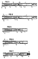
- FIGS. 3 to 7 show different variants of the contact component, which are combined from the same basic elements are.
- the contact component from FIG. 3 corresponds in all elements the contact component according to Figure 1.
- the contact piece 12 is on the contact parts 2 of the upper row stated.
- the outgoing lines are not shown Cable connector assigned to the contact pieces 12 is attachable.
- the contact springs 7 of the upper and lower Row each form the isolating contact in pairs, the by sliding an isolating plug from the operating side forth can be separated, making the wiring is interrupted. By means of the additional spring 3 and Additional housing part 4 can be the back of the protective plug be scheduled.
- the contact piece 12 is omitted.
- the arriving and outgoing lines are to the top and bottom Rows of connectors 5 connected and over the Separating contact of the contact springs 7 connected to each other.
- the cable connector is not required.
- the additional spring 3 and the additional housing part 4 make this possible Connect the protective plug to the back of the contact component.
- Figure 6 corresponds to the contact component of Figure 4 without the Additional spring 3 and the additional housing part 4.
- the contact parts in the upper row are omitted.
- the contact parts of the bottom row are with the Provide contact pieces 12 to which the cable connector 15 with the incoming lines 6 is attached.
- the arriving and outgoing lines 6 are not separable here.
Landscapes
- Computer Networks & Wireless Communication (AREA)
- Engineering & Computer Science (AREA)
- Connector Housings Or Holding Contact Members (AREA)
- Input Circuits Of Receivers And Coupling Of Receivers And Audio Equipment (AREA)
- Coupling Device And Connection With Printed Circuit (AREA)
- Exchange Systems With Centralized Control (AREA)
- Acyclic And Carbocyclic Compounds In Medicinal Compositions (AREA)
- Details Of Connecting Devices For Male And Female Coupling (AREA)
- Coin-Freed Apparatuses For Hiring Articles (AREA)
- Connections Arranged To Contact A Plurality Of Conductors (AREA)
- Structure Of Telephone Exchanges (AREA)
- Liquid Developers In Electrophotography (AREA)
- Types And Forms Of Lifts (AREA)
Description
- Figur 1
- einen Längsschnitt durch ein stapelbares Kontaktbauteil für einen Verteiler einer Telekommunikationsanlage,
- Figur 2
- eine Draufsicht auf das Kontaktbauteil nach Figur 1,
- Figur 3
- bis 7 schematisierte Längsschnitte durch unterschiedliche Varianten des Kontaktbauteils nach Figur 1.
Claims (7)
- Kontaktbauteil für einen Verteiler in einer Telekommunikationsanlage, wobei das scheibenartig flache stapelbare Kontaktbauteil mit einem aus Isolierstoff bestehenden Gehäuse versehen ist, das Aufnahmen für zwei parallele Reihen von Kontaktteilen (2) aufweist, die bedienungsseitig als Anschlußelemente (5) für ankommende und/oder abgehende elektrische Leitungen (6) ausgebildet sind und die von der Bedienungseite aus in das Innere des Kontaktbauteils ragen und dort Kontaktfedern (7) aufweisen, wobei jeweils ein Paar von den Kontaktfedern (7) aus beiden Reihen wechselweise über trennbare Kontaktstellen miteinander verbunden sind und wobei von einer Reihe der Kontaktteile zusätzliche Kontaktstücke in die Richtung der der Bedienungsseite gegenüberliegenden Rückseite abgezweigt sind und an ihrem freien Ende Steckkontakte (z.B. 12) für von der Rückseite her aufsteckbare Steckverbinder (z.B. 15) bilden,
dadurch gekennzeichnet, daß das Kontaktbauteil zwischen den trennbaren Kontaktstellen und den Steckkontakten (12) jeweils eine Zwischenwand (13) aufweist, die mit einer Öffnung zum Durchstecken und Durchführen des als Stiftkontakt ausgebildeten Kontaktstücks (12) versehen ist und daß das Gehäuse (1) mit Führungsformen für den Kabelstecker versehen ist. - Kontaktbauteil nach Anspruch 1,
dadurch gekennzeichnet, daß die Kontaktfeder (7) als fingerartiger Lappen ausgebildet ist, der aus einem inneren Endabschnitt des Kontaktteils (2) freigeschnitten und herausgebogen ist, daß seitlich der Kontaktfedern (7) stehengebliebene Stege (9) mit einem am inneren Ende des Kontaktteils (2) angeordneten Quersteg (11) einen geschlossenen Rahmenabschnitt (8) bilden, der sich auf der der Kontaktstelle der Kontaktfeder (7) abgewandten Seite am Gehäuse (1) abstützt. - Kontaktbauteil nach Anspruch 2,
dadurch gekennzeichnet, daß das Kontaktstück (12) einstückig mit dem Kontaktteil (2) verbunden ist und am Quersteg (11) des Rahmens (8) angesetzt ist,
daß das Kontaktstück (12) vom Quersteg (11) aus in einer Doppelbiegung in die Mittelebene des Gehäuses (1) gebogen ist. - Kontaktbauteil nach Anspruch 1, 2, oder 3,
dadurch gekennzeichnet, daß an das Gehäuse (1) rückseitig ein zusätzliches Gehäuseteil (4) ansetzbar ist, das Aufnahmen für Zusatzfedern (3) aufweist, die mit dem Kontaktteil 2 kontaktierbar sind und die rückseitig Steckkontaktstellen (20) für zusätzlich zu den Kabelsteckern ansetzbaren Schutzstecker aufweisen. - Kontaktbauteil nach Anspruch 4,
dadurch gekennzeichnet, daß das Gehäuse (1) und das zusätzliche Gehäuseteil (4) mittels wechselseitig angeordneter Rasthaken (21) und Rastschultern sowie Zentrierzapfen (22) und Zentrierlöchern verbunden sind, und
daß die fingerartigen Rasthaken (21) und die Zentrierzapfen (22) am zusätzlichen Gehäuseteil angebracht sind. - Kontaktbauteil nach einem der vorhergehenden Ansprüche,
dadurch gekennzeichnet, daß die Zusatzfeder (3) am Rahmenabschnitt (8) des Kontaktteils (2) lösbar anliegt und in ihrem Kontaktierbereich zum Kontaktteil (2) unter Vorspannung federnd auslenkbar ausgebildet und gelagert ist und in einem Zwischenraum zwischen dem Rahmenabschnitt (8) und einer äußeren Gehäusewand (19) einsteckbar ist. - Kontaktbauteil nach Anspruch 6,
dadurch gekennzeichnet, daß auf der der Zusatzfeder abgewandten Seite des Rahmenabschnitts (8) am Gehäuse (1) seitlich der Kontaktfeder (7) Auflagestege (10) für den Rahmenabschnitt (8) des Kontaktteils angeordnet sind und daß die Zusatzfeder (4) in ihrem Kontaktierbereich durch einen Längsschlitz gabelartig in zwei Schenkel (18) geteilt ist, die auf den seitlichen Stegen (9) des Rahmenabschnitts (8) aufliegen.
Applications Claiming Priority (3)
| Application Number | Priority Date | Filing Date | Title |
|---|---|---|---|
| DE4430794 | 1994-08-30 | ||
| DE4430794 | 1994-08-30 | ||
| PCT/DE1995/001112 WO1996007280A1 (de) | 1994-08-30 | 1995-08-22 | Kontaktbauteil für einen verteiler in einer telekommunikationsanlage |
Publications (2)
| Publication Number | Publication Date |
|---|---|
| EP0777947A1 EP0777947A1 (de) | 1997-06-11 |
| EP0777947B1 true EP0777947B1 (de) | 2003-08-13 |
Family
ID=6526940
Family Applications (1)
| Application Number | Title | Priority Date | Filing Date |
|---|---|---|---|
| EP95928962A Expired - Lifetime EP0777947B1 (de) | 1994-08-30 | 1995-08-22 | Kontaktbauteil für einen verteiler in einer telekommunikationsanlage |
Country Status (11)
| Country | Link |
|---|---|
| EP (1) | EP0777947B1 (de) |
| JP (1) | JPH10504947A (de) |
| CN (1) | CN1097966C (de) |
| AT (1) | ATE247365T1 (de) |
| AU (1) | AU685664B2 (de) |
| DE (1) | DE59510765D1 (de) |
| HU (1) | HU217723B (de) |
| NO (1) | NO970953D0 (de) |
| PL (1) | PL318781A1 (de) |
| WO (1) | WO1996007280A1 (de) |
| ZA (1) | ZA957226B (de) |
Families Citing this family (1)
| Publication number | Priority date | Publication date | Assignee | Title |
|---|---|---|---|---|
| AU7519498A (en) * | 1997-03-12 | 1998-09-29 | Rxs Kabelgarnituren Gmbh | Contact component for a distributor in a telecommunications installation |
Family Cites Families (5)
| Publication number | Priority date | Publication date | Assignee | Title |
|---|---|---|---|---|
| DE3614592C1 (de) * | 1986-04-30 | 1987-07-23 | Krone Ag | Anschlussleiste fuer Kabeladern,insbesondere von Fernsprechkabeln |
| ES2040374T3 (es) * | 1987-06-05 | 1993-10-16 | Krone Aktiengesellschaft | Linea terminal para pares de cable de la tecnica de la telecomunicacion. |
| CN1047421A (zh) * | 1989-05-18 | 1990-11-28 | 纳幕尔杜邦公司 | 具有高密度表面安装的接触元件的组合式接插件系统 |
| JPH05505056A (ja) * | 1990-03-14 | 1993-07-29 | シーメンス アクチエンゲゼルシヤフト | 通信ネットワークにおける分配器のための接触機構部品 |
| DE9213947U1 (de) * | 1992-10-15 | 1992-11-26 | Siemens AG, 8000 München | Schichtbaustein für Verteiler in einer Telekommunikationsanlage |
-
1995
- 1995-08-22 JP JP8508404A patent/JPH10504947A/ja active Pending
- 1995-08-22 EP EP95928962A patent/EP0777947B1/de not_active Expired - Lifetime
- 1995-08-22 CN CN95195771A patent/CN1097966C/zh not_active Expired - Fee Related
- 1995-08-22 HU HU9702138A patent/HU217723B/hu not_active IP Right Cessation
- 1995-08-22 AT AT95928962T patent/ATE247365T1/de not_active IP Right Cessation
- 1995-08-22 WO PCT/DE1995/001112 patent/WO1996007280A1/de not_active Ceased
- 1995-08-22 DE DE59510765T patent/DE59510765D1/de not_active Expired - Lifetime
- 1995-08-22 AU AU32522/95A patent/AU685664B2/en not_active Ceased
- 1995-08-22 PL PL95318781A patent/PL318781A1/xx unknown
- 1995-08-29 ZA ZA957226A patent/ZA957226B/xx unknown
-
1997
- 1997-02-28 NO NO970953A patent/NO970953D0/no not_active Application Discontinuation
Also Published As
| Publication number | Publication date |
|---|---|
| AU685664B2 (en) | 1998-01-22 |
| PL318781A1 (en) | 1997-07-07 |
| AU3252295A (en) | 1996-03-22 |
| EP0777947A1 (de) | 1997-06-11 |
| HUT77159A (hu) | 1998-03-02 |
| CN1161769A (zh) | 1997-10-08 |
| WO1996007280A1 (de) | 1996-03-07 |
| DE59510765D1 (de) | 2003-09-18 |
| HU217723B (hu) | 2000-04-28 |
| ZA957226B (en) | 1996-04-01 |
| NO970953L (no) | 1997-02-28 |
| JPH10504947A (ja) | 1998-05-12 |
| ATE247365T1 (de) | 2003-08-15 |
| CN1097966C (zh) | 2003-01-01 |
| NO970953D0 (no) | 1997-02-28 |
Similar Documents
| Publication | Publication Date | Title |
|---|---|---|
| DE2804478C2 (de) | Elektrischer Klemmverbinder zur löt-, schraub- und abisolierfreien Herstellung eines Kontaktes an einem feststehenden Anschlußelement, insbesondere für die Fernmeldelinientechnik | |
| EP0302814B1 (de) | Anschlussleiste der Fernmeldetechnik | |
| CH625364A5 (de) | ||
| DE3807645C2 (de) | Steckverbindungssystem für elektrische Leiter | |
| DE2443476C2 (de) | Elektrisches Verbindungsstück | |
| DE102007053722B4 (de) | Hermaphroditischer Steckverbinder | |
| DE4229279A1 (de) | Verbinder | |
| DE102004054203A1 (de) | Schneidklemm-Steckkontaktleiste für elektrische Steckverbinder | |
| DE3318137C2 (de) | Mehrpolige elektrische Steckvorrichtung | |
| DE60222034T2 (de) | Elektrische Steckverbinderanordnung | |
| DE8530054U1 (de) | Elektrischer Stecker | |
| DE69407501T2 (de) | Vertikal ausgerichtete elektrische abgeschirmte Verbinderbauteile | |
| EP1117158A2 (de) | Vorrichtung zur Schirmung für Anschlussleisten | |
| DE2712723C2 (de) | Elektrischer Verteiler | |
| EP0777947B1 (de) | Kontaktbauteil für einen verteiler in einer telekommunikationsanlage | |
| DE69800453T2 (de) | Schraubklemme und Anschlussleiste für einen elektrischen Apparat | |
| DE2714158C3 (de) | Anschlußvorrichtung für ein vieladriges Rundkabel | |
| DE2213747A1 (de) | Elektrische Steckverbindung | |
| DE2843095A1 (de) | Elektrische anschlussfassung | |
| DE19721501B4 (de) | Verbinder zur Herstellung einer Querverbindung zwischen ausgerichteten modularen, elektrischen Vorrichtungen | |
| DE10238852B3 (de) | Schaltgerät | |
| DE102009024330A1 (de) | Anschlussleiste | |
| DE2643150A1 (de) | Verteileranordnung fuer fernmeldevermittlungsanlagen | |
| DE1765854B2 (de) | AnschluBvorrichtung für eine am Rand mit elektrischen Leiterbahnen versehene Platine | |
| DE4430797C1 (de) | Kontaktbauteil für einen Verteiler in einer Telekommunikationsanlage |
Legal Events
| Date | Code | Title | Description |
|---|---|---|---|
| PUAI | Public reference made under article 153(3) epc to a published international application that has entered the european phase |
Free format text: ORIGINAL CODE: 0009012 |
|
| 17P | Request for examination filed |
Effective date: 19970206 |
|
| AK | Designated contracting states |
Kind code of ref document: A1 Designated state(s): AT BE DE PT |
|
| GRAH | Despatch of communication of intention to grant a patent |
Free format text: ORIGINAL CODE: EPIDOS IGRA |
|
| GRAH | Despatch of communication of intention to grant a patent |
Free format text: ORIGINAL CODE: EPIDOS IGRA |
|
| GRAA | (expected) grant |
Free format text: ORIGINAL CODE: 0009210 |
|
| RAP1 | Party data changed (applicant data changed or rights of an application transferred) |
Owner name: CCS TECHNOLOGY, INC. |
|
| AK | Designated contracting states |
Designated state(s): AT BE DE PT |
|
| PG25 | Lapsed in a contracting state [announced via postgrant information from national office to epo] |
Ref country code: AT Free format text: LAPSE BECAUSE OF NON-PAYMENT OF DUE FEES Effective date: 20030822 |
|
| REF | Corresponds to: |
Ref document number: 59510765 Country of ref document: DE Date of ref document: 20030918 Kind code of ref document: P |
|
| PG25 | Lapsed in a contracting state [announced via postgrant information from national office to epo] |
Ref country code: PT Free format text: LAPSE BECAUSE OF FAILURE TO SUBMIT A TRANSLATION OF THE DESCRIPTION OR TO PAY THE FEE WITHIN THE PRESCRIBED TIME-LIMIT Effective date: 20040113 |
|
| PLBE | No opposition filed within time limit |
Free format text: ORIGINAL CODE: 0009261 |
|
| STAA | Information on the status of an ep patent application or granted ep patent |
Free format text: STATUS: NO OPPOSITION FILED WITHIN TIME LIMIT |
|
| 26N | No opposition filed |
Effective date: 20040514 |
|
| PGFP | Annual fee paid to national office [announced via postgrant information from national office to epo] |
Ref country code: BE Payment date: 20080922 Year of fee payment: 14 |
|
| BERE | Be: lapsed |
Owner name: *CCS TECHNOLOGY INC. Effective date: 20090831 |
|
| PG25 | Lapsed in a contracting state [announced via postgrant information from national office to epo] |
Ref country code: BE Free format text: LAPSE BECAUSE OF NON-PAYMENT OF DUE FEES Effective date: 20090831 |
|
| PGFP | Annual fee paid to national office [announced via postgrant information from national office to epo] |
Ref country code: DE Payment date: 20120829 Year of fee payment: 18 |
|
| PG25 | Lapsed in a contracting state [announced via postgrant information from national office to epo] |
Ref country code: DE Free format text: LAPSE BECAUSE OF NON-PAYMENT OF DUE FEES Effective date: 20140301 |
|
| REG | Reference to a national code |
Ref country code: DE Ref legal event code: R119 Ref document number: 59510765 Country of ref document: DE Effective date: 20140301 |