EP0777757B1 - Inversionsgiesseinrichtung mit kristallisator - Google Patents
Inversionsgiesseinrichtung mit kristallisator Download PDFInfo
- Publication number
- EP0777757B1 EP0777757B1 EP95921701A EP95921701A EP0777757B1 EP 0777757 B1 EP0777757 B1 EP 0777757B1 EP 95921701 A EP95921701 A EP 95921701A EP 95921701 A EP95921701 A EP 95921701A EP 0777757 B1 EP0777757 B1 EP 0777757B1
- Authority
- EP
- European Patent Office
- Prior art keywords
- inversion
- means according
- casting means
- vessel
- nozzles
- Prior art date
- Legal status (The legal status is an assumption and is not a legal conclusion. Google has not performed a legal analysis and makes no representation as to the accuracy of the status listed.)
- Expired - Lifetime
Links
- 238000005266 casting Methods 0.000 title claims abstract description 26
- 239000000155 melt Substances 0.000 claims abstract description 19
- 239000002184 metal Substances 0.000 claims description 18
- 238000007789 sealing Methods 0.000 claims 2
- 230000005611 electricity Effects 0.000 claims 1
- 239000011819 refractory material Substances 0.000 claims 1
- 239000000758 substrate Substances 0.000 abstract 2
- 239000000945 filler Substances 0.000 description 7
- 229910001338 liquidmetal Inorganic materials 0.000 description 6
- 238000009826 distribution Methods 0.000 description 4
- 238000002425 crystallisation Methods 0.000 description 3
- 230000008025 crystallization Effects 0.000 description 3
- 238000002844 melting Methods 0.000 description 3
- 230000008018 melting Effects 0.000 description 3
- 229910000831 Steel Inorganic materials 0.000 description 2
- 238000001816 cooling Methods 0.000 description 2
- 238000011161 development Methods 0.000 description 2
- 230000018109 developmental process Effects 0.000 description 2
- 239000007788 liquid Substances 0.000 description 2
- 230000001105 regulatory effect Effects 0.000 description 2
- 239000010959 steel Substances 0.000 description 2
- 238000010276 construction Methods 0.000 description 1
- 238000010586 diagram Methods 0.000 description 1
- 238000010438 heat treatment Methods 0.000 description 1
- 230000001788 irregular Effects 0.000 description 1
- 238000004519 manufacturing process Methods 0.000 description 1
- 239000000203 mixture Substances 0.000 description 1
- 230000000284 resting effect Effects 0.000 description 1
- 230000007704 transition Effects 0.000 description 1
- 238000005406 washing Methods 0.000 description 1
Images

Classifications
-
- B—PERFORMING OPERATIONS; TRANSPORTING
- B22—CASTING; POWDER METALLURGY
- B22D—CASTING OF METALS; CASTING OF OTHER SUBSTANCES BY THE SAME PROCESSES OR DEVICES
- B22D11/00—Continuous casting of metals, i.e. casting in indefinite lengths
- B22D11/14—Plants for continuous casting
- B22D11/145—Plants for continuous casting for upward casting
-
- B—PERFORMING OPERATIONS; TRANSPORTING
- B22—CASTING; POWDER METALLURGY
- B22D—CASTING OF METALS; CASTING OF OTHER SUBSTANCES BY THE SAME PROCESSES OR DEVICES
- B22D11/00—Continuous casting of metals, i.e. casting in indefinite lengths
- B22D11/008—Continuous casting of metals, i.e. casting in indefinite lengths of clad ingots, i.e. the molten metal being cast against a continuous strip forming part of the cast product
Definitions
- the invention relates to an inversion casting device with a crystallizer which has a slot-shaped passage arranged in the bottom and provided with a seal for the passage of a carrier tape and which is connected to a melt feed.
- inversion casting an uncooled, cleaned metal profile with a low heat content is passed through molten metal located in a melting tank. When the metal wire or metal strand comes into contact, the molten metal crystallizes on the relatively cool metal profile. The crystallization thickness depends on the length of the contact time and the temperatures of the metal profile and the metal melt. From US 3466186 an inversion casting device is known in which a wire is drawn through a container filled with melt. The container has a sealable passage in the bottom area.
- the supply of the melt to the container is provided in the vicinity of the bath level.
- the wire provided for crystallization is surrounded by a sleeve which has passages in the bottom region of the melt container through which liquid metal is fed to the wire.
- EP 0 311 602 B1 discloses a method for producing thin metal strands, in which the carrier tape is likewise pulled upwards through the liquid melt through the bottom of a melting container in a vertical direction. In both writings, the wire or ribbon is passed through the resting bath of the molten metal. When the carrier element comes into contact with the melt, an irregular flow profile is formed which cannot be influenced from the outside. Depending on this unfavorable flow profile, there is an uneven temperature distribution, especially when inversion casting strips.
- the invention has set itself the goal of creating a crystallization device for dimensionally accurate strips in which the relative speed of the strand and the molten steel near the strand is small in order to achieve a constant growth rate of the metal and in which the molten steel in the crystallizer has a uniform temperature distribution.
- the invention achieves this aim by the characterizing features of claim 1.
- Advantageous further developments are shown in the subclaims.
- the inversion casting device according to the invention has a crystallizer in which a template is provided which extends horizontally into the vessel near the bottom. Nozzles lead from the template to the interior of the vessel. The nozzle orifices are arranged so that the outflowing melt strikes the carrier tape at a flat angle in the tape take-off direction.
- the liquid metal flowing out of the nozzles forms a speed profile which can be set so that the liquid has the same speed as the carrier tape. Downstream, the bath movement in the vicinity of the carrier tape is no longer moved by the metal flowing out of the nozzles, but by the carrier tape itself.
- the liquid metal moving at the same speed as the carrier tape has the possibility of crystallizing at a relative speed of close to 0. Through the targeted feeding of the molten metal through nozzles, a uniform temperature distribution of the melt is achieved. This safe temperature control prevents damage, in particular melting of the carrier tape.
- the avoidance of a relative speed kit and the even distribution of the temperature lead to a constant increase in the thickness of the carrier tape over its width.
- the proposed crystallizer has geometrically simple shapes and is low-wear due to its shape adapted to the flow conditions of the liquid metal.
- the nozzles are slit-shaped or tubular and are guided so that the angle of inclination between them and the carrier tape is less than 30 °.
- the choice of the angle of inclination and the proposed shapes result in a stable refractory structure which has sufficient passage space so that there is no obstruction to the metal flow.
- a thickness / length ratio of 1/10 to 1/30 is proposed for the slot-shaped nozzles, and a diameter of 20 to 40 mm for the tubular nozzles. Both nozzle shapes make it possible to generate a homogeneous flow profile of the melt on the carrier belt.
- the template is in the form of a sleeve which is separated from the carrier tape by a shield. Crossovers are provided in the foot area as well as in the head area.
- the arrangement of the shields enables particularly precise guidance of the melt through the channel formed between the carrier tape and the shield.
- the transition in the head area of the shields gives the metal the opportunity to overflow and mix with the newly added metal.
- both the temperature and the quality of the liquid metal are set in a special way.
- By arranging elements for setting the temperature in the shields it is possible to drive exactly a predetermined and desired temperature. It is also proposed to use electrically powered coils in the outer walls of the crystallizer vessel to increase the flow rate. Constant conditions are also achieved through the use of a mold level control. This can be achieved in a simple manner by supplying mixed melt from the pan via a filler neck for introducing the crystallizer.
- the interior of the vessel is adapted to the flow conditions, in such a way that, in particular, the shields are at a greater distance in the area of the shield heads in the pull-off direction of the carrier tape.
- the carrier tape is so far from the outer walls or shields that the flow of the melt is not hindered. The distance here is around 20 to 80 mm depending on the belt size and speed.
- the crystallizer is constructed so that the individual Vessel parts consist of components that are prefabricated and on site easy to change. Because the template is the parts with the highest Have susceptibility to wear, especially above Horizontal blanket cut provided. The single ones Components can be attached to the metal jacket of the vessel Loosen the provided clamping devices and close them tightly again connect.
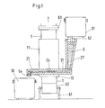
- FIG. 1 shows a vessel 11 through which a carrier tape T, which on Vessel bottom enters, is guided.
- the carrier tape T is on a arranged under the vessel 11 tape roll 62 which on a Stand 61 is mounted, and is by a above the vessel 11th provided take-off roller 63 promoted.
- the vessel 11 is in its lower region from a template 21 surround which melt feed side a filler neck 27 and has an emergency stopper 54 on the melt discharge side.
- a feed pan 51 Above the Filler neck 27, a feed pan 51 is positioned, the one Immersed tube 52, which in the mouth of the filler neck 27th In the area of the vessel 11, the template 21 points in the Figure shows sketchy slot-shaped nozzles 24.
- the Melt is marked with S.
- FIG. 2 a longitudinal section through the vessel 11 is shown, through which a carrier tape T is guided through a melt S.
- the vessel 11 has a jacket 15 which is provided with a refractory lining 16.
- the vessel 11 has separating cuts 41. On the outside of the vessel 41 clamping elements 42 are provided in the region of the separating cuts, which join the individual vessel parts 19 together.
- a passage 13 is provided in the vessel bottom 12, which provides a seal 14 has.
- the lower part of the vessel 11 is designed as a template 21 which has nozzles 23, the mouth 26 of which is connected to the interior 17 of the vessel.
- the nozzles 23 are designed as slot-shaped nozzles 24 and on the left side as tubular nozzles 25.
- the angle of inclination of the nozzles 23 is ⁇ 30 °.
- the section BB is laid through the template 21, which is shown in the lower part of FIG. 2 as a top view. From the filler neck, not shown here, melt flows into the annular template 21, via which the melt can reach the carrier tape T located in the center of the vessel 11. In emergencies, the melt located in the vessel and in the filler neck can be drained off via an only indicated outlet.
- the template 21 provided in the refractory lining 16, which is enveloped by a metallic jacket 15, is designed in a ring shape.
- the nozzle 23 is designed as a slot-shaped nozzle 24.
- the nozzle 24 can be interrupted by support walls 28.
- the nozzle 23 is formed by tubular nozzles 25.
- the individual tubular nozzles 25 are connected to a template guided parallel to the interior 17 of the vessel, and a central template is provided in the lower area.
- the arrows shown in the top view show the direction of flow of the liquid metal.
- the dash-dotted arrows apply in the event that an emergency pan is connected and the crystallizer is to be emptied.
- the crystallizer can be filled with melt from one side or from two sides.
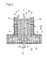
- FIG. 3 shows a vessel 11 with a refractory lining 16 which is enveloped by a jacket 15.
- Shields 31 are located in the interior 17 of the vessel intended. which are arranged so that a sleeve-shaped template 22nd is present.
- the shields 31 have a size that with Melt S filled vessel overflow this at an overflow 32 can.
- the shield 31 On the left side of the picture, the shield 31 has a conically tapering cross section, so that the melt flowing with the carrier tape 15 is not hindered. Furthermore, elements 33 for regulating the temperature are provided in the shields 31, so here, for example, cooling tube coils arranged in a meandering manner can be introduced, through which a cooling or heating medium can be guided.
- the refractory lining 16 is parallel to the shields 31 coils 34 are provided, through which the flow of Melt S can be influenced.
- the passage 13 is provided in the vessel bottom 12 and prevents the melt S from escaping from the vessel 11 by means of a seal 14.
Landscapes
- Engineering & Computer Science (AREA)
- Mechanical Engineering (AREA)
- Continuous Casting (AREA)
- Crystals, And After-Treatments Of Crystals (AREA)
- Saccharide Compounds (AREA)
- Coating With Molten Metal (AREA)
- Casting Support Devices, Ladles, And Melt Control Thereby (AREA)
- External Artificial Organs (AREA)
- Extrusion Moulding Of Plastics Or The Like (AREA)
- Confectionery (AREA)
Description
Beim Inversionsgießen wird ein ungekühltes, gereinigtes Metallprofil niedrigen Wärmeinhaltes durch in einem Schmelzbehälter befindliche Metallschmelze geführt. Bei dem Kontakt des Metalldrahtes oder Metallstranges kristallisiert die Metallschmelze an dem relativ kühlen Metallprofil an. Die Ankristallisationsdicke ist abhängig von der Länge der Kontaktzeit sowie den Temperaturen des Metallprofils und der Metallschmelze.
Aus der Schrift US 3466186 ist eine Inversionsgießeinrichtung bekannt, bei der ein Draht durch einen mit Schmelze gefüllten Behälter hindurchgezogen wird. Der Behälter besitzt im Bodenbereich einen abdichtbaren Durchtritt. Die Zufuhr der Schmelze zum Behälter ist in der Nähe des Badspiegels vorgesehen. In einer besonderen ausführungsform wird der zum Ankristallisieren vorgesehene Draht von einer Hülse umgeben, die im Bodenbereich des Schmelzenbehälters Durchtritte aufweist, durch die Flüssigmetall dem Draht zugeführt wird. Weiterhin ist aus der EP 0 311 602 B1 ein Verfahren zum Erzeugen von dünnen Metallsträngen bekannt, bei dem ebenfalls durch den Boden eines Schmelzbehälters das Trägerband in vertikaler Richtung nach oben durch die Flüssigschmelze gezogen wird.
In beiden Schriften wird der Draht oder das Band durch das ruhende Bad der Metallschmelze geführt. Bei dem Kontakt des Trägerelementes und der Schmelze bildet sich ein unregelmaßiges und von außen nicht beeinflußbares Strömungsprofil aus. In Abhängigkeit dieses ungünstigen Strömungsprofils kommt es zu einer ungleichmäßigen Temperaturverteilung, insbesondere beim Inversionsgießen von Bändern.
Die Erfindung erreicht dieses Ziel durch die kennzeichnenden Merkmale des Anspruchs 1. In den Unteransprüchen sind vorteilhafte Weiterbildungen aufgezeigt.
Die erfindungsgemäße Inversionsgießeinrichtung weist einen Kristallisator auf, bei dem eine in das Gefäß in Bodennähe horizontal umgreifende Vorlage vorgesehen ist. Von der Vorlage führen Düsen zum Gefäßinnenraum. Die Düsenmündungen sind dabei so angeordnet, daß die ausströmende Schmelze in einem flachen Winkel in Bandabzugsrichtung auf das Trägerband auftrifft. Durch das aus den Düsen strömende Flüssigmetall bildet sich ein Geschwindigkeitsprofil, das so eingestellt werden kann, daß die Flüssigkeit die gleiche Geschwindigkeit wie das Trägerband aufweist. Stromabwärts wird die Badbewegung in Nähe des Trägerbandes nicht mehr durch das aus den Düsen ausströmende Metall, sondern durch das Trägerband selber bewegt.
Das mit gleicher Geschwindigkeit wie das Trägerband sich bewegende Flüssigmetall hat die Möglichkeit, bei einer Relativgeschwindigkeit von nahe zu 0 an zu kristallisieren.
Durch das gezielte Zuführen der Metallschmelze über Düsen wird eine gleichmäßige Temperaturverteilung der Schmelze erreicht. Durch diese sichere Temperaturführung werden Beschädigungen, insbesondere ein Aufschmelzen des Trägerbandes vermieden.
Das Vermeiden einer Relativgeschwindigkit und das gleichmäßige Verteilen der Temperatur führen zu einem konstanten Anwachsen der Dicke des Trägerbandes über seine Breite.
Der vorgeschlagene Kristallisator weist geometrisch einfache Formen auf und ist durch seine den Strömungsverhältnissen des Flüssigmetalls angepaßte Form verschleißarm.
Bei den schlitzförmigen Düsen wird ein Dicken-/Längenverhältnis von 1/10 bis 1/30, bei den rohrförmigen Düsen ein Durchmesser von 20 bis 40 mm vorgeschlagen. Beide Düsenformen ermöglichen es, ein homogenes Strömungsprofil der Schmelze auf dem Trägerband zu erzeugen.
In einer vorteilhaften Weiterbildung ist die Vorlage in Form einer Hülse ausgebildet, die durch ein Schild vom Trägerband getrennt ist. Im Fußbereich wie auch im Kopfbereich sind Übertritte vorgesehen. Durch die Anordnung der Schilde ist durch den zwischen dem Trägerband und dem Schild entstehenden Kanal eine besonders exakte Führung der Schmelze möglich. Durch den Übertritt im Kopfbereich der Schilde hat das Metall die Möglichkeit, überzuströmen und mit dem neu zugeführten Metall sich zu vermischen. Hierdurch wird in besonderer Weise sowohl die Temperatur wie auch die Qualität des Flüssigmetalls eingestellt.
Durch Anordnung von Elementen zur Einstellung der Temperatur in den Schilden ist es möglich, exakt eine vorgebbare und gewünschte Temperatur zu fahren.
Weiterhin wird vorgeschlagen, in den Außenwänden des Kristallisatorgefäßes zur Erhöhung der Stromungsgeschwindigkeit elektrisch gespeiste Spulen einzusetzen.
Konstante Verhältnisse werden darüber hinaus noch erreicht durch den Einsatz einer Gießspiegelregelung. In einfacher Weise läßt sich dies erreichen durch Mischschmelzenzufuhr von der Pfanne über einen Einfüllstutzen zur Vorlage des Kristallisators. Durch die Anordnung des Zufuhrtrichters und dem Gefäßinnenraum in Form der kommunizierenden Röhren wird mit einfachen Mitteln erreicht, von außen auf den Gießspiegel Einfluß zu nehmen.
In einer vorteilhaften Ausgestaltung wird der Gefäßinnenraum den Strömungsverhältnissen angepaßt, und zwar in der Weise, daß insbesondere die Schilde in Abzugsrichtung des Trägerbandes im Bereich der Schildköpfe einen größeren Abstand aufweisen. Insgesamt ist das Trägerband dabei von den Außenwandungen bzw. Schilden soweit beabstandet, daß die Strömung der Schmelze nicht behindert wird. Der Abstand beträgt hier in Abhängigkeit von Bandgröße und -geschwindigkeit etwa 20 bis 80 mm.
Das Gefäß 11 weist dabei Trennschnitte 41 auf. An der Außenseite des Gefäßes sind im Bereich der Trennschnitte 41 Klemmelemente 42 vorgesehen, die die einzelnen Gefäßteile 19 aneinanderfügen.
Durch die Vorlage 21 ist der Schnitt BB gelegt, der im unteren Teil der Figur 2 als Draufsicht dargestellt ist.
Vom hier nicht weiter dargestellten Einfüllstutzen strömt Schmelze in die ringförmige Vorlage 21, über die Schmelze zum im Zentrum des Gefäßes 11 sich befindenen Trägerbandes T gelangen kann. In Notfällen kann die sich im Gefäß und im Einfüllstutzen befindliche Schmelze über einen nur angedeuteten Auslaß abgelassen werden.
Die in der Feuerfestauskleidung 16, welche von einem metallischen Mantel 15 umhüllt ist, vorgesehene Vorlage 21 ist ringförmig ausgestaltet. Auf der rechten Seite der Draufsicht ist die Düse 23 als schlitzförmige Düse 24 ausgebildet. Aus stabilitätsgründen kann die Düse 24 durch Stützwände 28 unterbrochen sein.
Auf der linken Seite der Draufsicht wird die Düse 23 durch rohrförmige Düsen 25 gebildet. Im oberen Teil der linken Seite sind die einzelnen rohrförmigen Düsen 25 an eine parallel zum Gefäßinnenraum 17 geführten Vorlage verbunden, im unteren Bereich ist eine zentrale Vorlage vorgesehen. Die in der Draufsicht dargestellten Pfeile zeigen die Strömungsrichtung des flüssigen Metalls. Die strichpunktierten Pfeile gelten für den Fall, daß eine Notpfanne angeschlossen ist und der Kristallisator entleert werden soll.
Der Kristallisator kann von einer Seite oder aber auch von zwei Seiten mit Schmelze gefüllt werden.
Weiterhin sind in den Schilden 31 Elemente 33 zur Regelung der Temperatur vorgesehen, so können hier beispielsweise meanderförmig angeordnete Kühlrohrschlangen eingebracht werden, durch die ein Kühl- oder Heizmittel führbar ist.
Im Gefäßboden 12 ist der Durchtritt 13 vorgesehen, der durch eine Abdichtung 14 ein Auslaufen der Schmelze S aus dem Gefäß 11 verhindert.
- 11.
- Gefäß
- 12
- Gefäßboden
- 13
- Durchtritt
- 14
- Abdichtung
- 15
- Mantel
- 16
- Feuerfestauskleidung
- 17
- Gefäßinnenraum
- 19
- Gefäßteil
Schmelzenführung - 21
- Vorlage (ringförmig)
- 22
- Vorlage (hülsenförmig)
- 23
- Düsen
- 24
- schlitzförmige Düse
- 25
- rohrförmige Düse
- 26
- Mündung
- 27
- Einfüllstutzen
- 28
- Stützwand
- 29
- Vorlagendecke
Strömungskörper - 31
- Schild
- 32
- Überlauf
- 33
- Elemente zur Regelung der Temperatur
- 34
- Spulen
Baukasten - 41
- Trennschnitt
- 42
- Klemmelement
Pfanne - 51
- Zufuhrpfanne
- 52
- Tauchrohr
- 53
- Notpfanne
- 54
- Notstopfen
Trägerbandführung - 61
- Ständer
- 62
- Bandrolle
- 63
- Abzugsrolle
- T
- Trägerband
- S
- Schmelze
- α
- Neigungswinkel
- D
- Durchmesserdüse
- d
- Dicke Trägerband
- B
- Abstand Schild/Trägerband
Claims (18)
- Inversionsgießeinrichtung mit Kristallisator, der einen im Boden angeordneten und mit einer Abdichtung versehenen schlitzförmigen Durchtritt zur Durchleitung eines Trägerbandes aufweist und der mit einer Schmelzenzuführung in Verbindung steht,
dadurch gekennzeichnet,daß eine das Kristallisatorgefäß (11) horizontal umgreifende Vorlage (21) vorgesehen ist,daß die Vorlage (21) mit im Bereich des Durchtritts (13) angeordneten Düsen (23) in Verbindung steht unddaß die Düsenmündungen (26) in der Weise angeordnet sind, daß die ausströmende Schmelze (S) in einem flachen Neigungswinkel α in Bandabzugsrichtung auf das Trägerband (T) auftrifft. - Inversionsgießeinrichtung nach Anspruch 1,
dadurch gekennzeichnet,daß der Neigungswinkel α zwiscnen der Düse (23) und dem Trägerband (T) kleiner 30 ° ist. - Inversionsgießeinrichtung nach Anspruch 2,
dadurch gekennzeichnet,daß die Düsen (23) schlitzförmig (24) ausgebildet sind und eine Dicke (D) von kleiner als das Dreifache der Austrittsdicke (d) des Trägerbandes (T) und einem Dicken-/Längenverhältnis von 1/10 bis 1/30 aufweist. - Inversionsgießeinrichtung nach Anspruch 3,
dadurch gekennzeichnet,daß mehrere schlitzförmige Düsen (24) über die Bandbreite vorgesehen sind, die durch Stützwände (28) getrennt sind. - Inversionsgießeinrichtung nach Anspuch 1,
dadurch gekennzeichnet,daß die Düsen (23) rohrförmig (25) ausgebildet sind und einen Durchmesser (D) zwischen 20 und 40 mm aufweisen. - Inversionsgießeinrichtung nach den Ansprüchen 3 oder 4,
dadurch gekennzeichnet,daß die Düsen (23) strömungsmäßig unmittelbar mit der einen Einfüllstutzen (27) aufweisenden Vorlage (21) verbunden sind. - Inversionsgießeinrichtung nach Anspruch 6,
dadurch gekennzeichnet,daß die Vorlage (21) in Form einer Hülse (22) ausgebildet ist, die durch einen die Düsen (23) aufweisenden Schild (31) vom Gefäßinnenraum (17) getrennt ist. - Inversionsgießeinrichtung nach Anspruch 7,
dadurch gekennzeichnet,daß der Schild (31) kopfendig Überläufe (32) besitzt, die mit der Vorlage (22) in Verbindung stehen. - Inversionsgießeinrichtung nach Anspruch 8,
dadurch gekennzeichnet,daß die Schilde (31) Elemente (33) zur Einstellung der Temperatur aufweisen. - Inversionsgießeinrichtung nach Anspruch 8,
dadurch gekennzeichnet,daß die Außenwände (18) des Gefäßes (1) elektrisch gespeiste Spulen (34) zur Erhöhung der Strömungsgeschwindigkeit der Metallschmelze (S) besitzen. - Inversionsgießeinrichtung nach Anspruch 8,
dadurch gekennzeichnet,daß die Schilde (31) in Abzugsrichtung des Trägerbandes (T) dem Gefäßinnenraum (17) zugeneigt sich öffnen. - Inversionsgießeinrichtung nach einem der o. g. Ansprüche,
dadurch gekennzeichnet,daß oberhalb der Vorlagendecke (29) mindestens ein horizontaler Trennschnitt (41) vorgesehen ist. - Inversionsgießeinrichtung nach Anspruch 12,
dadurch gekennzeichnet,daß am Gefäßmantel (15) zum flüssigkeitsdichten Verschließen des Trennschnittes (41) lösbare Klemmelemente (42) vorgesehen sind. - Inversionsgießeinrichtung nach Anspruch 13,
dadurch gekennzeichnet,daß die durch die Klemmelemente (42) lösbar vorhandenen Gefäßteile (19) vorgefertigte mit Feuerfestmaterial versehene Mantelstücke (15) sind. - Inversionsgießeinrichtung nach Anspruch 7,
dadurch gekennzeichnet,daß die Schilde (21) parallel zum Trägerband verlaufend in einem die Strömung der Schmelze (S) nicht behindernden Abstand (B) angeordnet sind. - Inversionsgießeinrichtung nach Anspruch 14,
dadurch gekennzeichnet,daß der Abstand (B) zwischen 20 und 80 mm liegt. - Inversionsgießeinrichtung nach Anspruch 8,
dadurch gekennzeichnet,daß die Vorlage (21) ein Notstopfen (54) aufweist, mit dem eine Notpfanne (53) in Verbindung bringbar ist. - Inversionsgießeinrichtung nach Anspruch 1,
dadurch gekennzeichnet,daß der Durchtritt (13) am Bandeinlauf durch eine Abdichtung (14) verschließbar ist, z. B. durch eine elektromagnetische Bremse.
Applications Claiming Priority (3)
| Application Number | Priority Date | Filing Date | Title |
|---|---|---|---|
| DE4426705A DE4426705C1 (de) | 1994-07-20 | 1994-07-20 | Inversionsgießeinrichtung mit Kristallisator |
| DE4426705 | 1994-07-20 | ||
| PCT/DE1995/000786 WO1996002683A1 (de) | 1994-07-20 | 1995-06-15 | Inversionsgiesseinrichtung mit kristallisator |
Publications (2)
| Publication Number | Publication Date |
|---|---|
| EP0777757A1 EP0777757A1 (de) | 1997-06-11 |
| EP0777757B1 true EP0777757B1 (de) | 1998-04-01 |
Family
ID=6524335
Family Applications (1)
| Application Number | Title | Priority Date | Filing Date |
|---|---|---|---|
| EP95921701A Expired - Lifetime EP0777757B1 (de) | 1994-07-20 | 1995-06-15 | Inversionsgiesseinrichtung mit kristallisator |
Country Status (15)
| Country | Link |
|---|---|
| US (1) | US5850869A (de) |
| EP (1) | EP0777757B1 (de) |
| JP (1) | JP3016595B2 (de) |
| CN (1) | CN1173208A (de) |
| AT (1) | ATE164631T1 (de) |
| AU (1) | AU689596B2 (de) |
| BR (1) | BR9508303A (de) |
| CA (1) | CA2194406A1 (de) |
| CZ (1) | CZ288271B6 (de) |
| DE (2) | DE4426705C1 (de) |
| ES (1) | ES2114324T3 (de) |
| MX (1) | MX9606086A (de) |
| RU (1) | RU2127167C1 (de) |
| WO (1) | WO1996002683A1 (de) |
| ZA (1) | ZA954612B (de) |
Families Citing this family (9)
| Publication number | Priority date | Publication date | Assignee | Title |
|---|---|---|---|---|
| CN1050157C (zh) * | 1996-05-27 | 2000-03-08 | 宝山钢铁(集团)公司 | 反向凝固复合板带连续生产方法 |
| DE19638905C1 (de) * | 1996-09-23 | 1998-01-02 | Schloemann Siemag Ag | Verfahren zur Erzeugung von beschichteten Metallsträngen, insbesondere Metallbändern und Beschichtungsanlage |
| CA2225537C (en) | 1996-12-27 | 2001-05-15 | Mitsubishi Heavy Industries, Ltd. | Hot dip coating apparatus and method |
| FR2798396A1 (fr) * | 1999-09-09 | 2001-03-16 | Lorraine Laminage | Dispositif de revetement au trempe de bandes metalliques en defilement |
| FR2804443A1 (fr) * | 2000-01-28 | 2001-08-03 | Usinor | Dispositif de revetement au trempe par un metal liquide d'une bande metallique en defilement ascendant |
| DE10014868A1 (de) * | 2000-03-24 | 2001-09-27 | Sms Demag Ag | Verfahren und Einrichtung zum Schmelztauchbeschichten von Metallsträngen, insbesondere von Stahlband |
| FI116453B (fi) * | 2000-12-20 | 2005-11-30 | Outokumpu Oy | Menetelmä kerrosmetallituoteaihion valmistamiseksi ja kerrosmetallituoteaihio |
| US9376739B2 (en) | 2012-03-23 | 2016-06-28 | Aleksandr Aleksandrovich Kulakovsky | Device for applying a coating to an extended article |
| KR101385310B1 (ko) * | 2012-06-15 | 2014-04-21 | 한국생산기술연구원 | 복합재료 제조장치 |
Family Cites Families (13)
| Publication number | Priority date | Publication date | Assignee | Title |
|---|---|---|---|---|
| CA877204A (en) * | 1971-08-03 | General Electric Company | Continuous formation of intermediates | |
| US2702525A (en) * | 1949-07-13 | 1955-02-22 | Whitfield & Sheshunoff Inc | Apparatus for coating wire or strip with molten aluminum |
| US3561399A (en) * | 1964-07-02 | 1971-02-09 | Homer W Giles | Metal coating apparatus |
| US3466186A (en) * | 1966-05-16 | 1969-09-09 | Gen Electric | Dip forming method |
| JPS54119342A (en) * | 1978-02-22 | 1979-09-17 | Hitachi Cable Ltd | Partially plating method |
| SE427090B (sv) * | 1980-05-08 | 1983-03-07 | Ekerot Sven Torbjoern | Forfarande och anordning att medelst direktgjutning av en metallsmelta framstella metalliska tradprodukter |
| AU543645B2 (en) * | 1980-06-26 | 1985-04-26 | Nippon Kokan Kabushiki Kaisha | Hot dip plating on one side of strip |
| FR2548935B1 (fr) * | 1983-07-12 | 1986-07-11 | Pont A Mousson | Procede et installation pour la coulee continue d'un tuyau en fonte a emboitement |
| JPS61199064A (ja) * | 1985-02-27 | 1986-09-03 | Hitachi Cable Ltd | 溶融めつき装置 |
| ATE65436T1 (de) * | 1986-05-27 | 1991-08-15 | Mannesmann Ag | Verfahren zum erzeugen von duennen metallstraengen. |
| US5063989A (en) * | 1990-06-22 | 1991-11-12 | Armco Inc. | Method and apparatus for planar drag strip casting |
| DE4208578A1 (de) * | 1992-03-13 | 1993-09-16 | Mannesmann Ag | Verfahren zum beschichten der oberflaeche von strangfoermigem gut |
| JPH0665703A (ja) * | 1992-08-21 | 1994-03-08 | Sumiden Fine Kondakuta Kk | 溶融めっき方法及びその装置 |
-
1994
- 1994-07-20 DE DE4426705A patent/DE4426705C1/de not_active Expired - Fee Related
-
1995
- 1995-06-05 ZA ZA954612A patent/ZA954612B/xx unknown
- 1995-06-15 MX MX9606086A patent/MX9606086A/es unknown
- 1995-06-15 CN CN95193793A patent/CN1173208A/zh active Pending
- 1995-06-15 BR BR9508303A patent/BR9508303A/pt not_active IP Right Cessation
- 1995-06-15 US US08/776,466 patent/US5850869A/en not_active Expired - Fee Related
- 1995-06-15 CZ CZ199799A patent/CZ288271B6/cs not_active IP Right Cessation
- 1995-06-15 RU RU97102698A patent/RU2127167C1/ru active
- 1995-06-15 EP EP95921701A patent/EP0777757B1/de not_active Expired - Lifetime
- 1995-06-15 ES ES95921701T patent/ES2114324T3/es not_active Expired - Lifetime
- 1995-06-15 WO PCT/DE1995/000786 patent/WO1996002683A1/de not_active Ceased
- 1995-06-15 CA CA002194406A patent/CA2194406A1/en not_active Abandoned
- 1995-06-15 AT AT95921701T patent/ATE164631T1/de not_active IP Right Cessation
- 1995-06-15 AU AU26685/95A patent/AU689596B2/en not_active Ceased
- 1995-06-15 DE DE59501789T patent/DE59501789D1/de not_active Expired - Fee Related
- 1995-06-15 JP JP8504568A patent/JP3016595B2/ja not_active Expired - Lifetime
Also Published As
| Publication number | Publication date |
|---|---|
| ZA954612B (en) | 1996-01-26 |
| RU2127167C1 (ru) | 1999-03-10 |
| JP3016595B2 (ja) | 2000-03-06 |
| CA2194406A1 (en) | 1996-02-01 |
| AU689596B2 (en) | 1998-04-02 |
| WO1996002683A1 (de) | 1996-02-01 |
| DE59501789D1 (de) | 1998-05-07 |
| ES2114324T3 (es) | 1998-05-16 |
| EP0777757A1 (de) | 1997-06-11 |
| US5850869A (en) | 1998-12-22 |
| MX9606086A (es) | 1998-02-28 |
| DE4426705C1 (de) | 1995-09-07 |
| AU2668595A (en) | 1996-02-16 |
| CN1173208A (zh) | 1998-02-11 |
| BR9508303A (pt) | 1997-10-21 |
| CZ288271B6 (en) | 2001-05-16 |
| ATE164631T1 (de) | 1998-04-15 |
| CZ9997A3 (en) | 1997-07-16 |
| JPH10502874A (ja) | 1998-03-17 |
Similar Documents
| Publication | Publication Date | Title |
|---|---|---|
| DE2734388C2 (de) | Verfahren und Vorrichtung zum Stranggießen | |
| DE2634281A1 (de) | Vorrichtung zum ziehen von glasfasern | |
| DE1252854B (de) | Verfahren und Vorrichtung zum Einbringen von Zusatzstoffen beim Stranggiessen | |
| DE2527585A1 (de) | Giessrohr mit einer bodenoeffnung zum kontinuierlichen stahlstranggiessen | |
| EP0777757B1 (de) | Inversionsgiesseinrichtung mit kristallisator | |
| DE3423834A1 (de) | Verfahren und vorrichtung zum kontinuierlichen giessen von metallschmelze, insbesondere von stahlschmelze | |
| DE2410252A1 (de) | Verfahren und vorrichtung zur gasummantelung von fluessigkeiten | |
| DE69030082T2 (de) | Verfahren und Vorrichtung für den Schmelzfluss beim Bandstranggiessen | |
| DE60115489T2 (de) | Vorrichtung und verfahren zum stranggiessen von flüssigem stahl | |
| EP0005820B1 (de) | Verfahren und Vorrichtung zum Stranggiessen von Metall in Ein- oder Mehrstranganlagen | |
| DE60114779T2 (de) | Verbessertes tauchrohr für das stranggiessen | |
| DE2156382C3 (de) | Verfahren zum Führen einer auf dem Badspiegel innerhalb einer Stranggießkokille schwimmenden Schlackenschicht | |
| DE1558253C2 (de) | Lenkung des Strömungsweges innerhalb eines Tiegels beim Strangangießen von Metall an einem festen metallischen Kernstrang | |
| AT412454B (de) | Verfahren und vorrichtung zur temperaturführung einer schmelze in einer gekühlten stranggiesskokille | |
| EP0149447A2 (de) | Verfahren zum Regeln der Füllstandshöhe in Stranggiesskokillen einer Mehrfachstranggiessanlage sowie Vorrichtung zur Durchführung des Verfahrens | |
| DE1925862A1 (de) | Verfahren zur Herstellung von Straengen im Stranggiessverfahren und Einrichtung zur Durchfuehrung des Verfahrens | |
| DE2554782C3 (de) | Verfahren und Vorrichtung zur Impfbehandlung von Gußeisenschmelzen | |
| WO1988002288A1 (fr) | Procede et dispositif de coulage de bandes ou de feuilles minces a partir d'une masse en fusion | |
| DE2039158C3 (de) | Tauchausguß für Metallschmelzen | |
| DE68908547T2 (de) | Verfahren und Vorrichtung zur Zugabe von Granalien zu geschmolzenem Stahl. | |
| DE19918778A1 (de) | Verfahren und Vorrichtung zum Einstellen der Gießtemperatur einer Stahlschmelze in einer Strangießkokille | |
| DE69714078T2 (de) | Verfahren und anlage stranggiessen von metall | |
| DE19638905C1 (de) | Verfahren zur Erzeugung von beschichteten Metallsträngen, insbesondere Metallbändern und Beschichtungsanlage | |
| DE876891C (de) | Verfahren und Vorrichtung zum kontinuierlichen Giessen | |
| AT241036B (de) | Verfahren und Vorrichtung zum Einbringen von Reaktionsmitteln beim Gießen von Metall |
Legal Events
| Date | Code | Title | Description |
|---|---|---|---|
| PUAI | Public reference made under article 153(3) epc to a published international application that has entered the european phase |
Free format text: ORIGINAL CODE: 0009012 |
|
| 17P | Request for examination filed |
Effective date: 19970116 |
|
| AK | Designated contracting states |
Kind code of ref document: A1 Designated state(s): AT BE CH DE ES FR GB IT LI LU NL SE |
|
| GRAG | Despatch of communication of intention to grant |
Free format text: ORIGINAL CODE: EPIDOS AGRA |
|
| GRAG | Despatch of communication of intention to grant |
Free format text: ORIGINAL CODE: EPIDOS AGRA |
|
| GRAH | Despatch of communication of intention to grant a patent |
Free format text: ORIGINAL CODE: EPIDOS IGRA |
|
| 17Q | First examination report despatched |
Effective date: 19970812 |
|
| GRAH | Despatch of communication of intention to grant a patent |
Free format text: ORIGINAL CODE: EPIDOS IGRA |
|
| GRAA | (expected) grant |
Free format text: ORIGINAL CODE: 0009210 |
|
| AK | Designated contracting states |
Kind code of ref document: B1 Designated state(s): AT BE CH DE ES FR GB IT LI LU NL SE |
|
| REF | Corresponds to: |
Ref document number: 164631 Country of ref document: AT Date of ref document: 19980415 Kind code of ref document: T |
|
| REG | Reference to a national code |
Ref country code: CH Ref legal event code: NV Representative=s name: E. BLUM & CO. PATENTANWAELTE Ref country code: CH Ref legal event code: EP |
|
| ET | Fr: translation filed | ||
| REF | Corresponds to: |
Ref document number: 59501789 Country of ref document: DE Date of ref document: 19980507 |
|
| ITF | It: translation for a ep patent filed | ||
| REG | Reference to a national code |
Ref country code: ES Ref legal event code: FG2A Ref document number: 2114324 Country of ref document: ES Kind code of ref document: T3 |
|
| GBT | Gb: translation of ep patent filed (gb section 77(6)(a)/1977) |
Effective date: 19980427 |
|
| PLBE | No opposition filed within time limit |
Free format text: ORIGINAL CODE: 0009261 |
|
| STAA | Information on the status of an ep patent application or granted ep patent |
Free format text: STATUS: NO OPPOSITION FILED WITHIN TIME LIMIT |
|
| 26N | No opposition filed | ||
| PGFP | Annual fee paid to national office [announced via postgrant information from national office to epo] |
Ref country code: GB Payment date: 19990511 Year of fee payment: 5 |
|
| PGFP | Annual fee paid to national office [announced via postgrant information from national office to epo] |
Ref country code: FR Payment date: 19990512 Year of fee payment: 5 |
|
| PGFP | Annual fee paid to national office [announced via postgrant information from national office to epo] |
Ref country code: CH Payment date: 19990514 Year of fee payment: 5 |
|
| PGFP | Annual fee paid to national office [announced via postgrant information from national office to epo] |
Ref country code: AT Payment date: 19990521 Year of fee payment: 5 |
|
| PGFP | Annual fee paid to national office [announced via postgrant information from national office to epo] |
Ref country code: SE Payment date: 19990525 Year of fee payment: 5 |
|
| PGFP | Annual fee paid to national office [announced via postgrant information from national office to epo] |
Ref country code: NL Payment date: 19990527 Year of fee payment: 5 |
|
| PGFP | Annual fee paid to national office [announced via postgrant information from national office to epo] |
Ref country code: LU Payment date: 19990528 Year of fee payment: 5 |
|
| PGFP | Annual fee paid to national office [announced via postgrant information from national office to epo] |
Ref country code: BE Payment date: 19990614 Year of fee payment: 5 |
|
| PGFP | Annual fee paid to national office [announced via postgrant information from national office to epo] |
Ref country code: ES Payment date: 19990621 Year of fee payment: 5 |
|
| PG25 | Lapsed in a contracting state [announced via postgrant information from national office to epo] |
Ref country code: LU Free format text: LAPSE BECAUSE OF NON-PAYMENT OF DUE FEES Effective date: 20000615 Ref country code: GB Free format text: LAPSE BECAUSE OF NON-PAYMENT OF DUE FEES Effective date: 20000615 Ref country code: AT Free format text: LAPSE BECAUSE OF NON-PAYMENT OF DUE FEES Effective date: 20000615 |
|
| PG25 | Lapsed in a contracting state [announced via postgrant information from national office to epo] |
Ref country code: SE Free format text: LAPSE BECAUSE OF NON-PAYMENT OF DUE FEES Effective date: 20000616 Ref country code: ES Free format text: THE PATENT HAS BEEN ANNULLED BY A DECISION OF A NATIONAL AUTHORITY Effective date: 20000616 |
|
| PG25 | Lapsed in a contracting state [announced via postgrant information from national office to epo] |
Ref country code: LI Free format text: LAPSE BECAUSE OF NON-PAYMENT OF DUE FEES Effective date: 20000630 Ref country code: CH Free format text: LAPSE BECAUSE OF NON-PAYMENT OF DUE FEES Effective date: 20000630 Ref country code: BE Free format text: LAPSE BECAUSE OF NON-PAYMENT OF DUE FEES Effective date: 20000630 |
|
| BERE | Be: lapsed |
Owner name: MANNESMANN A.G. Effective date: 20000630 |
|
| PG25 | Lapsed in a contracting state [announced via postgrant information from national office to epo] |
Ref country code: NL Free format text: LAPSE BECAUSE OF NON-PAYMENT OF DUE FEES Effective date: 20010101 |
|
| GBPC | Gb: european patent ceased through non-payment of renewal fee |
Effective date: 20000615 |
|
| REG | Reference to a national code |
Ref country code: CH Ref legal event code: PL |
|
| EUG | Se: european patent has lapsed |
Ref document number: 95921701.9 |
|
| PG25 | Lapsed in a contracting state [announced via postgrant information from national office to epo] |
Ref country code: FR Free format text: LAPSE BECAUSE OF NON-PAYMENT OF DUE FEES Effective date: 20010228 |
|
| NLV4 | Nl: lapsed or anulled due to non-payment of the annual fee |
Effective date: 20010101 |
|
| REG | Reference to a national code |
Ref country code: FR Ref legal event code: ST |
|
| REG | Reference to a national code |
Ref country code: ES Ref legal event code: FD2A Effective date: 20020204 |
|
| PG25 | Lapsed in a contracting state [announced via postgrant information from national office to epo] |
Ref country code: IT Free format text: LAPSE BECAUSE OF NON-PAYMENT OF DUE FEES Effective date: 20050615 |
|
| PGFP | Annual fee paid to national office [announced via postgrant information from national office to epo] |
Ref country code: DE Payment date: 20080620 Year of fee payment: 14 |
|
| PG25 | Lapsed in a contracting state [announced via postgrant information from national office to epo] |
Ref country code: DE Free format text: LAPSE BECAUSE OF NON-PAYMENT OF DUE FEES Effective date: 20100101 |