EP0777077B1 - Schmierstoffspender mit elektromotorisch gesteuerter Abgabe eines Schmierstoffes an eine Maschine - Google Patents
Schmierstoffspender mit elektromotorisch gesteuerter Abgabe eines Schmierstoffes an eine Maschine Download PDFInfo
- Publication number
- EP0777077B1 EP0777077B1 EP95118824A EP95118824A EP0777077B1 EP 0777077 B1 EP0777077 B1 EP 0777077B1 EP 95118824 A EP95118824 A EP 95118824A EP 95118824 A EP95118824 A EP 95118824A EP 0777077 B1 EP0777077 B1 EP 0777077B1
- Authority
- EP
- European Patent Office
- Prior art keywords
- electric motor
- motor drive
- lubricant
- housing
- dispenser according
- Prior art date
- Legal status (The legal status is an assumption and is not a legal conclusion. Google has not performed a legal analysis and makes no representation as to the accuracy of the status listed.)
- Expired - Lifetime
Links
- 239000000314 lubricant Substances 0.000 title claims description 64
- 238000002347 injection Methods 0.000 claims description 2
- 239000007924 injection Substances 0.000 claims description 2
- 238000007689 inspection Methods 0.000 claims 1
- 239000000463 material Substances 0.000 claims 1
- 239000004033 plastic Substances 0.000 claims 1
- 229920003023 plastic Polymers 0.000 claims 1
- 238000005461 lubrication Methods 0.000 abstract description 5
- 230000005540 biological transmission Effects 0.000 description 2
- 230000001419 dependent effect Effects 0.000 description 2
- 230000000712 assembly Effects 0.000 description 1
- 238000000429 assembly Methods 0.000 description 1
- 230000000052 comparative effect Effects 0.000 description 1
- 238000010586 diagram Methods 0.000 description 1
- 230000007613 environmental effect Effects 0.000 description 1
- 230000007774 longterm Effects 0.000 description 1
- 239000002991 molded plastic Substances 0.000 description 1
- 239000004065 semiconductor Substances 0.000 description 1
Images



Classifications
-
- F—MECHANICAL ENGINEERING; LIGHTING; HEATING; WEAPONS; BLASTING
- F16—ENGINEERING ELEMENTS AND UNITS; GENERAL MEASURES FOR PRODUCING AND MAINTAINING EFFECTIVE FUNCTIONING OF MACHINES OR INSTALLATIONS; THERMAL INSULATION IN GENERAL
- F16N—LUBRICATING
- F16N11/00—Arrangements for supplying grease from a stationary reservoir or the equivalent in or on the machine or member to be lubricated; Grease cups
- F16N11/08—Arrangements for supplying grease from a stationary reservoir or the equivalent in or on the machine or member to be lubricated; Grease cups with mechanical drive, other than directly by springs or weights
-
- F—MECHANICAL ENGINEERING; LIGHTING; HEATING; WEAPONS; BLASTING
- F16—ENGINEERING ELEMENTS AND UNITS; GENERAL MEASURES FOR PRODUCING AND MAINTAINING EFFECTIVE FUNCTIONING OF MACHINES OR INSTALLATIONS; THERMAL INSULATION IN GENERAL
- F16N—LUBRICATING
- F16N29/00—Special means in lubricating arrangements or systems providing for the indication or detection of undesired conditions; Use of devices responsive to conditions in lubricating arrangements or systems
-
- B—PERFORMING OPERATIONS; TRANSPORTING
- B05—SPRAYING OR ATOMISING IN GENERAL; APPLYING FLUENT MATERIALS TO SURFACES, IN GENERAL
- B05C—APPARATUS FOR APPLYING FLUENT MATERIALS TO SURFACES, IN GENERAL
- B05C17/00—Hand tools or apparatus using hand held tools, for applying liquids or other fluent materials to, for spreading applied liquids or other fluent materials on, or for partially removing applied liquids or other fluent materials from, surfaces
- B05C17/005—Hand tools or apparatus using hand held tools, for applying liquids or other fluent materials to, for spreading applied liquids or other fluent materials on, or for partially removing applied liquids or other fluent materials from, surfaces for discharging material from a reservoir or container located in or on the hand tool through an outlet orifice by pressure without using surface contacting members like pads or brushes
- B05C17/01—Hand tools or apparatus using hand held tools, for applying liquids or other fluent materials to, for spreading applied liquids or other fluent materials on, or for partially removing applied liquids or other fluent materials from, surfaces for discharging material from a reservoir or container located in or on the hand tool through an outlet orifice by pressure without using surface contacting members like pads or brushes with manually mechanically or electrically actuated piston or the like
- B05C17/0103—Hand tools or apparatus using hand held tools, for applying liquids or other fluent materials to, for spreading applied liquids or other fluent materials on, or for partially removing applied liquids or other fluent materials from, surfaces for discharging material from a reservoir or container located in or on the hand tool through an outlet orifice by pressure without using surface contacting members like pads or brushes with manually mechanically or electrically actuated piston or the like with electrically actuated piston or the like
-
- F—MECHANICAL ENGINEERING; LIGHTING; HEATING; WEAPONS; BLASTING
- F16—ENGINEERING ELEMENTS AND UNITS; GENERAL MEASURES FOR PRODUCING AND MAINTAINING EFFECTIVE FUNCTIONING OF MACHINES OR INSTALLATIONS; THERMAL INSULATION IN GENERAL
- F16N—LUBRICATING
- F16N2230/00—Signal processing
- F16N2230/02—Microprocessor; Microcomputer
-
- F—MECHANICAL ENGINEERING; LIGHTING; HEATING; WEAPONS; BLASTING
- F16—ENGINEERING ELEMENTS AND UNITS; GENERAL MEASURES FOR PRODUCING AND MAINTAINING EFFECTIVE FUNCTIONING OF MACHINES OR INSTALLATIONS; THERMAL INSULATION IN GENERAL
- F16N—LUBRICATING
- F16N2260/00—Fail safe
- F16N2260/02—Indicating
- F16N2260/12—Indicating using warning lamps
-
- F—MECHANICAL ENGINEERING; LIGHTING; HEATING; WEAPONS; BLASTING
- F16—ENGINEERING ELEMENTS AND UNITS; GENERAL MEASURES FOR PRODUCING AND MAINTAINING EFFECTIVE FUNCTIONING OF MACHINES OR INSTALLATIONS; THERMAL INSULATION IN GENERAL
- F16N—LUBRICATING
- F16N2270/00—Controlling
- F16N2270/20—Amount of lubricant
-
- F—MECHANICAL ENGINEERING; LIGHTING; HEATING; WEAPONS; BLASTING
- F16—ENGINEERING ELEMENTS AND UNITS; GENERAL MEASURES FOR PRODUCING AND MAINTAINING EFFECTIVE FUNCTIONING OF MACHINES OR INSTALLATIONS; THERMAL INSULATION IN GENERAL
- F16N—LUBRICATING
- F16N2270/00—Controlling
- F16N2270/20—Amount of lubricant
- F16N2270/30—Amount of lubricant intermittent
Definitions
- a lubricant dispenser with the features described known from US 5 271 528.
- a control device for controlling the lubricant rate provided that the drive motor in preselected Controls time intervals and the motor for one switches on the specified operating time.
- DE-C 43 21 452 Another lubricant dispenser is known, the Control device works in the same way.
- the electromotive The drive is started with recurring start pulses controlled and works until a new impulse Stops signal.
- the invention has for its object a lubricant dispenser the structure described above so on to develop that even lubricant delivery is guaranteed over long periods.
- the lubricant delivery should be independent of the outflow resistance, temperature influences u. The like. Can be dosed exactly.
- the object is achieved according to the invention in that the control device is connected to the electromotive drive via a power driver which amplifies the electronic signals of the control device to a power level suitable for driving the electromotive drive, and in that an electromechanical route control is provided, which has a rotor connected in a rotationally fixed manner to a shaft of the reduction gear, a stator fixed to the housing and a contact pair which can be actuated in predetermined angular positions of the rotor, the power driver receives a pulse at preselected time intervals which is amplified and causes the electromotive drive to start, wherein when the electric motor drive starts, a circuit is closed and the electric motor drive receives current regardless of the duration of the pulse applied to the power driver and wherein the electromotive drive works until the rotor reaches a predetermined angular position in which the contact pair interrupts the current flow to the electromotive drive.
- An inventive Lubricant dispenser is also particularly environmentally friendly because it is fully reusable.
- the control device has one in detail Timer for controlling the electric motor drive in accordance with the lubricant rate to be set up predetermined time intervals.
- the timer is a timer module, which is adjustable with regard to pulse duration and pulse pause Provides impulses.
- the control device preferably has a microprocessor, the microprocessor at least in part as an adjustable timer is programmed and the time intervals are over from an operator operated switch adjustable and are changeable.
- the performance driver can at least an electromechanical relay, electronic relay or linear semiconductor amplifiers exist.
- a particularly high operational reliability of the machine to which the lubricant dispenser is connected set up when the electrical control device a Has warning device, by means of which inadmissible Current consumption of the electromotive drive as a result blocked drive axle, for example due to a clogged lubricant delivery channel, its power supply can be switched off and an alarm device activated is.
- the alarm device consists of a light emitting diode. If the control device a Has microprocessor, the functions of the warning device can be programmed into these.
- the electric motor drive Control device and / or the means for supply with electrical energy detachable with the housing and the Control piston connected If the first three components the housing can be formed into a structural unit easily remove consumption of the lubricant supply and replace with a new, filled housing. Provided empty housing cleaned and new ones with lubricant are filled, is the entire invention Lubricant dispenser is therefore reusable.
- the electromotive Drive, the control device and the Means of supplying electrical energy can also for example as a structural unit on which the Lubricant-facing side of the actuating piston in the Housing must be installed.
- a lubricant dispenser 1 Dispensing a lubricant 2 to a machine 3 is one Housing 4 for receiving a lubricant supply Machine connection part 5 with lubricant discharge channel 6 one side of the housing 4 and one into the housing 4 Pressed in actuating piston 7, the movement of which Lubricant rate is controllably controllable.
- actuating piston 7 the movement of which Lubricant rate is controllably controllable.
- An electric motor drive 8 can be seen Movement of the actuating piston 7, a control device 9 to control the lubricant rate, which with the electric motor drive 8 is connected, and means 10 to supply the electric motor drive 8 and electrical control device 9 with electrical Energy.
- the means 10 for Supply of the electric motor drive 8 and electrical control device 9 a rechargeable Accumulator.
- the electric motor drive 8 is as Geared motor with an electric motor 11 and with a Reduction gear 12 is formed.
- the transmission output shaft 13 is via a thrust gear with the actuating piston 7 connected.
- the thrust gear is included as a screw gear rotatable spindle 14 and on the actuating piston 7 rotatably attached spindle nut 15 formed.
- the electromotive Drive 8, the control device 9 and the Rechargeable accumulator 10 form a structural one Unit and are with the housing 4 and the actuating piston 7th releasably connected.
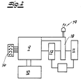
- a control device 9 is initially closed in FIG. 2 recognize which is designed as a microprocessor.
- the Microprocessor is programmed as an adjustable timer and the time intervals can be set by an operator a switch 16 can be set and changed.
- the Control device 9 has a power driver 17 connected, which the electrical signals of the control device 9 on to drive the electromotive Drive 8 suitable power levels amplified.
- the Power driver 17 is in turn via a warning device 18 connected to an electric motor 11.
- the warning device 18 is set up for measuring the current and activates an alarm device designed as a light-emitting diode 19 once the amperage reaches a given Threshold exceeded.
- the warning device 18 is as Part of the microprocessor trained and switches the Power supply to the electromotive drive 8 activated alarm device 19.
- the electromechanical Travel control a rotor 21 and a stator 22 as well has a pair of contacts 20.
- the rotor 21 is with the Drive shaft of the reduction gear or the motor shaft connected.
- the stator is fixed to the housing.
- the stator is as one forming the contact of the contact pair 20 Grinder 23 formed.
- the Rotor forms the other contact of the contact pair, whereby a circularly arranged contact track 24 with a non-conductive contact area 25 is set up.
- the non-conductive contact path region 25 forms an angular region A.
- the contact pair 20 is closed when the Grinder 23 moves outside the angular range A.
- the contact pair 20 is open when the Grinder 23 is within the angular range A.
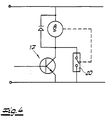
- 4 is a schematic of the circuit of the electromotive drive 8, the power driver 17 and of the contact pair 20 shown. The functionality results a detailed comparison of the 3 and 4 as follows: The contact pair is at rest 20 opened and the electromotive drive 8 de-energized. after a preselected time interval, the Power driver 17, which is designed as a switching transistor is an impulse. This impulse causes Start of the electric motor drive 8. The Grinder 23 out of the angular range A. Once the Grinder 23 has emerged from the angular range A, the contact pair 20 is closed. Therefore, the electromagnetic drive 8 regardless of the duration of current applied to the power driver 17. It it goes without saying that the one supplied to the power driver 17 Pulse must have a pulse duration that is sufficient to move the grinder 23 out of the angular range A.
- the Angular range A then corresponds to the length of the cam (or Cams) in the circumferential direction.
- the warning device 18 can also be easily connect to a central control system. Lubrication is also dependent on the machine running time possible.
- FIGS 5 and 6. It can be seen that here the housing 4 with the fitted adjusting piston 7 in a cylindrical Receiving chamber 26 is arranged eccentrically, which Housing 4 has a wall region B of the cylindrical receiving chamber 26 touches that in the floor plan next to the Housing 4 free crescent-shaped receiving chamber space 27 the electric motor drive 8 is arranged, the one Output pinion 28 has.
- the top is the Receiving chamber 26 arranged a gear chamber 29, the has at least one gear wheel 30. This works on the output pinion 28.
- the receiving chamber 26 is through a releasable cover assembly 31 closed in Embodiment consists of two lids, one of which is screwable. It is understood that the usual Seals are arranged.
- the electric motor drive 8 is the broadest Area of the crescent-shaped receiving chamber space 27, being on one side of the electromotive Drive 8, the electrical control device 9, on the on the other hand, the means 10 for the energy supply of the electromotive drive 8 are arranged.
- the housing 4 touches Control slot 32 is recessed, the housing 4th reveals.
- the described components of the cylindrical Receiving chamber 26 and cover 31 are off Injection molded plastic.
Landscapes
- Engineering & Computer Science (AREA)
- General Engineering & Computer Science (AREA)
- Mechanical Engineering (AREA)
- Connection Of Motors, Electrical Generators, Mechanical Devices, And The Like (AREA)
- Transmission Devices (AREA)
- Encapsulation Of And Coatings For Semiconductor Or Solid State Devices (AREA)
- Lubricants (AREA)
- Reciprocating Pumps (AREA)
- Lubrication Of Internal Combustion Engines (AREA)
- Coating Apparatus (AREA)
- Control Of Electric Motors In General (AREA)
Description
wobei der Leistungstreiber in vorgewählten Zeitintervallen einen Impuls erhält, der verstärkt wird und ein Anlaufen des elektromotorischen Antriebes bewirkt,
wobei beim Anlaufen des elektromotorischen Antriebes ein Stromkreis geschlossen wird und der elektromotorische Antrieb unabhängig von der Dauer des am Leistungstreiber anliegenden Impulses Strom erhält und
wobei der elektromotorische Antrieb so lange arbeitet, bis der Rotor eine vorgegebene Winkelstellung erreicht, in der das Kontaktpaar den Stromfluss zum elektromotorischen Antrieb unterbricht.
- Fig. 1
- einen Vertikalschnitt durch einen erfindungsgemäßen Schmierstoffgeber,
- Fig. 2
- ein Blockschaltbild der elektrischen Baugruppen für die Ausführungsform mit Elektromotor sowie Untersetzungsgetriebe,
- Fig. 3 a, b
- einen Vertikalschnitt durch eine elektromechanische Laufwegesteuerung (a) sowie eine Aufsicht auf den Rotor derselben (b),
- Fig. 4
- eine elektronische Schaltung für die Laufwegesteuerung gemäß Fig. 3.
- Fig. 5
- entsprechend der Fig. 1 eine andere Ausführungsform eines erfindungsgemäßen Schmierstoffspenders,
- Fig. 6
- einen Schnitt in Richtung A-A durch den Gegenstand der Fig. 5.
Claims (14)
- Schmierstoffspender zur Abgabe eines Schmierstoffes an eine Maschine mitwobei der elektromotorische Antrieb (8) als Getriebemotor mit einem Elektromotor (11) und mit einem Untersetzungsgetriebe (12) ausgebildet ist, wobei die Getriebeabtriebswelle (13) des Untersetzungsgetriebes über ein Schubgetriebe mit dem Stellkolben (7) verbunden ist und wobei die Steuerungsvorrichtung (9) einen Zeitgeber zur Ansteuerung des elektromotorischen Antriebes (8) in nach Maßgabe der einzurichtenden Schmierstoffrate vorbestimmbaren Zeitintervallen aufweist, dadurch gekennzeichnet, dass die Steuerungsvorrichtung (9) mit dem elektromotorischen Antrieb (8) über einen Leistungstreiber (17) verbunden ist, welcher die elektrischen Signale der Steuerungsvorrichtung (9) auf zum Antrieb des elektromotorischen Antriebes (8) geeignete Leistungspegel verstärkt, und dass eine elektromechanische Laufwegesteuerung vorgesehen ist, die einen drehfest mit einer Welle des Untersetzungsgetriebes verbundenen Rotor (21), einen gehäusefesten Stator (22) und ein in vorgegebenen Winkelstellungen des Rotors betätigbares Kontaktpaar (20) aufweist,Gehäuse (4) für die Aufnahme eines Schmierstoffvorrates,Maschinenanschlussteil (5) mit Schmierstoffabgabekanal (6) an einer Seite des Gehäuses (4),in das Gehäuse (4) eingepaßtem Stellkolben (7), dessen Bewegung, die Schmierstoffrate bestimmend, steuerbar ist,elektromotorischem Antrieb (8) zur Bewegung des Stellkolbens (7),einer mit dem elektromotorischen Antrieb verbundenen elektrischen Steuerungsvorrichtung (9) zur Steuerung der Schmierstoffrate undMittel (10) zur Versorgung des elektromotorischen Antriebes (8) und der elektrischen Steuerungsvorrichtung (9) mit elektrischer Energie,
wobei der Leistungstreiber (17) in vorgewählten Zeitintervallen einen Impuls erhält, der verstärkt wird und ein Anlaufen des elektromotorischen Antriebes (8) bewirkt,
wobei beim Anlaufen des elektromotorischen Antriebes (8) ein Stromkreis geschlossen wird und der elektromotorische Antrieb (8) unabhängig von der Dauer des am Leistungstreiber (17) anliegenden Impulses Strom erhält und
wobei der elektromotorische Antrieb (8) so lange arbeitet, bis der Rotor (21) eine vorgegebene Winkelstellung erreicht, in der das Kontaktpaar (20) den Stromfluss zum elektromotorischen Antrieb (8) unterbricht. - Schmierstoffspender nach Anspruch 1, dadurch gekennzeichnet, dass der Stator einen Schleifer (23) und der Rotor eine umlaufende Kontaktbahn (24) mit mindestens einem nicht leitenden Kontaktbahnbereich (25) aufweist.
- Schmierstoffspender nach Anspruch 1, dadurch gekennzeichnet, dass der Rotor (21) als Nockenscheibe mit zumindest einer Schaltnocke ausgebildet ist, und dass die Schalteinrichtung (20) einen Taster mit einem Betätigungselement aufweist, welches durch die Schaltnocke betätigbar ist.
- Schmierstoffspender nach einem der Ansprüche 1 bis 3, dadurch gekennzeichnet, dass das Schubgetriebe als Schraubengetriebe mit drehbarer Spindel (14) und an dem Stellkolben (7) drehfest befestigter oder in den Stellkolben (7) ausgeformter Spindelmutter (15) ausgebildet ist.
- Schmierstoffspender nach einem der Ansprüche 1 bis 4, dadurch gekennzeichnet, dass die Steuerungsvorrichtung (9) einen Mikroprozessor aufweist, dass der Mikroprozessor zumindest zum Teil als einstellbarer Zeitgeber programmiert ist, und dass die Zeitintervalle über von einer Bedienperson betätigbare Schalter (16) einstellbar und veränderbar sind.
- Schmierstoffspender nach einem der Ansprüche 1 bis 5, dadurch gekennzeichnet, dass die elektrische Steuerungsvorrichtung (9) eine Warnvorrichtung (18) aufweist, mittels welcher bei unzulässiger Stromaufnahme des elektromotorischen Antriebes (8) dessen Stromversorgung ausschaltbar und eine Alarmvorrichtung (19) aktivierbar ist.
- Schmierstoffspender nach einem der Ansprüche 1 bis 6, dadurch gekennzeichnet, dass der elektromotorische Antrieb (8), die Steuerungsvorrichtung (9) und/oder die Mittel (10) zur Versorgung mit elektrischer Energie lösbar mit dem Gehäuse (4) und mit dem Stellkolben (7) verbunden sind.
- Schmierstoffspender nach einem der Ansprüche 1 bis 7, dadurch gekennzeichnet, dass der elektromotorische Antrieb (8), die Steuerungsvorrichtung (9) und die Mittel (10) zur Versorgung mit elektrischer Energie auf der dem Schmierstoff (2) abgewandten Seite des Stellkolbens (7) in das Gehäuse (4) eingebaut sind.
- Schmierstoffspender nach einem der Ansprüche 1 bis 8, dadurch gekennzeichnet, dass das Gehäuse (4) mit dem eingepaßten Stellkolben (7) in einer zylindrischen Aufnahmekammer (26) exzentrisch angeordnet ist, wobei das Gehäuse (4) einen Wandbereich (B) der zylindrischen Aufnahmekammer (26) berührt, dass in dem im Grundriß neben dem Gehäuse (4) freibleibenden sichelförmigen Aufnahmekammerraum (27) der elektromotorische Antrieb (8) angeordnet ist, der ein Abtriebsritzel (28) aufweist, dass im Oberteil der Aufnahmekammer (26) ein Getrieberaum (29) angeordnet ist, der zumindest ein Getrieberad (30) aufweist, auf welches das Abtriebsritzel (28) arbeitet, und dass die Aufnahmekammer (26) durch eine lösbare Deckelanordnung (31) verschlossen ist.
- Schmierstoffspender nach Anspruch 9, dadurch gekennzeichnet, dass in den sichelförmigen Aufnahmekammerraum (27), vorzugsweise neben dem elektromotorischen Antrieb (8), auch die elektrische Steuervorrichtung (9) angeordnet ist.
- Schmierstoffspender nach Anspruch 9, dadurch gekennzeichnet, dass in dem sichelförmigen Aufnahmekammerraum (27), vorzugsweise neben dem elektromotorischen Antrieb (8), auch die Mittel (10) für die Versorgung des elektromotorischen Antriebs (8) mit elektrischer Energie angeordnet sind.
- Schmierstoffspender nach einem der Ansprüche 9 bis 11, dadurch gekennzeichnet, dass der elektromotorische Antrieb (8) im breitesten Bereich des sichelförmigen Aufnahmekammerraums (27) angeordnet ist und einerseits die elektrische Steuervorrichtung (9) für den elektromotorischen Antrieb (8) sowie andererseits die Mittel (10) für die Energieversorgung des elektromotorischen Antriebs (8) angeordnet sind.
- Schmierstoffspender nach einem der Ansprüche 1 bis 12, dadurch gekennzeichnet, dass in dem Wandbereich (8) der zylindrischen Aufnahmekammer (26), den das Gehäuse berührt, ein Kontrollschlitz (32) ausgespart ist, der das Gehäuse (4) erkennen läßt.
- Schmierstoffspender nach einem der Ansprüche 9 bis 13, dadurch gekennzeichnet, dass die zylindrische Aufnahmekammer (26) und der Deckel (31) aus Kunststoff gespritzt sind.
Priority Applications (10)
| Application Number | Priority Date | Filing Date | Title |
|---|---|---|---|
| DE4422407A DE4422407C2 (de) | 1994-06-29 | 1994-06-29 | Schmierstoffspender |
| NO954832A NO301909B1 (no) | 1994-06-29 | 1995-11-28 | Smöremiddelutdeler for avgivelse av et smöremiddel til en maskin |
| AT95118824T ATE215200T1 (de) | 1994-06-29 | 1995-11-30 | Schmierstoffspender mit elektromotorisch gesteuerter abgabe eines schmierstoffes an eine maschine |
| DE59510132T DE59510132D1 (de) | 1994-06-29 | 1995-11-30 | Schmierstoffspender mit elektromotorisch gesteuerter Abgabe eines Schmierstoffes an eine Maschine |
| EP95118824A EP0777077B1 (de) | 1994-06-29 | 1995-11-30 | Schmierstoffspender mit elektromotorisch gesteuerter Abgabe eines Schmierstoffes an eine Maschine |
| ES95118824T ES2172551T3 (es) | 1994-06-29 | 1995-11-30 | Dispensador de lubricante con aportacion de un lubricante a una maquina bajo control de motor electrico. |
| DE19544692A DE19544692A1 (de) | 1994-06-29 | 1995-11-30 | Schmierstoffspender mit elektromotorisch gesteuerter Abgabe eines Schmierstoffes an eine Maschine |
| AU39174/95A AU716725B2 (en) | 1994-06-29 | 1995-12-01 | Lubricant dispenser |
| US08/567,227 US5634531A (en) | 1994-06-29 | 1995-12-05 | Electrically powered automatic lubricant dispenser |
| JP7318832A JPH09178087A (ja) | 1994-06-29 | 1995-12-07 | 機械への電動機制御による潤滑材供給を行なう潤滑装置 |
Applications Claiming Priority (7)
| Application Number | Priority Date | Filing Date | Title |
|---|---|---|---|
| DE4422407A DE4422407C2 (de) | 1994-06-29 | 1994-06-29 | Schmierstoffspender |
| NO954832A NO301909B1 (no) | 1994-06-29 | 1995-11-28 | Smöremiddelutdeler for avgivelse av et smöremiddel til en maskin |
| EP95118824A EP0777077B1 (de) | 1994-06-29 | 1995-11-30 | Schmierstoffspender mit elektromotorisch gesteuerter Abgabe eines Schmierstoffes an eine Maschine |
| DE19544692A DE19544692A1 (de) | 1994-06-29 | 1995-11-30 | Schmierstoffspender mit elektromotorisch gesteuerter Abgabe eines Schmierstoffes an eine Maschine |
| AU39174/95A AU716725B2 (en) | 1994-06-29 | 1995-12-01 | Lubricant dispenser |
| US08/567,227 US5634531A (en) | 1994-06-29 | 1995-12-05 | Electrically powered automatic lubricant dispenser |
| JP7318832A JPH09178087A (ja) | 1994-06-29 | 1995-12-07 | 機械への電動機制御による潤滑材供給を行なう潤滑装置 |
Publications (2)
| Publication Number | Publication Date |
|---|---|
| EP0777077A1 EP0777077A1 (de) | 1997-06-04 |
| EP0777077B1 true EP0777077B1 (de) | 2002-03-27 |
Family
ID=27560567
Family Applications (1)
| Application Number | Title | Priority Date | Filing Date |
|---|---|---|---|
| EP95118824A Expired - Lifetime EP0777077B1 (de) | 1994-06-29 | 1995-11-30 | Schmierstoffspender mit elektromotorisch gesteuerter Abgabe eines Schmierstoffes an eine Maschine |
Country Status (8)
| Country | Link |
|---|---|
| US (1) | US5634531A (de) |
| EP (1) | EP0777077B1 (de) |
| JP (1) | JPH09178087A (de) |
| AT (1) | ATE215200T1 (de) |
| AU (1) | AU716725B2 (de) |
| DE (3) | DE4422407C2 (de) |
| ES (1) | ES2172551T3 (de) |
| NO (1) | NO301909B1 (de) |
Families Citing this family (68)
| Publication number | Priority date | Publication date | Assignee | Title |
|---|---|---|---|---|
| US6012551A (en) * | 1995-04-15 | 2000-01-11 | Gerhard Dohring | Apparatus for automatic lubricant delivery |
| CH692417A5 (de) * | 1996-10-16 | 2002-06-14 | Dreve Otoplastik Gmbh | Vorrichtung insbesondere zum Auspressen von Kunststoffmassen enthaltenden Kartuschen. |
| US5839335A (en) * | 1996-11-01 | 1998-11-24 | Tilley; Robert W. | Saw blade lubricating apparatus |
| DE19709680A1 (de) * | 1997-03-11 | 1998-09-17 | Satzinger Gmbh & Co | Schmierstoffgeber für rotierende Bauteile, insbesondere eine rotierende Hohlwelle |
| US5878842A (en) * | 1997-03-19 | 1999-03-09 | Trico Manufacturing Corporation | Volumetric lubricant dispensing apparatus and method of use for same |
| US7017712B1 (en) * | 1997-03-19 | 2006-03-28 | Trico Mfg. Corp. | Apparatus and method for lubricant condition control and monitoring |
| US6447573B1 (en) | 1997-03-19 | 2002-09-10 | Trico Manufacturing Company | Apparatus and method for lubricant condition control and monitoring |
| US6101968A (en) * | 1997-08-11 | 2000-08-15 | Innovative Injectors, Inc. | Power-assist cake decorator |
| EP0982528A1 (de) | 1998-08-22 | 2000-03-01 | De Limon Fluhme Gmbh | Schmierstoffgeber |
| EP0982527A1 (de) | 1998-08-22 | 2000-03-01 | De Limon Fluhme Gmbh | Schmierstoffgeber |
| US6022163A (en) * | 1998-11-13 | 2000-02-08 | Asfur; Amal | Gel dispensing hair brush |
| DE19857289C1 (de) * | 1998-12-13 | 2000-05-04 | Brueckner Maschbau | Verfahren zur Schmierung von Transportsystemen oder Teilen davon sowie Verwendung einer Schmiermittelvorrichtung zur Durchführung des Verfahrens und ein zugehöriges Transportsystem mit entsprechender Schmiermitteleinrichtung |
| DE29822967U1 (de) * | 1998-12-23 | 2000-05-11 | ESPE Dental AG, 82229 Seefeld | Gerät zum Ausbringen von fließfähigen Massen |
| KR20010001671A (ko) * | 1999-06-07 | 2001-01-05 | 조희남 | 이송용 스크류축의 회전을 이송 압입력으로 변환한 자동 구리스 |
| DE19947458A1 (de) | 1999-10-02 | 2001-05-31 | Perma Tec Gmbh & Co Kg | Verfahren zur Schmierung eines Wälzlagers |
| KR100282128B1 (ko) * | 1999-12-02 | 2001-02-15 | 양윤종 | 윤활유 자동 공급 장치 |
| KR100282129B1 (ko) * | 1999-12-02 | 2001-02-15 | 양윤종 | 마이컴을 이용한 윤활유 자동공급방법 |
| US6932856B2 (en) | 1999-12-08 | 2005-08-23 | Trico Mfg. Corp. | Apparatus and method for lubricant condition control and monitoring from a remote location |
| US6409121B1 (en) * | 2000-08-30 | 2002-06-25 | The Boeing Company | In flight autolubrication system for the mechanical members of aircraft landing gear |
| KR100382195B1 (ko) * | 2000-09-26 | 2003-05-09 | 송유철 | 윤활유 자동 주유장치 |
| EP1482237A1 (de) * | 2003-05-29 | 2004-12-01 | Solgras Industrial, S.L. | Schmiervorrichtung mit Patrone |
| AU2005240682B2 (en) * | 2004-05-06 | 2010-11-25 | Stephania Holdings Inc. | Automatic motor driven in-line piston pump lubricator |
| US7862875B2 (en) * | 2004-10-04 | 2011-01-04 | Trico Corporation | Flinger disc |
| US20060073303A1 (en) * | 2004-10-04 | 2006-04-06 | Trico Mfg. Corp. | Flinger disc |
| US20070045337A1 (en) * | 2005-06-24 | 2007-03-01 | Hornsby James R | Dispensing device |
| US20080041880A1 (en) * | 2006-06-05 | 2008-02-21 | Roger Babineau | Handheld foodstuff dispenser |
| MX2009008163A (es) * | 2007-02-02 | 2009-08-12 | Messier Dowty Inc | Ensamble de perno autolubricante. |
| USD589597S1 (en) | 2007-04-04 | 2009-03-31 | Trico Mfg. Corp | Flinger disc |
| DE202007016788U1 (de) | 2007-11-29 | 2008-02-21 | Lincoln Gmbh | Schmierstoffgeber |
| US20090173581A1 (en) * | 2007-12-18 | 2009-07-09 | Small Car Motors, Inc. | Air Tool Oil Apparatus |
| US8096164B2 (en) | 2008-01-17 | 2012-01-17 | Trico Corporation | Apparatus and methods for management of fluid condition |
| PL2250350T3 (pl) | 2008-02-08 | 2015-02-27 | Flashlube Pty Ltd | System doprowadzania środka smarnego do silników spalinowych wewnętrznego spalania |
| US8220671B2 (en) | 2008-03-12 | 2012-07-17 | Trico Corporation | Lubricant dispenser with nozzle |
| USD687923S1 (en) | 2008-06-03 | 2013-08-13 | Trico Corporation | Lubricant dispensing nozzle |
| US9151443B2 (en) | 2009-02-22 | 2015-10-06 | Stephania Holdings Inc. | Fluid holder and electromechanical lubricator employing same |
| US20100217446A1 (en) * | 2009-02-22 | 2010-08-26 | Orlitzky Stephan Karl | Fluid Holder And Electromechanical Lubricator Employing Same |
| DE102009022707B4 (de) * | 2009-03-05 | 2014-03-27 | Perma-Tec Gmbh & Co. Kg | Schmierstoffspender |
| US8147684B2 (en) * | 2009-03-27 | 2012-04-03 | Trico Corporation | Apparatus and methods for lubricant filtration and drum pump filtration system |
| US8147683B2 (en) | 2010-01-22 | 2012-04-03 | Trico Corporation | Portable lubricant filtration system and method |
| US20130020350A1 (en) * | 2010-09-01 | 2013-01-24 | Stainless Steel Coatings, Inc. | Method of dispensing pesticidal bait and electrically powered dispensing device |
| US9388940B2 (en) | 2010-11-29 | 2016-07-12 | Lincoln Industrial Corporation | Variable speed stepper motor driving a lubrication pump system |
| US8936135B2 (en) | 2010-11-29 | 2015-01-20 | Lincoln Industrial Corporation | Pump having heated reservoir |
| US9222618B2 (en) | 2010-11-29 | 2015-12-29 | Lincoln Industrial Corporation | Stepper motor driving a lubrication pump providing uninterrupted lubricant flow |
| DE202011051373U1 (de) * | 2011-09-20 | 2013-01-08 | Perma-Tec Gmbh & Co. Kg | Sammelbehälter für Schmierstoffe |
| EP2610513B1 (de) * | 2012-01-02 | 2014-08-13 | Aktiebolaget SKF | Anordnung zum Schmieren eines Lagers |
| DE102012100035B4 (de) * | 2012-01-03 | 2014-06-12 | Perma-Tec Gmbh & Co. Kg | Schmierstoffspender |
| USD687922S1 (en) | 2012-04-25 | 2013-08-13 | Trico Corporation | Lubricant dispenser |
| USD687921S1 (en) | 2012-04-25 | 2013-08-13 | Trico Corporation | Lubricant dispenser |
| USD696956S1 (en) | 2012-04-25 | 2014-01-07 | Trico Corporation | Lubricant dispenser |
| CN103075627B (zh) * | 2013-01-24 | 2015-05-20 | 福建省平潭县新万顺机电有限公司 | 电动桶用倒吸润滑脂泵 |
| US9671065B2 (en) | 2013-10-17 | 2017-06-06 | Lincoln Industrial Corporation | Pump having wear and wear rate detection |
| US20150114992A1 (en) * | 2013-10-31 | 2015-04-30 | Aktiebolaget Skf | Grease gun with sensing capability and variable speed |
| KR101546379B1 (ko) * | 2014-03-07 | 2015-08-21 | 주식회사 케이엘티 | 윤활유 주입기 |
| FR3055561B1 (fr) * | 2016-09-08 | 2021-01-15 | Aptar France Sas | Distributeur de produit fluide. |
| KR101903184B1 (ko) * | 2016-11-30 | 2018-10-01 | 주식회사 케이엘티 | 윤활유 주입 장치 |
| DE102017125307B4 (de) * | 2017-10-27 | 2025-12-24 | Groeneveld-Beka Gmbh | Zentralschmieranlage und System |
| GB201721065D0 (en) * | 2017-12-15 | 2018-01-31 | Ondosis Ab | Delivery device for drug pellets |
| US11512810B2 (en) * | 2019-10-04 | 2022-11-29 | Dodge Industrial, Inc. | Automatic lubricator for lubricating an object |
| US11499673B2 (en) * | 2019-10-04 | 2022-11-15 | Dodge Industrial, Inc. | Automatic lubricator for lubricating an object |
| KR102313669B1 (ko) * | 2020-07-17 | 2021-10-18 | 주식회사 케이엘티 | 고압 발생이 가능한 다중 윤활유 주입기 |
| CN112604906B (zh) * | 2020-12-25 | 2021-08-31 | 适新科技(苏州)有限公司 | 一种用于汽车电池基板的精密多通道结构胶点胶装置 |
| KR102609812B1 (ko) | 2021-10-08 | 2023-12-05 | 주식회사 케이엘티 | 윤활유 주입기 |
| KR102658338B1 (ko) * | 2021-11-09 | 2024-04-17 | 주식회사 아원 | 복합기능 그리스 레벨 팔로우형 전기식 그리스 베럴 펌프 및 그 배관구조 |
| DE102021129977B4 (de) | 2021-11-17 | 2025-12-04 | Perma-Tec Gmbh & Co. Kg | Schmierstoffspender |
| DE102023105820B3 (de) | 2023-03-09 | 2024-05-29 | Perma-Tec Gmbh & Co. Kg | Verfahren zur Bestimmung und/oder Überwachung des Zustandes eines Schmierstoffspenders |
| KR102642938B1 (ko) * | 2023-10-10 | 2024-02-29 | 최성찬 | 베어링 및 기어의 수명 개선을 위한 스마트 윤활 시스템 |
| EP4616964A1 (de) | 2024-03-13 | 2025-09-17 | JOST-Werke Deutschland GmbH | Vorrichtung zum betätigen einer kartusche |
| DE102024116438A1 (de) * | 2024-06-12 | 2025-12-18 | Jost-Werke Deutschland Gmbh | System mit einer Kartusche und einer Betätigungsvorrichtung |
Family Cites Families (15)
| Publication number | Priority date | Publication date | Assignee | Title |
|---|---|---|---|---|
| GB215205A (en) * | 1923-05-28 | 1924-05-08 | Ralph Redman Mcclure | Improvements in electrically operated oil cups |
| US3561565A (en) * | 1969-09-15 | 1971-02-09 | Dennis Frederick Woor | Pulse-actuated lubrication system |
| US4089624A (en) * | 1976-06-04 | 1978-05-16 | Becton, Dickinson And Company | Controlled pumping system |
| US4260076A (en) * | 1979-09-14 | 1981-04-07 | Whirlco, Inc. | Powered dispenser for caulking cartridge contents |
| NL8601666A (nl) * | 1986-06-25 | 1988-01-18 | Skf Ind Trading & Dev | Smeerinrichting. |
| US4770613A (en) * | 1987-08-20 | 1988-09-13 | Hoover Steven J | Apparatus for dispensing viscous lubricant |
| DE3818256A1 (de) * | 1988-05-28 | 1989-11-30 | Baier & Koeppel | Verfahren zur einstellung der schmierzeit einer schmiermittelpumpe und einrichtung zur durchfuehrung des verfahrens |
| JPH0429061A (ja) * | 1990-05-25 | 1992-01-31 | Meidensha Corp | 分注装置 |
| KR920002899A (ko) * | 1990-07-06 | 1992-02-28 | 야마무라 가쯔미 | 방출장치 |
| EP0558445A1 (de) * | 1992-02-20 | 1993-09-01 | Ciba-Geigy Ag | Sulfonylharnstoffe als Herbizide |
| DE4209776A1 (de) | 1992-03-26 | 1993-09-30 | Satzinger Gmbh & Co | Schmierstoffspender zur gasgesteuerten Abgabe eines Schmiermittels an eine Maschine |
| DE4214827A1 (de) * | 1992-05-10 | 1993-11-11 | Eric Van Damme | Vorrichtung zum dosierten Zuführen von flüssigen oder viskosen Substanzen an eine Verbrauchsstelle |
| GB2271391B (en) * | 1992-10-12 | 1995-08-02 | Hornche Trading Co Ltd | Automatic grease dispenser |
| DE9214096U1 (de) * | 1992-10-19 | 1992-12-17 | Hornche Trading Co., Ltd., Taoyuan, Taoyuan | Automatischer Schmiermittelspender |
| DE9309575U1 (de) * | 1993-06-29 | 1993-10-07 | Kozlowski, Edmund, 22399 Hamburg | Selbsttätig Schmierstoff oder andere Medien abgebendes bzw. zum Dosieren geeignetes elektromechanisch angetriebenes Gerät |
-
1994
- 1994-06-29 DE DE4422407A patent/DE4422407C2/de not_active Expired - Fee Related
-
1995
- 1995-11-28 NO NO954832A patent/NO301909B1/no not_active IP Right Cessation
- 1995-11-30 DE DE59510132T patent/DE59510132D1/de not_active Expired - Fee Related
- 1995-11-30 ES ES95118824T patent/ES2172551T3/es not_active Expired - Lifetime
- 1995-11-30 DE DE19544692A patent/DE19544692A1/de not_active Withdrawn
- 1995-11-30 AT AT95118824T patent/ATE215200T1/de not_active IP Right Cessation
- 1995-11-30 EP EP95118824A patent/EP0777077B1/de not_active Expired - Lifetime
- 1995-12-01 AU AU39174/95A patent/AU716725B2/en not_active Ceased
- 1995-12-05 US US08/567,227 patent/US5634531A/en not_active Expired - Fee Related
- 1995-12-07 JP JP7318832A patent/JPH09178087A/ja active Pending
Also Published As
| Publication number | Publication date |
|---|---|
| US5634531A (en) | 1997-06-03 |
| DE59510132D1 (de) | 2002-05-02 |
| NO954832D0 (no) | 1995-11-28 |
| DE4422407C2 (de) | 2001-07-05 |
| AU716725B2 (en) | 2000-03-02 |
| NO954832L (no) | 1997-05-29 |
| AU3917495A (en) | 1997-06-05 |
| DE4422407A1 (de) | 1996-01-04 |
| DE19544692A1 (de) | 1997-06-05 |
| JPH09178087A (ja) | 1997-07-11 |
| ES2172551T3 (es) | 2002-10-01 |
| ATE215200T1 (de) | 2002-04-15 |
| EP0777077A1 (de) | 1997-06-04 |
| NO301909B1 (no) | 1997-12-22 |
Similar Documents
| Publication | Publication Date | Title |
|---|---|---|
| DE4422407C2 (de) | Schmierstoffspender | |
| DE3730448C2 (de) | ||
| EP1558474B1 (de) | Vorrichtung zum sperren der lenkspindel eines kraftfahrzeugs | |
| EP0826128B2 (de) | Einrichtung zur automatischen schmierstoffabgabe | |
| DE2039862B2 (de) | Automatisch wirkende Aerosolabgabevorrichtung | |
| EP0312781A1 (de) | Berührungslos gesteuerte Sanitärarmatur | |
| EP1873800A1 (de) | Elektrische Werkzeugmaschine und Schalter hierfür | |
| DE2731102B2 (de) | Pipettiergerät | |
| DE68916951T2 (de) | Vom motor gesteuerter schaltmechanismus. | |
| EP0845631A1 (de) | Schmierstoffspender | |
| DE2920789C2 (de) | Scheibenwisch- und Waschanlage für ein Kraftfahrzeug | |
| DE69312889T2 (de) | Vorrichtung zur Steuerung der Position eines Türspiegels bis zu einer vorbestimmten Position | |
| DE102005016259A1 (de) | Schmierstoffspender | |
| DE9422208U1 (de) | Schmierstoffspender mit elektromotorisch gesteuerter Abgabe eines Schmierstoffes an eine Maschine | |
| DE7827035U1 (de) | Schiebeschalter | |
| DE1184659B (de) | Elektrisch gesteuerte Zentralschmiereinrichtung fuer Kraftfahrzeuge od. dgl. | |
| DE3014827C2 (de) | Motorantrieb für Niederspannungs-Schutzschalter | |
| DE3523547A1 (de) | Stelleinrichtung, insbesondere zur tuerverriegelung bei kraftfahrzeugen | |
| DE102005028813A1 (de) | Antrieb für eine Scheibenwischanlage eines Fahrzeugs | |
| DE20320332U1 (de) | Elektronischer Fluidspender | |
| EP3866655B1 (de) | Fluidspender | |
| DE1490018C (de) | Programmschalter | |
| DE2546704A1 (de) | Zentrale schmiervorrichtung | |
| DE3503783A1 (de) | Ventilsteuerung fuer duschen | |
| DE1455941B2 (de) | Elektrischer Zug-Schub-Schalter zum Steuern von Scheibenwisch- und -Waschanlagen, insbesondere von Kraftfahrzeugen |
Legal Events
| Date | Code | Title | Description |
|---|---|---|---|
| PUAI | Public reference made under article 153(3) epc to a published international application that has entered the european phase |
Free format text: ORIGINAL CODE: 0009012 |
|
| AK | Designated contracting states |
Kind code of ref document: A1 Designated state(s): AT BE CH DE DK ES FR GB IT LI LU NL SE |
|
| 17P | Request for examination filed |
Effective date: 19970903 |
|
| RAP1 | Party data changed (applicant data changed or rights of an application transferred) |
Owner name: PERMA-TEC GMBH & CO. KG |
|
| 17Q | First examination report despatched |
Effective date: 19991001 |
|
| GRAG | Despatch of communication of intention to grant |
Free format text: ORIGINAL CODE: EPIDOS AGRA |
|
| GRAG | Despatch of communication of intention to grant |
Free format text: ORIGINAL CODE: EPIDOS AGRA |
|
| GRAH | Despatch of communication of intention to grant a patent |
Free format text: ORIGINAL CODE: EPIDOS IGRA |
|
| GRAH | Despatch of communication of intention to grant a patent |
Free format text: ORIGINAL CODE: EPIDOS IGRA |
|
| REG | Reference to a national code |
Ref country code: GB Ref legal event code: IF02 |
|
| GRAA | (expected) grant |
Free format text: ORIGINAL CODE: 0009210 |
|
| AK | Designated contracting states |
Kind code of ref document: B1 Designated state(s): AT BE CH DE DK ES FR GB IT LI LU NL SE |
|
| REF | Corresponds to: |
Ref document number: 215200 Country of ref document: AT Date of ref document: 20020415 Kind code of ref document: T |
|
| REG | Reference to a national code |
Ref country code: CH Ref legal event code: EP |
|
| REG | Reference to a national code |
Ref country code: CH Ref legal event code: NV Representative=s name: KELLER & PARTNER PATENTANWAELTE AG |
|
| REF | Corresponds to: |
Ref document number: 59510132 Country of ref document: DE Date of ref document: 20020502 |
|
| PG25 | Lapsed in a contracting state [announced via postgrant information from national office to epo] |
Ref country code: SE Free format text: LAPSE BECAUSE OF FAILURE TO SUBMIT A TRANSLATION OF THE DESCRIPTION OR TO PAY THE FEE WITHIN THE PRESCRIBED TIME-LIMIT Effective date: 20020627 Ref country code: DK Free format text: LAPSE BECAUSE OF FAILURE TO SUBMIT A TRANSLATION OF THE DESCRIPTION OR TO PAY THE FEE WITHIN THE PRESCRIBED TIME-LIMIT Effective date: 20020627 |
|
| ET | Fr: translation filed | ||
| REG | Reference to a national code |
Ref country code: ES Ref legal event code: FG2A Ref document number: 2172551 Country of ref document: ES Kind code of ref document: T3 |
|
| PG25 | Lapsed in a contracting state [announced via postgrant information from national office to epo] |
Ref country code: LU Free format text: LAPSE BECAUSE OF NON-PAYMENT OF DUE FEES Effective date: 20021130 Ref country code: AT Free format text: LAPSE BECAUSE OF NON-PAYMENT OF DUE FEES Effective date: 20021130 |
|
| PLBE | No opposition filed within time limit |
Free format text: ORIGINAL CODE: 0009261 |
|
| STAA | Information on the status of an ep patent application or granted ep patent |
Free format text: STATUS: NO OPPOSITION FILED WITHIN TIME LIMIT |
|
| 26N | No opposition filed |
Effective date: 20021230 |
|
| PGFP | Annual fee paid to national office [announced via postgrant information from national office to epo] |
Ref country code: DE Payment date: 20041105 Year of fee payment: 10 |
|
| PGFP | Annual fee paid to national office [announced via postgrant information from national office to epo] |
Ref country code: NL Payment date: 20041117 Year of fee payment: 10 |
|
| PGFP | Annual fee paid to national office [announced via postgrant information from national office to epo] |
Ref country code: CH Payment date: 20041119 Year of fee payment: 10 |
|
| PGFP | Annual fee paid to national office [announced via postgrant information from national office to epo] |
Ref country code: GB Payment date: 20041122 Year of fee payment: 10 |
|
| PGFP | Annual fee paid to national office [announced via postgrant information from national office to epo] |
Ref country code: FR Payment date: 20041123 Year of fee payment: 10 |
|
| PGFP | Annual fee paid to national office [announced via postgrant information from national office to epo] |
Ref country code: BE Payment date: 20041201 Year of fee payment: 10 |
|
| PGFP | Annual fee paid to national office [announced via postgrant information from national office to epo] |
Ref country code: ES Payment date: 20041215 Year of fee payment: 10 |
|
| PG25 | Lapsed in a contracting state [announced via postgrant information from national office to epo] |
Ref country code: LI Free format text: LAPSE BECAUSE OF NON-PAYMENT OF DUE FEES Effective date: 20051130 Ref country code: IT Free format text: LAPSE BECAUSE OF NON-PAYMENT OF DUE FEES;WARNING: LAPSES OF ITALIAN PATENTS WITH EFFECTIVE DATE BEFORE 2007 MAY HAVE OCCURRED AT ANY TIME BEFORE 2007. THE CORRECT EFFECTIVE DATE MAY BE DIFFERENT FROM THE ONE RECORDED. Effective date: 20051130 Ref country code: GB Free format text: LAPSE BECAUSE OF NON-PAYMENT OF DUE FEES Effective date: 20051130 Ref country code: CH Free format text: LAPSE BECAUSE OF NON-PAYMENT OF DUE FEES Effective date: 20051130 Ref country code: BE Free format text: LAPSE BECAUSE OF NON-PAYMENT OF DUE FEES Effective date: 20051130 |
|
| PG25 | Lapsed in a contracting state [announced via postgrant information from national office to epo] |
Ref country code: ES Free format text: LAPSE BECAUSE OF NON-PAYMENT OF DUE FEES Effective date: 20051201 |
|
| PG25 | Lapsed in a contracting state [announced via postgrant information from national office to epo] |
Ref country code: NL Free format text: LAPSE BECAUSE OF NON-PAYMENT OF DUE FEES Effective date: 20060601 Ref country code: DE Free format text: LAPSE BECAUSE OF NON-PAYMENT OF DUE FEES Effective date: 20060601 |
|
| REG | Reference to a national code |
Ref country code: CH Ref legal event code: PL |
|
| GBPC | Gb: european patent ceased through non-payment of renewal fee |
Effective date: 20051130 |
|
| PG25 | Lapsed in a contracting state [announced via postgrant information from national office to epo] |
Ref country code: FR Free format text: LAPSE BECAUSE OF NON-PAYMENT OF DUE FEES Effective date: 20060731 |
|
| NLV4 | Nl: lapsed or anulled due to non-payment of the annual fee |
Effective date: 20060601 |
|
| REG | Reference to a national code |
Ref country code: FR Ref legal event code: ST Effective date: 20060731 |
|
| REG | Reference to a national code |
Ref country code: ES Ref legal event code: FD2A Effective date: 20051201 |
|
| BERE | Be: lapsed |
Owner name: *PERMA-TEC G.M.B.H. & CO. K.G. Effective date: 20051130 |