EP0776626B1 - Sauggerät - Google Patents
Sauggerät Download PDFInfo
- Publication number
- EP0776626B1 EP0776626B1 EP96112987A EP96112987A EP0776626B1 EP 0776626 B1 EP0776626 B1 EP 0776626B1 EP 96112987 A EP96112987 A EP 96112987A EP 96112987 A EP96112987 A EP 96112987A EP 0776626 B1 EP0776626 B1 EP 0776626B1
- Authority
- EP
- European Patent Office
- Prior art keywords
- wet
- suction device
- magnet
- dry suction
- float
- Prior art date
- Legal status (The legal status is an assumption and is not a legal conclusion. Google has not performed a legal analysis and makes no representation as to the accuracy of the status listed.)
- Expired - Lifetime
Links
- 238000006073 displacement reaction Methods 0.000 claims abstract description 9
- 239000012528 membrane Substances 0.000 claims description 29
- 230000005291 magnetic effect Effects 0.000 description 9
- 239000007788 liquid Substances 0.000 description 8
- 238000010276 construction Methods 0.000 description 2
- 238000001816 cooling Methods 0.000 description 2
- 239000000463 material Substances 0.000 description 2
- 239000002245 particle Substances 0.000 description 2
- 230000005540 biological transmission Effects 0.000 description 1
- 238000006243 chemical reaction Methods 0.000 description 1
- 230000001419 dependent effect Effects 0.000 description 1
- 238000007598 dipping method Methods 0.000 description 1
- 239000004744 fabric Substances 0.000 description 1
- 239000006260 foam Substances 0.000 description 1
- 239000004816 latex Substances 0.000 description 1
- 229920000126 latex Polymers 0.000 description 1
- 238000007789 sealing Methods 0.000 description 1
- 230000001960 triggered effect Effects 0.000 description 1
- XLYOFNOQVPJJNP-UHFFFAOYSA-N water Substances O XLYOFNOQVPJJNP-UHFFFAOYSA-N 0.000 description 1
Images

Classifications
-
- A—HUMAN NECESSITIES
- A47—FURNITURE; DOMESTIC ARTICLES OR APPLIANCES; COFFEE MILLS; SPICE MILLS; SUCTION CLEANERS IN GENERAL
- A47L—DOMESTIC WASHING OR CLEANING; SUCTION CLEANERS IN GENERAL
- A47L7/00—Suction cleaners adapted for additional purposes; Tables with suction openings for cleaning purposes; Containers for cleaning articles by suction; Suction cleaners adapted to cleaning of brushes; Suction cleaners adapted to taking-up liquids
- A47L7/0004—Suction cleaners adapted to take up liquids, e.g. wet or dry vacuum cleaners
- A47L7/0023—Recovery tanks
- A47L7/0028—Security means, e.g. float valves or level switches for preventing overflow
-
- A—HUMAN NECESSITIES
- A47—FURNITURE; DOMESTIC ARTICLES OR APPLIANCES; COFFEE MILLS; SPICE MILLS; SUCTION CLEANERS IN GENERAL
- A47L—DOMESTIC WASHING OR CLEANING; SUCTION CLEANERS IN GENERAL
- A47L7/00—Suction cleaners adapted for additional purposes; Tables with suction openings for cleaning purposes; Containers for cleaning articles by suction; Suction cleaners adapted to cleaning of brushes; Suction cleaners adapted to taking-up liquids
- A47L7/0004—Suction cleaners adapted to take up liquids, e.g. wet or dry vacuum cleaners
- A47L7/0023—Recovery tanks
- A47L7/0038—Recovery tanks with means for emptying the tanks
Definitions
- the invention relates to a wet and dry vacuum cleaner Collection container, into which an intake line opens, with a negative pressure in the collecting container generating suction unit and with one in the collection container arranged, depending on the height actuating a switch Swimmer.
- Such a wet-dry vacuum cleaner is for example in U.S. Patent 3,048,875.
- the swimmer actuates switches in the wall of the collecting container are inserted and into the interior of the collecting container protrude. These switches control the Water supply and the emptying of the well-known collection container.
- No. 4,404,441 A is a liquid container per se with a sump pump and a delivery line for known liquid pumped by this sump pump, one of the liquid level in the liquid container dependent, magnet-operated switch provided is, this switch will only be each other attracting poles that use magnets, act as well it with this liquid delivery device, u a Device completely by a wet and dry vacuum cleaner is different.
- Switching devices in which the magnetic effect is used are also known from US 4,865,073 A, in the frame a cooling system is described in this document, also an arrangement by a wet and dry vacuum cleaner is completely different.
- this previously known cooling system are in a switching device Magnets moved past each other so that they temporarily meet with Poles of the same name, at times but also with those of the same name, which should make different Switching movements with different Positions of a swimmer are generated.
- the actuator of the switch lever that can be pivoted about a fixed axis of rotation, which carries the second magnet at its free end.
- the lever on a microswitch be pivoted.
- a further preferred embodiment carries the float an extension that led into one Guide sleeve arranged vertically on the collecting container immersed and held at the upper end of the first magnet is.
- This extension leads simultaneously and connects the float along its displacement path him with the magnet.
- the guide sleeve is preferably on its upper side completed. According to a preferred further training the invention in an upper end wall of the Collection container can be arranged.
- Extension has a cross-shaped cross section and with their outer longitudinal edges on the inner wall the guide sleeve rests. This results in a perfect guidance and also a low mass for the extension.
- the float, the first magnet and possibly connecting the float with the first magnet Parts in one compared to the interior of the Collection container arranged subspace are and that the subspace at its lower end and over part of its adjoining height the interior of the collecting container by means of a flexible membrane is separated.
- the recording in one separate sub-area leads to the float and all moving parts including the first magnet not in contact with the groupage of the collection container come and therefore not get dirty can. Nevertheless, the level of the groupage in the Collection container through the flexible membrane the float and lifts it up when a certain one Degree of filling is reached.
- the configuration described with a partial space closed by a membrane can not only be used if the first magnet and the second magnet of the switch Poles of the same name face each other, but also with switches with magnets with unequal poles face each other, so get dressed. at such switches are, for example, by a spring, which separates the two magnets, the attraction counteracted. When the magnets come closer the magnetic attraction becomes so strong that the Spring force can be overcome, this becomes a Movement and actuation of the switch triggered. Also such a configuration should therefore be included, if the construction described above with a part of the room closed by a membrane becomes.
- the flexible membrane is not or only very little stretchable. This leaves avoid that in the event of an evacuation of the collection container the flexible membrane widens like a balloon.
- the flexible membrane can be made from one consist of relatively thick latex or of a flexible Material with a fabric insert that prevents expansion, but which is still flexible enough to float of the float on the product.
- the membrane Form a float at the bottom and at the bottom Has side surfaces surrounding the bag.
- the flexible The upper edge of the membrane is held against a wall that surrounds the upper portion of the subspace.
- the cage can be cylindrical, open at the bottom Wall.
- the cage on one of the top section the wall forming part of the room is attached and that between this wall and the cage the top of the flexible membrane is clamped. It can be done in the simplest Way the subspace be completed. It the flexible membrane on the top wall is sufficient postpone and then put over the cage that then fixes the membrane on the top wall and this protectively surrounds.
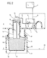
- the wet and dry vacuum cleaner shown only partially in the drawing has a collection container in the an intake pipe opens, with the dirt particles, Liquids etc. can be sucked in.
- the purpose of the collection container is still with a Suction unit in connection, the one in the collection container Negative pressure generated.
- this suction device corresponds known constructions and is therefore in the Drawing not shown.
- the Via a line 6 one only schematically in the drawing shown motor 7 of the suction unit on or off.
- the microswitch 5 could also operate a warning display, for example a warning lamp or an acoustic one Warning signal.
- a pivot lever 8 is pivotable on the microswitch 5 stored on a switching lug 9 of the microswitch 5 is present and when pivoting the switching lug 9 more or less in the microswitch 5 so that thereby the microswitch 5 in different switching positions arrives.
- the pivot lever 8 carries on his free end of a permanent magnet 10, which magnetizes so is that the two magnetic poles on its bottom and its top face each other, in the drawing is the magnetic north pole of this permanent magnet 10 indicated on its underside.
- the free end of the pivot lever 8 with the permanent magnet 10 is above a cylindrical guide sleeve 11 arranged the upper wall 1 of the collecting container interspersed and up over this top wall 1 protrudes.
- the guide sleeve closed at the top 11 projects down over the top wall 1 in the interior of the collecting container and is on the Bottom open.
- An extension 12 dips into the guide sleeve 11 one that protrudes from the guide sleeve 11 End connected to a float 13, for example a foam body.
- the extension 12 is cross-shaped, exists essentially consisting of two crossing plates, the with their longitudinal edges 14 on the inside of the guide sleeve 11 and thus the extension 12 guide in the guide sleeve 11 longitudinally.
- the extension 12 carries a permanent magnet 15, which magnetizes like the permanent magnet 10 is that the magnetic poles on the top and bottom face each other. In this case however, the north pole points up and the south pole points below, so that the two permanent magnets 10 and 15 face each other with magnetic poles of the same name. Cut they are only through the upper end wall 16 of the Guide sleeve 11.
- the guide sleeve 11 is inside the collecting container at a distance surrounded by one down from the top wall 1 projecting circular cylindrical wall 17, pushed onto a bag-shaped flexible membrane 18 is.
- the wall 17 and the membrane 18 form one Partial space closed off from the interior 2 19, which opens into the guide sleeve 11 and the float 13 and part of the extension 12 records.
- the subspace 19 can be completely closed, it is also possible, as shown in the drawing is, the subspace 19 via an opening 24 with the interior 2 and / or via an opening 25 with the Connect outside space 3. It is sufficient if this Openings 24, 25 have a very small diameter, for example between 2 and 3 mm. These openings serve as pressure equalization openings, at the same time is prevented due to the very small cross-section, that strong suction pressure losses occur through these openings.
- a cage 20 is pushed over the membrane 18, which in the essentially with a circular cylindrical sleeve 21 there is an inwardly curved edge 22. That edge 22 sits in a clamp on the lower edge of wall 17 on and clamps between itself and this wall 17 den top of the flexible membrane 18 a.
- the cage 20 surrounds the subspace 19 in the area of the flexible membrane 18 and extends down to at least the bottom Edge of subspace 19.
Landscapes
- Cookers (AREA)
- Load-Engaging Elements For Cranes (AREA)
- Manipulator (AREA)
- Branching, Merging, And Special Transfer Between Conveyors (AREA)
- Massaging Devices (AREA)
- Hooks, Suction Cups, And Attachment By Adhesive Means (AREA)
- Details Of Rigid Or Semi-Rigid Containers (AREA)
- External Artificial Organs (AREA)
Description
- Figur 1:
- eine Längsschnittansicht des oberen Teils eines Sammelbehälters eines Naß-Trocken-Saugers im Bereich eines den Schwimmer aufnehmenden Teilraums bei niedrigem Füllstand und
- Figur 2:
- eine Ansicht ähnlich Figur 1 bei hohem Füllstand.
Claims (17)
- Naß-Trocken-Sauger mit einem Sammelbehälter, in den eine Einsaugleitung einmündet, mit einem in dem Sammelbehälter einen Unterdruck erzeugenden Saugaggregat und mit einem im Sammelbehälter angeordneten, höhenabhängig einen Schalter betätigenden Schwimmer, dadurch gekennzeichnet, daß der Schwimmer (13) mit einem ersten Magneten (15) direkt oder indirekt verbunden ist, daß eine Hebe- und Senkbewegung des Schwimmers (13) zu einer Verschiebung dieses ersten Magneten (15) längs eines Verschiebewegs führt, daß dem ersten Magneten (15) ein zweiter Magnet (10) gleichpolig gegenüberstehend zugeordnet ist, der in Richtung des Verschiebewegs des ersten Magneten (15) verschieblich ist und mit einem Betätigungsglied (8) des Schalters (5) direkt oder indirekt verbunden ist.
- Naß-Trocken-Sauger nach Anspruch 1, dadurch gekennzeichnet, daß zwischen den beiden Magneten (10, 15) eine Wand (16) des Sammelbehälters angeordnet ist.
- Naß-Trocken-Sauger nach einem der voranstehenden Ansprüche, dadurch gekennzeichnet, daß das Betätigungsglied (8) ein um eine gerätefeste Drehachse schwenkbarer Hebel ist, der an seinem freien Ende den zweiten Magneten (10) trägt.
- Naß-Trocken-Sauger nach Anspruch 3, dadurch gekennzeichnet, daß der Hebel an einem Mikroschalter (5) schwenkbar gelagert ist.
- Naß-Trocken-Sauger nach einem der voranstehenden Ansprüche, dadurch gekennzeichnet, daß der Schwimmer (13) eine Verlängerung (12) trägt, die geführt in eine senkrecht am Sammelbehälter angeordnete Führungshülse (11) eintaucht und an deren oberem Ende der erste Magnet (15) gehalten ist.
- Naß-Trocken-Sauger nach Anspruch 5, dadurch gekennzeichnet, daß die Führungshülse (11) an ihrer Oberseite abgeschlossen ist.
- Naß-Trocken-Sauger nach Anspruch 5 oder 6, dadurch gekennzeichnet, daß die Führungshülse (11) in einer oberen Abschlußwand (1) des Sammelbehälters angeordnet ist.
- Naß-Trocken-Sauger nach einem der Ansprüche 5 bis 7, dadurch gekennzeichnet, daß die Verlängerung (12) einen kreuzförmigen Querschnitt aufweist und mit ihren außenliegenden Längskanten (14) an der Innenwand der Führungshülse (11) anliegt.
- Naß-Trocken-Sauger nach einem der voranstehenden Ansprüche, dadurch gekennzeichnet, daß der erste Schwimmer (13), der erste Magnet (15) und gegebenenfalls den Schwimmer (13) mit dem ersten Magneten (15) verbindende Teile (12) in einem gegenüber dem Innenraum (2) des Sammelbehälters abgeschlossenen Teilraum (19) angeordnet sind und daß der Teilraum (19) an seinem unteren Ende und über einen Teil seiner daran anschließenden Höhe gegenüber dem Innenraum (2) des Sammelbehälters mittels einer flexiblen Membran (18) abgetrennt ist.
- Naß-Trocken-Sauger nach Anspruch 9, dadurch gekennzeichnet, daß die flexible Membran (18) nicht oder nur sehr wenig dehnbar ist.
- Naß-Trocken-Sauger nach Anspruch 9 oder 10, dadurch gekennzeichnet, daß die flexible Membran (18) die Form eines den Schwimmer (13) an der Unterseite und an den Seitenflächen umgebenden Beutels hat.
- Naß-Trocken-Sauger nach einem der Ansprüche 9 bis 11, dadurch gekennzeichnet, daß die flexible Membran (18) mit ihrem oberen Rand an einer Wand (17) gehalten ist, die den oberen Abschnitt des Teilraums (19) umgibt.
- Naß-Trocken-Sauger nach einem der Ansprüche 9 bis 12, dadurch gekennzeichnet, daß der durch die flexible Membran (18) gebildete Bereich des Teilraums (19) von einem zum Sammelbehälter hin offenen Käfig (20) umgeben ist.
- Naß-Trocken-Sauger nach Anspruch 13, dadurch gekennzeichnet, daß der Käfig (20) eine nach unten hin offene, zylindrische Wand (21) umfaßt.
- Naß-Trocken-Sauger nach Anspruch 13 oder 14, dadurch gekennzeichnet, daß der Käfig (20) auf eine den oberen Abschnitt des Teilraums (19) bildende Wand (17) aufgesteckt ist und daß zwischen dieser Wand (17) und dem Käfig (20) der obere Rand der flexiblen Membran (18) eingeklemmt ist.
- Naß-Trocken-Sauger nach einem der Ansprüche 9 bis 15, dadurch gekennzeichnet, daß der Teilraum (19) über eine Öffnung (24) mit dem Innenraum (2) in Verbindung steht.
- Naß-Trocken-Sauger nach einem der Ansprüche 9 bis 16, dadurch gekennzeichnet, daß der Teilraum (19) über eine Öffnung (25) mit dem Außenraum (3) in Verbindung steht.
Applications Claiming Priority (2)
| Application Number | Priority Date | Filing Date | Title |
|---|---|---|---|
| DE19544773 | 1995-11-30 | ||
| DE19544773A DE19544773C1 (de) | 1995-11-30 | 1995-11-30 | Sauggerät |
Publications (3)
| Publication Number | Publication Date |
|---|---|
| EP0776626A2 EP0776626A2 (de) | 1997-06-04 |
| EP0776626A3 EP0776626A3 (de) | 1998-07-01 |
| EP0776626B1 true EP0776626B1 (de) | 2002-01-23 |
Family
ID=7778887
Family Applications (1)
| Application Number | Title | Priority Date | Filing Date |
|---|---|---|---|
| EP96112987A Expired - Lifetime EP0776626B1 (de) | 1995-11-30 | 1996-08-13 | Sauggerät |
Country Status (4)
| Country | Link |
|---|---|
| EP (1) | EP0776626B1 (de) |
| AT (1) | ATE212205T1 (de) |
| DE (1) | DE19544773C1 (de) |
| DK (1) | DK0776626T3 (de) |
Families Citing this family (3)
| Publication number | Priority date | Publication date | Assignee | Title |
|---|---|---|---|---|
| WO2001056447A2 (en) * | 2000-02-01 | 2001-08-09 | Conti Elektrikli Ev Aletleri Sanayi Ve Ticaret A.S. | Wet and dry horizontal vacuum cleaner |
| DE10240804B4 (de) * | 2002-08-30 | 2012-04-19 | Oase Gmbh | Schlammsauger |
| NL2001502C2 (nl) * | 2008-04-21 | 2009-10-22 | A A C Reerink Holding B V | Inrichting voor het opzuigen van vast vuil en vloeistof. |
Family Cites Families (4)
| Publication number | Priority date | Publication date | Assignee | Title |
|---|---|---|---|---|
| US3048875A (en) * | 1960-06-02 | 1962-08-14 | Joseph P Rossi | Pneumatic systems |
| US4404441A (en) * | 1980-09-09 | 1983-09-13 | Maclaren David S | Switching device with separate switching and actuator rods |
| US4776060A (en) * | 1987-05-11 | 1988-10-11 | Jiing Lai Chang | Automatic termination and alarm structure for motors used in versatile vacuum cleaner |
| US4865073A (en) * | 1987-09-14 | 1989-09-12 | Vilter Manufacturing Corporation | Liquid level control for refrigeration system |
-
1995
- 1995-11-30 DE DE19544773A patent/DE19544773C1/de not_active Expired - Fee Related
-
1996
- 1996-08-13 AT AT96112987T patent/ATE212205T1/de not_active IP Right Cessation
- 1996-08-13 DK DK96112987T patent/DK0776626T3/da active
- 1996-08-13 EP EP96112987A patent/EP0776626B1/de not_active Expired - Lifetime
Also Published As
| Publication number | Publication date |
|---|---|
| EP0776626A2 (de) | 1997-06-04 |
| EP0776626A3 (de) | 1998-07-01 |
| ATE212205T1 (de) | 2002-02-15 |
| DK0776626T3 (da) | 2002-03-18 |
| DE19544773C1 (de) | 1996-11-28 |
Similar Documents
| Publication | Publication Date | Title |
|---|---|---|
| DE2917767C2 (de) | Flüssigkeitssammelgerät | |
| DE2713321A1 (de) | Vorrichtung fuer den einbau in zahnaerztliche sauganlagen zum abscheiden von fluessigen und festen bestandteilen | |
| EP0290538A1 (de) | Vorrichtung zur hygienischen abfallaufnahme in krankenhäusern, laboratorien und ähnlichen instituten. | |
| EP0166793A1 (de) | Operationssauger | |
| DE2737122A1 (de) | Abfallverdichter | |
| DE2703442A1 (de) | Toilette | |
| DE10397006B4 (de) | Desinfektionsvorrichtung mit einem Toilettensystem für die Benutzung in einem Flugzeug sowie Methode zur Wiederbefüllung eines Flugzeugtoiletten-Abfallbehälters | |
| DE1940857C3 (de) | Scheibenwischeranlage für Fahrzeuge | |
| EP0956768B1 (de) | Aussenfilter, insbesondere für Aquarien | |
| DE19544773C1 (de) | Sauggerät | |
| DE3235946A1 (de) | Steril arbeitendes wassersammelgeraet, das ein probennahmegeraet und einen probensammelbehaelter, die so angeordnet sind, dass sie von aussen bei gleichzeitiger oeffnung einer einlassoeffnung zum evakuierten probensammelbehaelter betaetigbar sind, aufweist | |
| DE9401736U1 (de) | Kippsicheres Gehäuse für Standstaubsauger | |
| EP1737323A1 (de) | Flüssigkeitssauger | |
| DE3705430C2 (de) | Elektrisch betriebene Kaffeemaschine | |
| DE3419953A1 (de) | Auslass-schwimmer-ventil fuer den behaelter eines elektrischen staubsaugers | |
| DE3500538C2 (de) | ||
| EP4061193B1 (de) | Vorrichtung und verfahren zum einbringen von öffnungen in einen entsorgungsbeutel für eine staubsaugvorrichtung, sowie staubsaugvorrichtung | |
| DE2155040A1 (de) | Sauger mit versenkbar eingebauter Bürste für Staubsauger | |
| EP3750767B1 (de) | Übergangseinrichtung zum verbinden von zwei beweglich miteinander verbundenen fahrzeugteilen | |
| DE60004077T2 (de) | Automatische verpackungsmaschine zum siegeln von beuteln in kontrollierter atmosphäre | |
| DE29812845U1 (de) | Vorrichtung zum Absaugen von Molke aus einem Behälter, insbesondere aus einem Käsefertiger | |
| DE3423634A1 (de) | Kombiniertes ruehr-, belueftungs- und absaugsystem mit doppelrohr | |
| DE2264777C3 (de) | Haushaltsmüllpresse mit herausschwenkbarer Beschickungsklappe | |
| DE69417991T2 (de) | Fussbetätigbarer Müllbehälter | |
| DE1110577B (de) | Saugewagen mit UEberfuellungsverhueter |
Legal Events
| Date | Code | Title | Description |
|---|---|---|---|
| PUAI | Public reference made under article 153(3) epc to a published international application that has entered the european phase |
Free format text: ORIGINAL CODE: 0009012 |
|
| AK | Designated contracting states |
Kind code of ref document: A2 Designated state(s): AT CH DK FR IT LI |
|
| PUAL | Search report despatched |
Free format text: ORIGINAL CODE: 0009013 |
|
| AK | Designated contracting states |
Kind code of ref document: A3 Designated state(s): AT CH DE DK FR IT LI |
|
| 17P | Request for examination filed |
Effective date: 19980813 |
|
| 17Q | First examination report despatched |
Effective date: 19981020 |
|
| GRAG | Despatch of communication of intention to grant |
Free format text: ORIGINAL CODE: EPIDOS AGRA |
|
| GRAG | Despatch of communication of intention to grant |
Free format text: ORIGINAL CODE: EPIDOS AGRA |
|
| GRAH | Despatch of communication of intention to grant a patent |
Free format text: ORIGINAL CODE: EPIDOS IGRA |
|
| RBV | Designated contracting states (corrected) |
Designated state(s): AT CH DK FR IT LI |
|
| GRAH | Despatch of communication of intention to grant a patent |
Free format text: ORIGINAL CODE: EPIDOS IGRA |
|
| REG | Reference to a national code |
Ref country code: DE Ref legal event code: 8566 |
|
| GRAA | (expected) grant |
Free format text: ORIGINAL CODE: 0009210 |
|
| AK | Designated contracting states |
Kind code of ref document: B1 Designated state(s): AT CH DK FR IT LI |
|
| REF | Corresponds to: |
Ref document number: 212205 Country of ref document: AT Date of ref document: 20020215 Kind code of ref document: T |
|
| REG | Reference to a national code |
Ref country code: CH Ref legal event code: EP |
|
| REG | Reference to a national code |
Ref country code: CH Ref legal event code: NV Representative=s name: ISLER & PEDRAZZINI AG |
|
| REG | Reference to a national code |
Ref country code: DK Ref legal event code: T3 |
|
| ET | Fr: translation filed | ||
| PLBE | No opposition filed within time limit |
Free format text: ORIGINAL CODE: 0009261 |
|
| STAA | Information on the status of an ep patent application or granted ep patent |
Free format text: STATUS: NO OPPOSITION FILED WITHIN TIME LIMIT |
|
| 26N | No opposition filed | ||
| PGFP | Annual fee paid to national office [announced via postgrant information from national office to epo] |
Ref country code: FR Payment date: 20040618 Year of fee payment: 9 |
|
| PGFP | Annual fee paid to national office [announced via postgrant information from national office to epo] |
Ref country code: AT Payment date: 20040810 Year of fee payment: 9 |
|
| PGFP | Annual fee paid to national office [announced via postgrant information from national office to epo] |
Ref country code: DK Payment date: 20040813 Year of fee payment: 9 |
|
| PGFP | Annual fee paid to national office [announced via postgrant information from national office to epo] |
Ref country code: CH Payment date: 20040818 Year of fee payment: 9 |
|
| PG25 | Lapsed in a contracting state [announced via postgrant information from national office to epo] |
Ref country code: AT Free format text: LAPSE BECAUSE OF NON-PAYMENT OF DUE FEES Effective date: 20050813 |
|
| PG25 | Lapsed in a contracting state [announced via postgrant information from national office to epo] |
Ref country code: LI Free format text: LAPSE BECAUSE OF NON-PAYMENT OF DUE FEES Effective date: 20050831 Ref country code: DK Free format text: LAPSE BECAUSE OF NON-PAYMENT OF DUE FEES Effective date: 20050831 Ref country code: CH Free format text: LAPSE BECAUSE OF NON-PAYMENT OF DUE FEES Effective date: 20050831 |
|
| REG | Reference to a national code |
Ref country code: CH Ref legal event code: PL |
|
| REG | Reference to a national code |
Ref country code: DK Ref legal event code: EBP |
|
| PG25 | Lapsed in a contracting state [announced via postgrant information from national office to epo] |
Ref country code: FR Free format text: LAPSE BECAUSE OF NON-PAYMENT OF DUE FEES Effective date: 20060428 |
|
| REG | Reference to a national code |
Ref country code: FR Ref legal event code: ST Effective date: 20060428 |
|
| PG25 | Lapsed in a contracting state [announced via postgrant information from national office to epo] |
Ref country code: IT Free format text: LAPSE BECAUSE OF NON-PAYMENT OF DUE FEES Effective date: 20070813 |
|
| PGRI | Patent reinstated in contracting state [announced from national office to epo] |
Ref country code: IT Effective date: 20110616 |
|
| PGFP | Annual fee paid to national office [announced via postgrant information from national office to epo] |
Ref country code: IT Payment date: 20130820 Year of fee payment: 18 |
|
| PG25 | Lapsed in a contracting state [announced via postgrant information from national office to epo] |
Ref country code: IT Free format text: LAPSE BECAUSE OF NON-PAYMENT OF DUE FEES Effective date: 20140813 |