EP0774677A2 - Dispositif pour enlever la gaine de protection d'une fibre optique - Google Patents
Dispositif pour enlever la gaine de protection d'une fibre optique Download PDFInfo
- Publication number
- EP0774677A2 EP0774677A2 EP96117126A EP96117126A EP0774677A2 EP 0774677 A2 EP0774677 A2 EP 0774677A2 EP 96117126 A EP96117126 A EP 96117126A EP 96117126 A EP96117126 A EP 96117126A EP 0774677 A2 EP0774677 A2 EP 0774677A2
- Authority
- EP
- European Patent Office
- Prior art keywords
- cutting tool
- fiber bundle
- tool according
- sheath
- knife blade
- Prior art date
- Legal status (The legal status is an assumption and is not a legal conclusion. Google has not performed a legal analysis and makes no representation as to the accuracy of the status listed.)
- Granted
Links
Images

Classifications
-
- G—PHYSICS
- G02—OPTICS
- G02B—OPTICAL ELEMENTS, SYSTEMS OR APPARATUS
- G02B6/00—Light guides; Structural details of arrangements comprising light guides and other optical elements, e.g. couplings
- G02B6/24—Coupling light guides
- G02B6/245—Removing protective coverings of light guides before coupling
Definitions
- the invention relates to a device for removing the protective sheath of optical fibers, consisting of a device for guiding the fiber bundle sheath consisting of the optical fibers and the sheath, and a knife blade arranged tangentially to the fiber bundle sheath, which peels off parts of the protective sheath during a longitudinal movement of the fiber bundle sheath in the guide .
- a generic device is known from DE 42 36 251 A1.
- a cutting tool for fiber bundle sheaths is described there, which has a base provided with a groove, in the groove of which the fiber bundle sheath is inserted.
- a knife with an upward-facing cutting edge is installed over the groove with the fiber bundle tube sheath, and with this knife the portions of the fiber bundle tube sheath projecting beyond the groove edge are peeled off as they are pulled longitudinally through the groove and the fiber bundle tube sheath is thus opened.
- the groove can be enlarged in this known device by placing spacers on the base for receiving fiber bundle sheaths thicker in diameter.
- the cutting tool consists of a two-part handle, the two handle parts of which are connected to one another in an articulated manner, that a base plate with a groove opening for receiving a guide groove body is fixedly pivoted on the lower handle part via a pair of pliers jaws, and movable clamping jaws are pivotably articulated, that on the upper handle part a pliers jaw at the free end of a pressure element is arranged with a knife blade, and that the delivery of the knife blade attached to the pressure element in the gate position is carried out by pivoting the upper handle part to the lower handle part.
- the advantages of the cutting tool according to the invention are seen primarily in the fact that all parts required for cutting the fiber bundle sheath are firmly connected to the cutting tool, so that even one-handed operation is possible to open the fiber bundle sheath.
- the principle of a locking gripper lock was chosen for the cutting tool according to the invention.
- the cutting tool is automatically prepared for cutting the fiber bundle sheath by closing the upper handle part towards the lower handle part until it engages.
- guide groove bodies can be inserted into the groove opening of the base plate.
- These guide groove bodies are expediently profiled in a dovetail shape and fit into the correspondingly designed groove opening on the base plate.
- the guide groove bodies have a locking groove which is let in transversely to their longitudinal direction and is fixed in the base plate.
- the guide groove bodies on the side of the dovetail cross section there is a longitudinal groove which is adapted to different diameters of the fiber bundle sheaths in the different guide groove bodies.
- This longitudinal groove is designed in such a way that the fiber bundle conductor sheath projects over the groove opening with approximately one third of its diameter.
- At least two coherent clamping jaws are pivotally attached to the base plate in order to securely guide the fiber bundle core sheath in the cutting tool.
- These two clamping jaws are used for the lateral limitation of the fiber bundle core sheaths in their seat in the longitudinal groove of the guide groove body and are brought into their limiting position with the pivoting movement of the upper handle part into its end position.
- the clamping jaws it has proven to be expedient for the clamping jaws to be held off the base plate by spring pressure. This counter pressure built up over the clamping jaws acts when the two-part handle of the cutting tool according to the invention is closed to help produce the holding pressure and thus to close the two handle parts of the two-part handle.
- the clamping jaws are initially held displaceably by increasing the screwing in of a knurled screw and are ultimately fixed immovably.
- the initial displaceability of the clamping jaws serves for the final positioning of the fiber bundle sheath and is expanded to a clamping connection as soon as this positioning is achieved.
- the jaws themselves are also equipped with a guide groove on their underside for guiding the barrel bundle vein sleeves.
- the pressure element is expediently firmly connected to the upper grip part of the two-part handle and the knife blade is designed to be fixable on the pressure element, this fixing being able to be detachable, for example, by means of a screw connection. It has proven to be advantageous that the pressure element sets the knife blade at an angle between 20 ° and 35 °, preferably at an angle of 30 ° to the longitudinal axis of the fiber bundle sheath. In this way, the best cutting results can be achieved without the risk of injury to the individual optical waveguide fibers lying in the fiber bundle sheath. To avoid this danger, the knife blade also has a double, single-sided cutting edge.
- This cutting edge has a cutting angle between 20 ° and 30 °, preferably 24 ° and an acute angle between 35 ° and 40 °, preferably 36 °. It is advantageous that the knife blade is fed on its bevel side with the cutting angle parallel to the longitudinal axis of the fiber bundle sheath. As a result of these angular positions and construction measures, when the handle parts of the two-part handle are closed, the fiber bundle core casing is elastically deformed by the cutting area of the knife blade before the cutting process even begins.
- the bulge of the elastic deformation is pushed in front of the cutting edge of the knife blade during the cutting process, so that it is ensured that the cutting edge only grips the wall of the fiber bundle sheath in the region of the protrusion from the longitudinal groove of the guide groove body.
- the individual optical waveguide fibers lying in the fiber bundle sheath are pressed downward into the fiber bundle sheath from the ground side and can therefore not be grasped by the cutting edge of the knife blade.
- the pressure element on its side facing the fiber bundle sheath has a recess groove for guiding the fiber bundle sheath without pressure. In this way, the fiber bundle conductor sheath can be guided through the cutting tool outside the cutting zone, which makes the handling of the cutting process easier.
- a compression spring is advantageously attached to the pressure element, which serves as a hold-down device for the clamping jaws and as a protective bracket for the cutting edge.
- This compression spring serves to pre-fix the clamping jaws during the pivoting process of the two handle parts of the two-part handle to one another and at the same time provides protection against injury for the assembly personnel.
- the knife blade itself can also be designed as a reversible knife that can be used on both sides, which doubles the possibility of using this component.
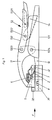
- the lower handle part 131 is designed as a carrier of the base plate 31.
- the connection of these two construction elements to one another takes place via the jaws 10 and is rigid and immovable.
- the base plate 31 has the guide groove body 311 (FIG. 4) which can be pushed into the groove opening and the clamping jaws (32) which can be moved via a joint.
- the upper handle part 132 which is movable via the articulation points 1321, 1323, has the pressure element 5 with the depressed clamping jaws 32 and the knife blade 2 on its front jaws 11.
- the jaws 11 is pivotally connected to the lower handle part 131 via the pivot point 1324.
- the pivot point 1322 in the upper handle part 132 is assigned to the catch 14, via which the two handle parts 131, 132 can be locked against one another while the pressure element 5 is firmly clamped on the lower part 31.
- This locking position can be canceled by overpressing the spring tension between the individual handle parts 131, 132, and thus the closed position of the cutting tool can be opened.
- the adjustment and fixing of the clamping jaws 32 can be carried out with a knurled screw 6.
- a pre-fixation of the jaws 32 for easier insertion and holding of the fiber bundle sheath is achieved by a compression spring 7 attached to the pressure element 5, which presses the jaws 32 when the upper handle part 132 is closed to the lower handle part 131 and thus when the pliers jaws 10, 11 are pivoted together in this way holds the barrel bundle sheath between the grooves 3111 of the guide groove body 311 and 321 of the jaws 32.
- the fine adjustment and stop adjustment of the jaws 32 can take place via the knurled screw 6.
- This construction of the cutting tool according to the invention is advantageous because it allows a very precise adjustment to the respective diameter of the fiber bundle core sheaths and gives the fitter a possibility of checking and influencing at any time.
- the knurled screw 6 is replaced by a locking mechanism, which holds the pressure element 5 with the pressed-down jaws 32 in position. This position is maintained via the latching mechanism even when the pressure of the spring 7 on the jaws 32 is reduced. This eliminates the need to close the knurled screw 6 and the clamping jaws 32 are fixed automatically when the upper handle part 132 and the lower handle part 131 or the pliers jaws 10, 11 are pivoted together.
- the upper, movable pliers jaw 11 is the carrier of the pressure element 5 with the obliquely positioned knife blade 2 attached to it.
- the cutting edge 21 of the knife blade 2 is ground in such a way that damage to the optical waveguide fibers during cutting is excluded, since the optical waveguide fibers can only come into contact with a blunt edge 22 of the knife blade 2 (FIG. 5).
- the fiber bundle sheath 1 is cut in such a way that when the pliers jaws 10, 11 are closed, the fiber bundle sheath 1 is elastically deformed by the cutting area of the knife blade 2, so that the knife blade 2 receives an arched engagement surface for cutting into the fiber bundle sheath 1.
- the extent of the deformation is determined by the height of the part of the fiber bundle sheath 1 protruding from the groove 3111 of the guide groove body 311 and advantageously this dimension is approximately one third of the diameter of the fiber bundle sheath 1.
- the compression spring 7 attached to the pressure element 5 is shaped in such a way that, in addition to the pressure work for the clamping jaws 32, it also serves as a protective bracket for the knife edge 21. Injuries to the installer are therefore excluded even when the cutting tool is open.
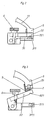
- FIG. 2 shows a section of the front view of FIG. 1.
- the upper handle part 132 has been deliberately omitted. Shown is the base plate 31 with the guide groove body 311 which can be inserted and exchanged therein.
- the clamping jaws 32 which can be pivoted and adjusted against spring pressure, are arranged with the guide groove 321 embedded therein.
- the clamping jaws 32 are fixed to the base plate 31 via the knurled screw 6.
- Fig. 3 shows the same view as Fig. 2, but in the open state with open jaws 32.
- the same features have been given the same reference numerals here.
- the opening angle of the clamping jaws 32 depends on the screw-in depth of the knurled screw 6.
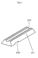
- the exchangeable guide groove body 311 with the longitudinal groove opening 3111 for receiving the fiber bundle sheath.
- this groove opening 3111 can be adapted to the different diameters of the fiber bundle sheaths 1.
- the transverse locking groove 3112 can be seen on the underside of the guide groove body 311, in which a spring plate which is fastened in the base plate 31 on the underside thereof for locking purposes can engage in a locking manner.
- FIG 5 shows the knife blade 2 without the pressure element 5 in the cut position, the fiber bundle conductor sheath being elastically deformed in the area where the cutting area is placed and the various grinding angles of the knife edge 21 being illustrated.
Landscapes
- Physics & Mathematics (AREA)
- General Physics & Mathematics (AREA)
- Optics & Photonics (AREA)
- Knives (AREA)
- Light Guides In General And Applications Therefor (AREA)
- Cable Accessories (AREA)
- Removal Of Insulation Or Armoring From Wires Or Cables (AREA)
- Auxiliary Devices For Machine Tools (AREA)
- Mechanical Coupling Of Light Guides (AREA)
Applications Claiming Priority (2)
| Application Number | Priority Date | Filing Date | Title |
|---|---|---|---|
| DE29518100U | 1995-11-15 | ||
| DE29518100U DE29518100U1 (de) | 1995-11-15 | 1995-11-15 | Schneidwerkzeug |
Publications (3)
| Publication Number | Publication Date |
|---|---|
| EP0774677A2 true EP0774677A2 (fr) | 1997-05-21 |
| EP0774677A3 EP0774677A3 (fr) | 1997-05-28 |
| EP0774677B1 EP0774677B1 (fr) | 1998-07-08 |
Family
ID=8015465
Family Applications (1)
| Application Number | Title | Priority Date | Filing Date |
|---|---|---|---|
| EP96117126A Expired - Lifetime EP0774677B1 (fr) | 1995-11-15 | 1996-10-25 | Dispositif pour enlever la gaine de protection d'une fibre optique |
Country Status (7)
| Country | Link |
|---|---|
| EP (1) | EP0774677B1 (fr) |
| AT (1) | ATE168200T1 (fr) |
| CZ (1) | CZ285946B6 (fr) |
| DE (2) | DE29518100U1 (fr) |
| DK (1) | DK0774677T3 (fr) |
| ES (1) | ES2122754T3 (fr) |
| PL (1) | PL180130B1 (fr) |
Cited By (2)
| Publication number | Priority date | Publication date | Assignee | Title |
|---|---|---|---|---|
| WO2002084352A1 (fr) * | 2001-04-11 | 2002-10-24 | Schleuniger Holding Ag | Dispositif de denudage pour fibres de verre |
| WO2010147850A1 (fr) * | 2009-06-17 | 2010-12-23 | Tyco Electronics Corporation | Outil de coupe pour accéder à une fibre à l'intérieur d'un câble à fibre optique |
Families Citing this family (2)
| Publication number | Priority date | Publication date | Assignee | Title |
|---|---|---|---|---|
| DE29719771U1 (de) * | 1997-11-07 | 1998-02-19 | Rehau Ag & Co | Schlauchförmige Schutzumhüllung für Kabelstränge |
| DE29807261U1 (de) * | 1998-04-22 | 1998-08-06 | Rehau Ag & Co | Schneidvorrichtung |
Citations (2)
| Publication number | Priority date | Publication date | Assignee | Title |
|---|---|---|---|---|
| US4972581A (en) | 1987-08-05 | 1990-11-27 | Alcatel Na, Inc. | Optical fiber access tool |
| DE4236251A1 (de) | 1992-10-20 | 1994-04-21 | Hoechst Ag | Vorrichtung zum Entfernen der Schutzhülle von Optischen Fasern |
Family Cites Families (8)
| Publication number | Priority date | Publication date | Assignee | Title |
|---|---|---|---|---|
| GB525691A (en) * | 1939-02-25 | 1940-09-03 | Harry St John Crawford Anderso | An improved device for stripping insulation from electric cables and wires |
| DE1465579A1 (de) * | 1963-08-13 | 1969-05-22 | Josef Gigler Sen | Kombinationszange |
| DE3139282A1 (de) * | 1981-10-02 | 1983-04-21 | Josef 4715 Ascheberg Krampe | Abmantelungszange |
| US4447949A (en) * | 1982-09-30 | 1984-05-15 | Kane Michael W | Wire stripper |
| DE3802577A1 (de) * | 1988-01-29 | 1989-08-03 | Philips Patentverwaltung | Vorrichtung zum abloesen einer auf lichtwellenleiter aufgebrachten beschichtung |
| JPH02134501U (fr) * | 1989-04-14 | 1990-11-08 | ||
| DE4111845C2 (de) * | 1991-04-11 | 1997-09-11 | Hermann Dietrich Molsner | Vorrichtung zum Längsauftrennen von Rohren, insbesondere von Probenrohren aus Kunststoff |
| DE4416817A1 (de) * | 1994-05-13 | 1995-11-16 | Rehau Ag & Co | Schneidwerkzeug |
-
1995
- 1995-11-15 DE DE29518100U patent/DE29518100U1/de not_active Expired - Lifetime
-
1996
- 1996-10-25 AT AT96117126T patent/ATE168200T1/de not_active IP Right Cessation
- 1996-10-25 ES ES96117126T patent/ES2122754T3/es not_active Expired - Lifetime
- 1996-10-25 DK DK96117126T patent/DK0774677T3/da active
- 1996-10-25 EP EP96117126A patent/EP0774677B1/fr not_active Expired - Lifetime
- 1996-10-25 DE DE59600323T patent/DE59600323D1/de not_active Expired - Fee Related
- 1996-11-12 CZ CZ963320A patent/CZ285946B6/cs not_active IP Right Cessation
- 1996-11-13 PL PL96316954A patent/PL180130B1/pl not_active IP Right Cessation
Patent Citations (2)
| Publication number | Priority date | Publication date | Assignee | Title |
|---|---|---|---|---|
| US4972581A (en) | 1987-08-05 | 1990-11-27 | Alcatel Na, Inc. | Optical fiber access tool |
| DE4236251A1 (de) | 1992-10-20 | 1994-04-21 | Hoechst Ag | Vorrichtung zum Entfernen der Schutzhülle von Optischen Fasern |
Cited By (2)
| Publication number | Priority date | Publication date | Assignee | Title |
|---|---|---|---|---|
| WO2002084352A1 (fr) * | 2001-04-11 | 2002-10-24 | Schleuniger Holding Ag | Dispositif de denudage pour fibres de verre |
| WO2010147850A1 (fr) * | 2009-06-17 | 2010-12-23 | Tyco Electronics Corporation | Outil de coupe pour accéder à une fibre à l'intérieur d'un câble à fibre optique |
Also Published As
| Publication number | Publication date |
|---|---|
| EP0774677A3 (fr) | 1997-05-28 |
| CZ285946B6 (cs) | 1999-12-15 |
| CZ332096A3 (cs) | 1999-09-15 |
| PL316954A1 (en) | 1997-05-26 |
| DK0774677T3 (da) | 1999-04-19 |
| DE59600323D1 (de) | 1998-08-13 |
| EP0774677B1 (fr) | 1998-07-08 |
| ATE168200T1 (de) | 1998-07-15 |
| PL180130B1 (pl) | 2000-12-29 |
| ES2122754T3 (es) | 1998-12-16 |
| DE29518100U1 (de) | 1996-01-04 |
Similar Documents
| Publication | Publication Date | Title |
|---|---|---|
| DE2642008C3 (de) | Handzange zum Abisolieren von Leiterenden | |
| EP1096628B1 (fr) | Méthode et dispositif pour dépouiller l'écran d'un câble | |
| DE10132413C2 (de) | Verfahren und Zange zum Schneiden amorpher Lichtwellenleiterkabel | |
| DE2402187A1 (de) | Geraet zum abstreifen der verkleidung von bezogenen leitungen und dgl. | |
| EP0307491B1 (fr) | Instrument chirurgical pour insérer des tiges en acier dans l'os | |
| DE3030610C2 (de) | Zangenartiges Werkzeug zum Abisolieren der isolierenden Umhüllung von elektrisch isolierten Leitern | |
| EP0285699B1 (fr) | Pince pour déplacer du matériel flexible sous forme de cordes | |
| DE3241530A1 (de) | Abisolierzange | |
| DE2517873C3 (de) | Einstellbare Abisolierzange | |
| DE2138708B2 (de) | Montagewerkzeug für Außensicherungsringe | |
| DE3335728A1 (de) | Handbetaetigungszange | |
| EP1319456A1 (fr) | Découpeur de câbles | |
| EP0774677B1 (fr) | Dispositif pour enlever la gaine de protection d'une fibre optique | |
| DE2749342A1 (de) | Werkzeug zum spannen und schneiden von selbstverriegelungsbaendern | |
| EP1356326A1 (fr) | Outil en forme de pince et procede permettant de sectionner des cables a fibres optiques | |
| DE2930612A1 (de) | Verfahren und vorrichtung zum abisolieren von elektrischen leitern bzw. abmanteln von elektrischen kabeln | |
| DE202009014841U1 (de) | Öffnungshilfe zum Öffnen von Energieführungsketten | |
| EP0952651A1 (fr) | Dispositif à couper | |
| DE2705829B2 (de) | Verfahren und Vorrichtung zum Abisolieren eines Endabschnittes eines litzenförmigen Leiters | |
| CH671724A5 (fr) | ||
| DE3512065C1 (de) | Vorrichtung zum Entfernen eines Abschnittes einer Ummantelung von im wesentlichen stangenförmigen Gegenständen, insbesondere elektrischen Kabeln | |
| DE10056780A1 (de) | Schneidvorrichtung zum Trennen von Lichtwellenleitern | |
| DE4441632C2 (de) | Spanneinrichtung für Baumständer | |
| EP1117163A2 (fr) | Couteau pour câble | |
| DE4122235C2 (fr) |
Legal Events
| Date | Code | Title | Description |
|---|---|---|---|
| PUAI | Public reference made under article 153(3) epc to a published international application that has entered the european phase |
Free format text: ORIGINAL CODE: 0009012 |
|
| PUAL | Search report despatched |
Free format text: ORIGINAL CODE: 0009013 |
|
| AK | Designated contracting states |
Kind code of ref document: A2 Designated state(s): AT BE CH DE DK ES FR GB IT LI NL SE |
|
| AK | Designated contracting states |
Kind code of ref document: A3 Designated state(s): AT BE CH DE DK ES FR GB IT LI NL SE |
|
| 17P | Request for examination filed |
Effective date: 19970428 |
|
| 17Q | First examination report despatched |
Effective date: 19971010 |
|
| GRAG | Despatch of communication of intention to grant |
Free format text: ORIGINAL CODE: EPIDOS AGRA |
|
| GRAG | Despatch of communication of intention to grant |
Free format text: ORIGINAL CODE: EPIDOS AGRA |
|
| GRAH | Despatch of communication of intention to grant a patent |
Free format text: ORIGINAL CODE: EPIDOS IGRA |
|
| GRAH | Despatch of communication of intention to grant a patent |
Free format text: ORIGINAL CODE: EPIDOS IGRA |
|
| GRAA | (expected) grant |
Free format text: ORIGINAL CODE: 0009210 |
|
| AK | Designated contracting states |
Kind code of ref document: B1 Designated state(s): AT BE CH DE DK ES FR GB IT LI NL SE |
|
| REF | Corresponds to: |
Ref document number: 168200 Country of ref document: AT Date of ref document: 19980715 Kind code of ref document: T |
|
| ITF | It: translation for a ep patent filed |
Owner name: DE DOMINICIS & MAYER S.R.L. |
|
| REG | Reference to a national code |
Ref country code: CH Ref legal event code: EP |
|
| REF | Corresponds to: |
Ref document number: 59600323 Country of ref document: DE Date of ref document: 19980813 |
|
| GBT | Gb: translation of ep patent filed (gb section 77(6)(a)/1977) |
Effective date: 19980917 |
|
| ET | Fr: translation filed | ||
| REG | Reference to a national code |
Ref country code: ES Ref legal event code: FG2A Ref document number: 2122754 Country of ref document: ES Kind code of ref document: T3 |
|
| REG | Reference to a national code |
Ref country code: DK Ref legal event code: T3 |
|
| PLBE | No opposition filed within time limit |
Free format text: ORIGINAL CODE: 0009261 |
|
| STAA | Information on the status of an ep patent application or granted ep patent |
Free format text: STATUS: NO OPPOSITION FILED WITHIN TIME LIMIT |
|
| 26N | No opposition filed | ||
| REG | Reference to a national code |
Ref country code: GB Ref legal event code: IF02 |
|
| PGFP | Annual fee paid to national office [announced via postgrant information from national office to epo] |
Ref country code: BE Payment date: 20050929 Year of fee payment: 10 |
|
| PGFP | Annual fee paid to national office [announced via postgrant information from national office to epo] |
Ref country code: SE Payment date: 20051003 Year of fee payment: 10 Ref country code: DK Payment date: 20051003 Year of fee payment: 10 Ref country code: CH Payment date: 20051003 Year of fee payment: 10 |
|
| PGFP | Annual fee paid to national office [announced via postgrant information from national office to epo] |
Ref country code: FR Payment date: 20051005 Year of fee payment: 10 |
|
| PGFP | Annual fee paid to national office [announced via postgrant information from national office to epo] |
Ref country code: GB Payment date: 20051014 Year of fee payment: 10 Ref country code: ES Payment date: 20051014 Year of fee payment: 10 |
|
| PGFP | Annual fee paid to national office [announced via postgrant information from national office to epo] |
Ref country code: NL Payment date: 20051207 Year of fee payment: 10 |
|
| PG25 | Lapsed in a contracting state [announced via postgrant information from national office to epo] |
Ref country code: SE Free format text: LAPSE BECAUSE OF NON-PAYMENT OF DUE FEES Effective date: 20061026 |
|
| PG25 | Lapsed in a contracting state [announced via postgrant information from national office to epo] |
Ref country code: LI Free format text: LAPSE BECAUSE OF NON-PAYMENT OF DUE FEES Effective date: 20061031 Ref country code: DK Free format text: LAPSE BECAUSE OF NON-PAYMENT OF DUE FEES Effective date: 20061031 Ref country code: CH Free format text: LAPSE BECAUSE OF NON-PAYMENT OF DUE FEES Effective date: 20061031 |
|
| PG25 | Lapsed in a contracting state [announced via postgrant information from national office to epo] |
Ref country code: NL Free format text: LAPSE BECAUSE OF NON-PAYMENT OF DUE FEES Effective date: 20070501 |
|
| REG | Reference to a national code |
Ref country code: CH Ref legal event code: PL |
|
| EUG | Se: european patent has lapsed | ||
| GBPC | Gb: european patent ceased through non-payment of renewal fee |
Effective date: 20061025 |
|
| NLV4 | Nl: lapsed or anulled due to non-payment of the annual fee |
Effective date: 20070501 |
|
| REG | Reference to a national code |
Ref country code: FR Ref legal event code: ST Effective date: 20070629 |
|
| PG25 | Lapsed in a contracting state [announced via postgrant information from national office to epo] |
Ref country code: GB Free format text: LAPSE BECAUSE OF NON-PAYMENT OF DUE FEES Effective date: 20061025 |
|
| BERE | Be: lapsed |
Owner name: *REHAU A.G. + CO. Effective date: 20061031 |
|
| REG | Reference to a national code |
Ref country code: ES Ref legal event code: FD2A Effective date: 20061026 |
|
| PG25 | Lapsed in a contracting state [announced via postgrant information from national office to epo] |
Ref country code: FR Free format text: LAPSE BECAUSE OF NON-PAYMENT OF DUE FEES Effective date: 20061031 Ref country code: ES Free format text: LAPSE BECAUSE OF NON-PAYMENT OF DUE FEES Effective date: 20061026 |
|
| PGFP | Annual fee paid to national office [announced via postgrant information from national office to epo] |
Ref country code: IT Payment date: 20080926 Year of fee payment: 13 |
|
| PGFP | Annual fee paid to national office [announced via postgrant information from national office to epo] |
Ref country code: DE Payment date: 20081031 Year of fee payment: 13 |
|
| PGFP | Annual fee paid to national office [announced via postgrant information from national office to epo] |
Ref country code: AT Payment date: 20081020 Year of fee payment: 13 |
|
| PG25 | Lapsed in a contracting state [announced via postgrant information from national office to epo] |
Ref country code: BE Free format text: LAPSE BECAUSE OF FAILURE TO SUBMIT A TRANSLATION OF THE DESCRIPTION OR TO PAY THE FEE WITHIN THE PRESCRIBED TIME-LIMIT Effective date: 20061031 |
|
| PG25 | Lapsed in a contracting state [announced via postgrant information from national office to epo] |
Ref country code: DE Free format text: LAPSE BECAUSE OF NON-PAYMENT OF DUE FEES Effective date: 20100501 |
|
| PG25 | Lapsed in a contracting state [announced via postgrant information from national office to epo] |
Ref country code: AT Free format text: LAPSE BECAUSE OF NON-PAYMENT OF DUE FEES Effective date: 20091025 |
|
| PG25 | Lapsed in a contracting state [announced via postgrant information from national office to epo] |
Ref country code: IT Free format text: LAPSE BECAUSE OF NON-PAYMENT OF DUE FEES Effective date: 20091025 |