EP0774153B1 - Plattenantrieb mit eingebetteten schwingspulenmagnetplatten - Google Patents
Plattenantrieb mit eingebetteten schwingspulenmagnetplatten Download PDFInfo
- Publication number
- EP0774153B1 EP0774153B1 EP95927487A EP95927487A EP0774153B1 EP 0774153 B1 EP0774153 B1 EP 0774153B1 EP 95927487 A EP95927487 A EP 95927487A EP 95927487 A EP95927487 A EP 95927487A EP 0774153 B1 EP0774153 B1 EP 0774153B1
- Authority
- EP
- European Patent Office
- Prior art keywords
- magnet
- disk drive
- assembly
- windings
- plate
- Prior art date
- Legal status (The legal status is an assumption and is not a legal conclusion. Google has not performed a legal analysis and makes no representation as to the accuracy of the status listed.)
- Expired - Lifetime
Links
- 238000004804 winding Methods 0.000 claims description 39
- 230000004907 flux Effects 0.000 claims description 11
- 238000004519 manufacturing process Methods 0.000 claims description 10
- 238000004512 die casting Methods 0.000 claims description 7
- 239000000463 material Substances 0.000 claims description 3
- 230000000295 complement effect Effects 0.000 claims 2
- 239000012768 molten material Substances 0.000 claims 2
- 238000005304 joining Methods 0.000 claims 1
- 230000002463 transducing effect Effects 0.000 description 9
- XAGFODPZIPBFFR-UHFFFAOYSA-N aluminium Chemical compound [Al] XAGFODPZIPBFFR-UHFFFAOYSA-N 0.000 description 7
- 229910052782 aluminium Inorganic materials 0.000 description 7
- 238000003860 storage Methods 0.000 description 6
- 230000008859 change Effects 0.000 description 5
- 230000001965 increasing effect Effects 0.000 description 5
- 238000000034 method Methods 0.000 description 5
- 230000008569 process Effects 0.000 description 5
- GXVMAQACUOSFJF-UHFFFAOYSA-N 1,3-dichloro-5-(2-chlorophenyl)benzene Chemical compound ClC1=CC(Cl)=CC(C=2C(=CC=CC=2)Cl)=C1 GXVMAQACUOSFJF-UHFFFAOYSA-N 0.000 description 4
- 230000008901 benefit Effects 0.000 description 4
- 229910000831 Steel Inorganic materials 0.000 description 3
- 239000012530 fluid Substances 0.000 description 3
- 230000005415 magnetization Effects 0.000 description 3
- 239000010959 steel Substances 0.000 description 3
- 230000000712 assembly Effects 0.000 description 2
- 238000000429 assembly Methods 0.000 description 2
- 238000010276 construction Methods 0.000 description 2
- 230000001419 dependent effect Effects 0.000 description 2
- 239000000696 magnetic material Substances 0.000 description 2
- 229910001209 Low-carbon steel Inorganic materials 0.000 description 1
- QJVKUMXDEUEQLH-UHFFFAOYSA-N [B].[Fe].[Nd] Chemical compound [B].[Fe].[Nd] QJVKUMXDEUEQLH-UHFFFAOYSA-N 0.000 description 1
- 229910045601 alloy Inorganic materials 0.000 description 1
- 239000000956 alloy Substances 0.000 description 1
- 238000013500 data storage Methods 0.000 description 1
- 230000001939 inductive effect Effects 0.000 description 1
- 229910001172 neodymium magnet Inorganic materials 0.000 description 1
- 230000004044 response Effects 0.000 description 1
Images


Classifications
-
- G—PHYSICS
- G11—INFORMATION STORAGE
- G11B—INFORMATION STORAGE BASED ON RELATIVE MOVEMENT BETWEEN RECORD CARRIER AND TRANSDUCER
- G11B25/00—Apparatus characterised by the shape of record carrier employed but not specific to the method of recording or reproducing, e.g. dictating apparatus; Combinations of such apparatus
- G11B25/04—Apparatus characterised by the shape of record carrier employed but not specific to the method of recording or reproducing, e.g. dictating apparatus; Combinations of such apparatus using flat record carriers, e.g. disc, card
-
- G—PHYSICS
- G11—INFORMATION STORAGE
- G11B—INFORMATION STORAGE BASED ON RELATIVE MOVEMENT BETWEEN RECORD CARRIER AND TRANSDUCER
- G11B25/00—Apparatus characterised by the shape of record carrier employed but not specific to the method of recording or reproducing, e.g. dictating apparatus; Combinations of such apparatus
- G11B25/04—Apparatus characterised by the shape of record carrier employed but not specific to the method of recording or reproducing, e.g. dictating apparatus; Combinations of such apparatus using flat record carriers, e.g. disc, card
- G11B25/043—Apparatus characterised by the shape of record carrier employed but not specific to the method of recording or reproducing, e.g. dictating apparatus; Combinations of such apparatus using flat record carriers, e.g. disc, card using rotating discs
Definitions
- the present invention relates to a data storage device, and more particularly, to a disk drive including voice coil motor magnet plates formed integrally with the base and/or cover of the disk drive during the drive fabrication process.
- Winchester-type disk drives operate by transferring data between read/write transducing heads and respective data tracks on magnetic storage disks.
- the transducing heads are supported by an actuator assembly, which is provided to pivot the heads across the surfaces of the disks. Pivoting of the actuator assembly and transducing heads is generally accomplished by a voice coil motor (“VCM”) provided as part of the actuator assembly at an end of the actuator assembly opposite the transducing heads.
- VCM voice coil motor
- a VCM is typically comprised of a permanent magnet stationarily mounted within the drive, and electrical windings fixedly mounted to the actuator assembly, adjacent to the magnet, so as to pivot with the actuator assembly.
- the windings are located within a magnetic field set up by the magnet, and, upon introduction of an electric current through the windings, the magnetic field will exert a force on the windings causing the actuator assembly and transducing heads to pivot.
- the VCM is coupled to control electronics, which control the current through the windings, and thus control the positioning of the actuator assembly and transducing heads with respect to the storage disk.
- the time it takes to pivot the actuator assembly so as to move the transducing heads between different data tracks on the storage disk in response to control signals is referred to as the drive seek time.
- the seek time of a disk drive has become the major factor limiting the rate at which data is transferred between the heads and disks.
- Seek time is primarily dependent on the torque which can be generated in the VCM to pivot the actuator assembly between data tracks on the disk.
- the voice coil magnet assembly also includes magnetically permeable plates adjacent to the magnet, which plates are fixedly mounted within the drive housing.
- Conventional magnet assemblies have further included magnetically permeable return posts extending between the top and bottom magnet plates. The magnet plates and the return posts together provide a closed magnetic field loop for the magnetic flux lines emanating from the permanent magnet. This configuration was provided to maximize the magnetic field in the vicinity of the actuator as windings.
- the magnetic field in this region contributes most directly to the strength of the torcue generated by the VCM.
- a disk drive including VCM magnet plates formed integrally with the base and/or cover of the disk drive.
- VCM magnet plates formed integrally with the base and/or cover of the disk drive.
- the steel magnet plates are placed in proper position in the base and cover die casting, and then the molten aluminum is injected to form the base and cover.
- the magnet plates are integral with the base and cover and no fluid leakage can occur around the boundary between the top magnet and cover, or around the boundary between the bottom magnet and base.
- the plates may be formed with a plurality of grooves, into which the molten aluminum flows during the fabrication process, to thereby ensure that the plates will remain fixedly secure to the base and cover, respectively.
- Forming the magnet plates integrally with the base and/or cover allows omission the magnet side posts, normally required to provide a closed magnetic field loop.
- Providing a VCM magnet assembly without return posts offers several advantages, including faster seek times, a more simple and less expensive VCM design, and greater control over the magnetic field intensity.
- the decrease in the magnetic field due to the absence of the side post return paths is compensated for by having thicker magnet plates and magnets.
- the increased thickness of the plates and magnets is allowed by forming the plates in the base and cover, as opposed to adjacent to the base and cover.
- the top and/or bottom magnet plate may be extended to the area surrounding the spindle motor such that the actuator and spindle motor are both mounted to the top and/or bottom magnet plates.
- Figs. 1 - 5 relate in general to a disk drive including voice coil magnet plates formed integrally with the base and/or cover of the disk drive during the drive fabrication process. It is understood that the present invention may operate with disk drives of various designs and sizes.
- a disk drive 20 including a plurality of storage disks 22 a-d and a plurality of read/write heads 24 a-h .
- One head 24 is provided for each of the eight surfaces of disks 22 a-d . It is understood that the disk drive 20 may include more or less than the above-disclosed numbers of disks and heads.
- Each read/write head 24 is comprised of a transducer mounted to a slider. The slider of each head 24 a-h is in turn supported on actuator arms 28 a-h .
- the transducer may be a conventional inductive transducing element, or in an alternative embodiment, may be a magneto-resistive (MR) transducing element.
- MR magneto-resistive
- the drive 20 further includes an actuator assembly 27 having actuator arms 28 a-h .
- Actuator assembly 27 is provided to pivot around pin 30 by a voice coil motor (“VCM”) described hereinafter.
- VCM voice coil motor
- disks 22 a-d are rotated by a spindle motor 29 and actuator arms 28 a-h pivot read/write head 24 a-h across the surface of the disks so that data is transferred between the read/write heads 24 a-h and the disks 22 a-d in a plurality of concentric data tracks.
- the drive 20 further includes a printed circuit board (PCB) 34 having the data transfer and control electronics for the drive.
- PCB printed circuit board
- the head and disk assembly (“HDA") is preferably enclosed within a base 36 and a cover 38, which fit together to form a sealed environment for the HDA.
- the PCB is preferably located on an underside of the base 36.
- the base and cover are formed from aluminum.
- the VCM includes magnet assembly 40 and conductive windings 42. Windings 42 are fixedly mounted between actuator assembly sub-arms 27a and 27b, and are provided to receive an electric current from PCB 34.
- Magnet assembly 40 includes top and bottom magnets 44 and 46, respectively, which magnets are spaced apart from each other such that windings 42 may be located therebetween.
- magnets 44 and 46 may be comprised of a conventional permanent magnetic material, such as a neodymium-iron-boron alloy or comparable material. Both magnets include top and bottom surfaces substantially parallel to a plane in which the actuator assembly pivots.
- Magnet 44 may have a direction of magnetization substantially perpendicular to the top and bottom surfaces, and may be magnetized such that one-half of the magnet has a top-to-bottom north-south magnetization, and the other half has a top-to-bottom south-north magnetization.
- Magnet 46 is preferably provided with the same magnetic orientation. Thus, when provided as shown in Fig. 3, a magnetic field "B" is set up with flux lines flowing from a north pole of bottom magnet 46 to a south pole of top magnet 44, and from a north pole of top magnet 44 to a south pole of bottom magnet 46.
- the magnetic field B will exert a force on the windings perpendicular to the direction of the flux lines.
- the windings 42 are fixedly mounted to the actuator assembly 27, and the force exerted by the field B causes actuator assembly 27, as well as heads 24 a-h attached thereto, to pivot across the surface of the disks 22 a-d .
- the duration and direction of the current through windings 42 is controlled by PCB 34, so as to accurately position the heads 24 a-h over the desired data track on the respective storage disks 22 a-d .
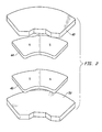
- the present invention further includes an upper magnet plate 48 to which top magnet 44 is secured, and lower magnet plate 50 to which bottom magnet 46 is secured.
- Upper and lower magnet plates 48 and 50 are formed of a magnetically permeable material, such as low carbon steel for example, and function to transmit the flux lines within both magnets from one-half of each magnet ( i.e. , the north side) to the other half of each magnet ( i.e. , the south side), and through the air gap between the upper and lower magnets.
- the magnet plates 48 and 50 are formed within and as part of the cover and base, respectively.
- the preformed magnet plates are positioned within the die castings used to form the base and cover. Once the magnet plates are properly positioned, the molten aluminum is injected into the die castings, and forms around the magnet plates.
- the upper and lower magnet plates are formed as part of and integrally with the cover and base, respectively, and there are no gaps at the boundary between the magnet plates and the cover and base for fluid to escape. Consequently, a sealed environment for the HDA may be maintained.
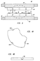
- upper and lower magnet plates may be formed with notches 52a, 52b and 52c.
- the aluminum flows into the notches 52.
- the notches firmly secure the upper and lower magnet plates to the cover and base, respectively.
- the upper and lower magnet plates may be formed with other notch configurations, or with other geometries which will serve to interlock and secure the plates to the cover and base.
- both the magnet plates 48 and 50 and magnets 44 and 46 may be of a greater thickness as compared to magnet plates and magnets within conventional disk drives of the same size.
- an 8.75 centimeter (31 ⁇ 2 inch) form factor disk drive having a total height (not including the PCB 34) of approximately 1.6625 centimeters (0.665 inches) the thicknesses of the upper and lower magnet plates and top and bottom magnets in a preferred embodiment are as follows:
- the increased thicknesses of the magnets and magnet plates in the VCM allow for an increased magnetic field B in the gap between the top and bottom magnets 44 and 46.
- the magnetic field within the gap has been experimentally determined to be 0.7976 T (7976 Gauss).
- the magnetic field within the gap has been experimentally determined to be approximately 0.7565 T (7565 Gauss). Therefore, even without return posts, the present invention offers an increase in the magnetic field across the gap of approximately 0.411 T (411 Gauss).
- Omitting the return posts utilized in conventional VCM magnet assemblies offers several advantages.
- the absence of return posts lowers the inductance within windings 42, thereby increasing the rate at which the current may change through windings 42. A quicker rate of current change provides quicker seek times.
- the absence of return posts allows better control and greater uniformity of the magnetic field properties.
- the intensity of a magnetic field in conventional voice coil motors is highly dependent on the height of the return posts.
- the height of the return posts vary from one voice coil to the next, and therefore, the intensity of the magnetic field varies from one drive to the next. By omitting the return posts, the intensity of the magnetic field from one voice coil to the next remains relatively uniform.
- the presence of return posts cause a variation, or a non-linear profile of the magnetic field intensity.
- a voice coil viewed from the perspective shown in Fig. 3, a cross-section of the windings at two different positions of the actuator are shown.
- Points 54a and 54b represent a first position of the windings where they are at the horizontal center of the magnet assembly 40.
- Points 56a and 56b represent a second position of the windings where they are at a side of magnet assembly 40.
- the second case corresponds to the situation where the heads 24 a-h are positioned at the inner or outer diameter of the disks 22 a-d .
- the torque generated by the windings at the first position shown by points 54a and 54b will be higher than the torque generated by the windings at the second position shown by points 56a and 56b.
- the difference in the torque generated by the windings from the first position to the second position is greatly reduced.
- the intensity of the magnetic field across the length of the gap is more uniform and linear. This provides a relatively uniform movement of the windings through the gap, and in turn, greater uniformity of and control over the movement of the heads 24 a-h over the surface of the storage disks 22 a-d .
- the present invention provides a further advantage in that the omission of return posts allows for a simpler design with less parts and which is less expensive to manufacture.
- the lower magnet plate 50 may be enlarged so that both actuator assembly 27 and the spindle motor 29 are mounted to the base through a pair of mounting screws fitted through holes in the steel magnet plate 50.
- the cover may also contain an enlarged magnet plate 48 so that both the actuator assembly 27 and the spindle motor 29 are mounted to the cover through a pair of mounting screws fitted through holes in the steel magnet plate 48.
Landscapes
- Moving Of Heads (AREA)
Claims (12)
- Magnetanordnung (40) zur Ausübung einer Kraft auf elektrisch leitende Wicklungen (42) einer Betätigungsanordnung (27) in einem Plattenantrieb (20), wobei der Plattenantrieb (20) eine Basis (36) und eine Abdeckung (38) einschließt, die Magnetanordnung (40) wenigstens einen Magneten (44, 46) zur Erzeugung des Magnetfeldes und wenigstens eine Magnetplatte (48, 50) aufweist, worin bei Anordnung in dem Plattenantrieb der wenigstens eine Magnet neben den Wicklungen (42) angeordnet ist und die wenigstens eine Magnetplatte neben dem wenigstens einen Magneten (44, 46) auf einer Seite des wenigstens einen Magneten (44, 46) gegenüber den Wicklungen (42) liegt, um Magnetfluß des Magnetfeldes zwischen Polen des wenigstens einen Magneten (44, 46) zu überführen, dadurch gekennzeichnet, daß die wenigstens eine Magnetplatte (48, 50) wenigstens eine Kerbe (52) zur Verankerung mit der Basis (36) und/oder Abdeckung des Plattenantriebs (38) enthält, wenn die Basis (36) und/oder die Abdeckung (38) gegossen wird, so daß die wenigstens eine Magnetplatte (48, 50) einstückig als Teil der Basis (36) und/oder der Abdeckung (38) ausgebildet werden kann.
- Magnetanordnung (40) nach Anspruch 1, weiterhin mit einem zweiten Magneten (46) komplementär zu dem wenigstens einen Magneten, so daß bei Anordnung in dem Plattenantrieb der zweite Magnet neben den Wicklungen (42) auf einer Seite dieser Wicklungen (42) gegenüber dem wenigstens einen Magneten (46) liegt, um eine Magnetkraft auf die Wicklungen (42) bei Einführung eines elektrischen Stromes durch diese Windungen (42) auszuüben, und einer zweiten Magnetplatte (50) komplementär zu der wenigstens einen Magnetplatte, so daß bei Anordnung in dem Plattenantrieb die zweite Magnetplatte neben dem zweiten Magneten (46) auf einer Seite des zweiten Magneten (46) gegenüber den Wicklungen (42) liegt, um den Magnetfluß zwischen Polen des zweiten Magneten (46) zu überführen, so daß die zweite Magnetplatte (50) einstückig als Teil der anderen der Basis (36) oder der Abdeckung (38) als jener, in welcher die wenigstens eine Magnetplatte ausgebildet ist, ausgebildet werden kann.
- Magnetanordnung (40) nach Anspruch 1, bei der die wenigstens eine Magnetplatte (48) eine Dicke von etwa 0,48125 cm (0,1925 in) hat.
- Magnetanordnung (40) nach Anspruch 1, bei der der wenigstens eine Magnet (44) eine Dicke von etwa 0,225 cm (0,09 in) hat.
- Magnetanordnung (40) nach Anspruch 1, bei der das Magnetfeld eine Intensität von nicht weniger als etwa 0,7976 T (7976 Gauss) hat.
- Magnetanordnung (40) zur Ausübung einer Kraft auf elektrisch leitende Wicklungen (42) einer Betätigungsanordnung (27) in einem Plattenantrieb (20), wobei der Plattenantrieb (20) eine Basis (36) und eine Abdeckung (38) einschließt, die Magnetanordnung (40) wenigstens einen Magneten (44, 46) zur Erzeugung des Magnetfeldes und wenigstens eine Magnetplatte (48, 50) aufweist, wobei bei Anordnung in dem Plattenantrieb der wenigstens eine Magnet neben den Wicklungen (42) liegt und die wenigstens eine Magnetplatte neben dem wenigstens einen Magneten (44, 46) auf einer Seite des wenigstens einen Magneten (44, 46) gegenüber den Wicklungen (42) liegt, um Magnetfluß des Magnetfeldes zwischen Polen des wenigstens einen Magneten (44, 46) zu überführen, dadurch gekennzeichnet, daß die Magnetanordnung (40) keine magnetisch durchlässigen Rückkehrständer hat und die wenigstens eine Magnetplatte aus magnetisch durchlässigem Material gebildet ist und eine derartige Dicke hat, daß, wenn die wenigstens eine Magnetplatte (48, 50) einstückig als Teil der Basis (36) und/oder der Abdeckung (38) ausgebildet ist, die Magnetplatte dazu dient, Magnetfluß zwischen Polen des wenigstens einen Magneten zu überführen.
- Magnetanordnung (40) nach Anspruch 6, bei der die wenigstens eine Magnetplatte (48, 50) eine Dicke von etwa 0,48125 cm (0,1925 in) hat.
- Magnetanordnung (40) nach Anspruch 6, bei der der wenigstens eine Magnet (44, 46) eine Dicke von etwa 0,225 cm (0,09 in) hat.
- Magnetanordnung (40) nach Anspruch 6, bei der das Magnetfeld eine Intensität von nicht weniger als 0,7976 T (7976 Gauss) hat.
- Verfahren zur Herstellung eines Plattenantriebsgehäuses mit einer Magnetanordnung (40) für einen Schwingspulenmotor des Plattenantriebs (20 mit den Stufen, in den maneine erste Magnetplatte (48) in einer Druckgießform für eine Abdeckung (38) des Plattenantriebs (20 anordnet,geschmolzenes Material, aus welchem die Abdeckung (38) gemacht wird, in die Gießform um die erste Magnetplatte (48) herum einführt,eine zweite Magnetplatte (50) in einer Druckgießform für eine Basis (36) des Plattenantriebs (20) anordnet,geschmolzenes Material, aus welchem die Basis (36) gemacht wird, in die Druckgießform um die zweite Magnetplatte (50) herum einführt,wenigstens einen Magneten (44, 46) an der ersten und/oder zweiten Magnetplatte (48, 50) befestigt unddie Basis (36) mit der Abdeckung (38) verbindet, um eine abgedichtete Umgebung für den Plattenantrieb (20) zu bekommen.
- Magnetanordnung (40) nach Anspruch 1, bei der die Magnetanordnung (40) keinen magnetisch durchlässigen Rückkehrträger enthält.
- Plattenantriebgehäuse mit einer ersten und einer zweiten Oberfläche, wobei das Gehäuse eine abgedichtete Umgebung für den Plattenantrieb (20) begrenzt und die erste Oberfläche des Gehäuses innerhalb und die zweite Oberfläche des Gehäuses außerhalb der abgedichteten Umgebung ist und das Gehäuse dadurch gekennzeichnet ist, daß eine Magnetplatte (48, 50) einstückig als Teil des Gehäuses ausgebildet ist, wobei diese Magnetplatte (48, 50) Magnetfluß zwischen Polen eines Magneten einer Betätigungsanordnung (27) des Plattenantriebs (20) überführen kann, und die Magnetplatte (48, 50) wenigstens eine Kerbe (52) zur Verankerung mit dem Gehäuse, wenn es gegossen wird, aufweist.
Applications Claiming Priority (3)
| Application Number | Priority Date | Filing Date | Title |
|---|---|---|---|
| US28436894A | 1994-08-02 | 1994-08-02 | |
| US284368 | 1994-08-02 | ||
| PCT/US1995/009479 WO1996004656A1 (en) | 1994-08-02 | 1995-07-28 | Disk drive including embedded voice coil magnet plates |
Publications (2)
| Publication Number | Publication Date |
|---|---|
| EP0774153A1 EP0774153A1 (de) | 1997-05-21 |
| EP0774153B1 true EP0774153B1 (de) | 1998-08-26 |
Family
ID=23089945
Family Applications (1)
| Application Number | Title | Priority Date | Filing Date |
|---|---|---|---|
| EP95927487A Expired - Lifetime EP0774153B1 (de) | 1994-08-02 | 1995-07-28 | Plattenantrieb mit eingebetteten schwingspulenmagnetplatten |
Country Status (6)
| Country | Link |
|---|---|
| US (1) | US6125016A (de) |
| EP (1) | EP0774153B1 (de) |
| JP (1) | JPH10506213A (de) |
| KR (1) | KR100390052B1 (de) |
| DE (1) | DE69504358T2 (de) |
| WO (1) | WO1996004656A1 (de) |
Families Citing this family (16)
| Publication number | Priority date | Publication date | Assignee | Title |
|---|---|---|---|---|
| US6304421B1 (en) * | 1999-01-21 | 2001-10-16 | Seagate Technology Llc | Voice coil motor plate for a disc drive |
| US6549379B1 (en) * | 2000-02-07 | 2003-04-15 | Seagate Technology Llc | Unified disc drive top cover and voice coil motor pole |
| US6577474B2 (en) * | 2000-02-09 | 2003-06-10 | Seagate Technology Llc | Integrated voice coil motor assembly for a disc drive |
| JP4678917B2 (ja) * | 2000-06-22 | 2011-04-27 | パナソニック株式会社 | ディスク装置 |
| US6735054B2 (en) | 2000-08-04 | 2004-05-11 | Seagate Technology Llc | Low cost overmolded magnet and pole assembly |
| US20030218827A1 (en) * | 2002-05-23 | 2003-11-27 | Seagate Technology Llc | Disc drive top cover having an over-molded top pole |
| JP4199199B2 (ja) | 2003-04-16 | 2008-12-17 | 富士通株式会社 | 記録媒体駆動装置 |
| JP2006048764A (ja) * | 2004-07-30 | 2006-02-16 | Toshiba Corp | ディスク装置 |
| US7609486B1 (en) * | 2005-04-25 | 2009-10-27 | Western Digital Technologies, Inc. | Disk drive including a post attached to a disk drive base and a cover for limiting rotation of an actuator |
| US7568508B2 (en) | 2006-05-10 | 2009-08-04 | Chian Hua Liao | Inflatable pneumatic bag and the manufacture method thereof |
| US8348060B2 (en) | 2006-08-15 | 2013-01-08 | Yao Sin Liao | Air enclosure with side cushioning function |
| JP5035552B2 (ja) * | 2007-03-20 | 2012-09-26 | 信越化学工業株式会社 | ボイスコイルモータ用磁気回路及びボイスコイルモータ |
| JP5035553B2 (ja) * | 2007-03-20 | 2012-09-26 | 信越化学工業株式会社 | ボイスコイルモータ用磁気回路及びボイスコイルモータ |
| KR20090081793A (ko) * | 2008-01-25 | 2009-07-29 | 삼성전자주식회사 | 하드디스크 드라이브 |
| US9019657B1 (en) * | 2013-03-13 | 2015-04-28 | Western Digital Technologies, Inc. | Coined VCM tab to limit cover deflection under pinch load |
| US10867638B2 (en) * | 2019-01-30 | 2020-12-15 | Seagate Technology Llc | Ultrasonic welding for sealing electronic devices |
Family Cites Families (10)
| Publication number | Priority date | Publication date | Assignee | Title |
|---|---|---|---|---|
| DE3046776A1 (de) * | 1980-12-12 | 1982-07-15 | Klöckner-Humboldt-Deutz AG, 5000 Köln | Element zur gasdichten, unloesbaren verbindung zweier metallteile |
| JPH0424770Y2 (de) * | 1984-09-19 | 1992-06-11 | ||
| JPH07122968B2 (ja) * | 1987-06-29 | 1995-12-25 | 株式会社日立製作所 | 磁気ディスク装置 |
| US5025336A (en) * | 1989-11-06 | 1991-06-18 | Prairietek Corporation | Disk drive apparatus |
| JP2657958B2 (ja) * | 1990-07-20 | 1997-09-30 | インターナショナル・ビジネス・マシーンズ・コーポレーション | ディスク装置およびその製造方法 |
| US5193037A (en) * | 1990-11-07 | 1993-03-09 | Areal Technology, Inc. | Compact disk drive for use with laptop computer |
| US5315466A (en) * | 1991-03-06 | 1994-05-24 | Fuji Electric Co., Ltd. | Magnetic disk unit having reduced profile and/or faster seek speed |
| JPH05225722A (ja) * | 1991-12-12 | 1993-09-03 | Seagate Technol Internatl | ハードディスクドライブシステム |
| JP2565608B2 (ja) * | 1991-12-17 | 1996-12-18 | 富士通株式会社 | ディスク装置のアクチュエータ |
| JPH107382A (ja) * | 1996-06-21 | 1998-01-13 | Mitsubishi Electric Corp | クレーンの制御装置 |
-
1995
- 1995-07-28 EP EP95927487A patent/EP0774153B1/de not_active Expired - Lifetime
- 1995-07-28 WO PCT/US1995/009479 patent/WO1996004656A1/en not_active Ceased
- 1995-07-28 JP JP8506606A patent/JPH10506213A/ja not_active Ceased
- 1995-07-28 DE DE69504358T patent/DE69504358T2/de not_active Expired - Fee Related
- 1995-07-28 KR KR1019970700714A patent/KR100390052B1/ko not_active Expired - Fee Related
-
1996
- 1996-03-14 US US08/615,461 patent/US6125016A/en not_active Expired - Fee Related
Also Published As
| Publication number | Publication date |
|---|---|
| JPH10506213A (ja) | 1998-06-16 |
| KR100390052B1 (ko) | 2003-11-28 |
| DE69504358D1 (de) | 1998-10-01 |
| DE69504358T2 (de) | 1999-01-07 |
| KR970705140A (ko) | 1997-09-06 |
| EP0774153A1 (de) | 1997-05-21 |
| WO1996004656A1 (en) | 1996-02-15 |
| HK1004994A1 (en) | 1998-12-18 |
| US6125016A (en) | 2000-09-26 |
Similar Documents
| Publication | Publication Date | Title |
|---|---|---|
| EP0774153B1 (de) | Plattenantrieb mit eingebetteten schwingspulenmagnetplatten | |
| EP0467556B1 (de) | Plattengerät und sein Herstellungsverfahren | |
| US5231556A (en) | Self-holding latch assembly | |
| US4945330A (en) | Actuator | |
| US4462054A (en) | Disc drive electromagnetic actuator with enhanced flux density | |
| US6735054B2 (en) | Low cost overmolded magnet and pole assembly | |
| US6445548B1 (en) | Disk apparatus having a latch mechanism for holding the actuator arm during non-operation | |
| US5497283A (en) | Magnetic head having coil bobbins separated from a terminal assembly | |
| JP2866584B2 (ja) | 対物レンズ駆動装置 | |
| CA1078513A (en) | Actuator mechanism for disk storage apparatus | |
| HK1004994B (en) | Disk drive including embedded voice coil magnet plates | |
| US4751597A (en) | Center of percussion head actuator assembly | |
| JPS6185054A (ja) | 二磁路型ボイスコイルモ−タ | |
| US7420782B2 (en) | Rotating disk storage device | |
| JP2003068038A (ja) | 磁気ディスク装置 | |
| JP2000207757A (ja) | 光ディスクドライブの対物レンズ駆動装置 | |
| EP0136776B1 (de) | Linearmotor | |
| KR100363152B1 (ko) | 하드디스크드라이브 | |
| JPH0265647A (ja) | 磁気ディスク装置のボイスコイルモータ | |
| JPS61251465A (ja) | 駆動装置 | |
| KR100281758B1 (ko) | 보이스코일모터에서누설자속을감소시키기위한장치및방법 | |
| JP2704108B2 (ja) | 磁気ヘッド駆動装置の磁気回路 | |
| JPS6214336A (ja) | 光学系駆動装置 | |
| JPS63206146A (ja) | アクチユエ−タ | |
| JPH04345974A (ja) | ヘッド位置決め機構 |
Legal Events
| Date | Code | Title | Description |
|---|---|---|---|
| PUAI | Public reference made under article 153(3) epc to a published international application that has entered the european phase |
Free format text: ORIGINAL CODE: 0009012 |
|
| 17P | Request for examination filed |
Effective date: 19970129 |
|
| AK | Designated contracting states |
Kind code of ref document: A1 Designated state(s): DE GB |
|
| RAP1 | Party data changed (applicant data changed or rights of an application transferred) |
Owner name: SEAGATE TECHNOLOGY, INC. |
|
| GRAG | Despatch of communication of intention to grant |
Free format text: ORIGINAL CODE: EPIDOS AGRA |
|
| 17Q | First examination report despatched |
Effective date: 19971017 |
|
| GRAG | Despatch of communication of intention to grant |
Free format text: ORIGINAL CODE: EPIDOS AGRA |
|
| GRAG | Despatch of communication of intention to grant |
Free format text: ORIGINAL CODE: EPIDOS AGRA |
|
| GRAH | Despatch of communication of intention to grant a patent |
Free format text: ORIGINAL CODE: EPIDOS IGRA |
|
| GRAH | Despatch of communication of intention to grant a patent |
Free format text: ORIGINAL CODE: EPIDOS IGRA |
|
| GRAA | (expected) grant |
Free format text: ORIGINAL CODE: 0009210 |
|
| AK | Designated contracting states |
Kind code of ref document: B1 Designated state(s): DE GB |
|
| REF | Corresponds to: |
Ref document number: 69504358 Country of ref document: DE Date of ref document: 19981001 |
|
| PLBE | No opposition filed within time limit |
Free format text: ORIGINAL CODE: 0009261 |
|
| STAA | Information on the status of an ep patent application or granted ep patent |
Free format text: STATUS: NO OPPOSITION FILED WITHIN TIME LIMIT |
|
| 26N | No opposition filed | ||
| REG | Reference to a national code |
Ref country code: GB Ref legal event code: 732E |
|
| REG | Reference to a national code |
Ref country code: GB Ref legal event code: IF02 |
|
| PGFP | Annual fee paid to national office [announced via postgrant information from national office to epo] |
Ref country code: DE Payment date: 20030730 Year of fee payment: 9 |
|
| PGFP | Annual fee paid to national office [announced via postgrant information from national office to epo] |
Ref country code: GB Payment date: 20040705 Year of fee payment: 10 |
|
| PG25 | Lapsed in a contracting state [announced via postgrant information from national office to epo] |
Ref country code: DE Free format text: LAPSE BECAUSE OF NON-PAYMENT OF DUE FEES Effective date: 20050201 |
|
| PG25 | Lapsed in a contracting state [announced via postgrant information from national office to epo] |
Ref country code: GB Free format text: LAPSE BECAUSE OF NON-PAYMENT OF DUE FEES Effective date: 20050728 |
|
| GBPC | Gb: european patent ceased through non-payment of renewal fee |
Effective date: 20050728 |