EP0773856B1 - Vorrichtung zum schneiden von kunststoffen - Google Patents
Vorrichtung zum schneiden von kunststoffen Download PDFInfo
- Publication number
- EP0773856B1 EP0773856B1 EP96914883A EP96914883A EP0773856B1 EP 0773856 B1 EP0773856 B1 EP 0773856B1 EP 96914883 A EP96914883 A EP 96914883A EP 96914883 A EP96914883 A EP 96914883A EP 0773856 B1 EP0773856 B1 EP 0773856B1
- Authority
- EP
- European Patent Office
- Prior art keywords
- cutting
- plastic
- cut
- knives
- cutting knives
- Prior art date
- Legal status (The legal status is an assumption and is not a legal conclusion. Google has not performed a legal analysis and makes no representation as to the accuracy of the status listed.)
- Expired - Lifetime
Links
Images



Classifications
-
- G—PHYSICS
- G06—COMPUTING OR CALCULATING; COUNTING
- G06K—GRAPHICAL DATA READING; PRESENTATION OF DATA; RECORD CARRIERS; HANDLING RECORD CARRIERS
- G06K19/00—Record carriers for use with machines and with at least a part designed to carry digital markings
- G06K19/06—Record carriers for use with machines and with at least a part designed to carry digital markings characterised by the kind of the digital marking, e.g. shape, nature, code
- G06K19/067—Record carriers with conductive marks, printed circuits or semiconductor circuit elements, e.g. credit or identity cards also with resonating or responding marks without active components
- G06K19/07—Record carriers with conductive marks, printed circuits or semiconductor circuit elements, e.g. credit or identity cards also with resonating or responding marks without active components with integrated circuit chips
- G06K19/077—Constructional details, e.g. mounting of circuits in the carrier
- G06K19/07737—Constructional details, e.g. mounting of circuits in the carrier the record carrier consisting of two or more mechanically separable parts
- G06K19/07739—Constructional details, e.g. mounting of circuits in the carrier the record carrier consisting of two or more mechanically separable parts comprising a first part capable of functioning as a record carrier on its own and a second part being only functional as a form factor changing part, e.g. SIM cards type ID 0001, removably attached to a regular smart card form factor
-
- B—PERFORMING OPERATIONS; TRANSPORTING
- B26—HAND CUTTING TOOLS; CUTTING; SEVERING
- B26D—CUTTING; DETAILS COMMON TO MACHINES FOR PERFORATING, PUNCHING, CUTTING-OUT, STAMPING-OUT OR SEVERING
- B26D3/00—Cutting work characterised by the nature of the cut made; Apparatus therefor
- B26D3/08—Making a superficial cut in the surface of the work without removal of material, e.g. scoring, incising
- B26D3/085—On sheet material
-
- B—PERFORMING OPERATIONS; TRANSPORTING
- B26—HAND CUTTING TOOLS; CUTTING; SEVERING
- B26D—CUTTING; DETAILS COMMON TO MACHINES FOR PERFORATING, PUNCHING, CUTTING-OUT, STAMPING-OUT OR SEVERING
- B26D7/00—Details of apparatus for cutting, cutting-out, stamping-out, punching, perforating, or severing by means other than cutting
- B26D7/18—Means for removing cut-out material or waste
- B26D7/1818—Means for removing cut-out material or waste by pushing out
-
- B—PERFORMING OPERATIONS; TRANSPORTING
- B26—HAND CUTTING TOOLS; CUTTING; SEVERING
- B26D—CUTTING; DETAILS COMMON TO MACHINES FOR PERFORATING, PUNCHING, CUTTING-OUT, STAMPING-OUT OR SEVERING
- B26D7/00—Details of apparatus for cutting, cutting-out, stamping-out, punching, perforating, or severing by means other than cutting
- B26D7/26—Means for mounting or adjusting the cutting member; Means for adjusting the stroke of the cutting member
-
- B—PERFORMING OPERATIONS; TRANSPORTING
- B26—HAND CUTTING TOOLS; CUTTING; SEVERING
- B26F—PERFORATING; PUNCHING; CUTTING-OUT; STAMPING-OUT; SEVERING BY MEANS OTHER THAN CUTTING
- B26F1/00—Perforating; Punching; Cutting-out; Stamping-out; Apparatus therefor
- B26F1/38—Cutting-out; Stamping-out
- B26F1/40—Cutting-out; Stamping-out using a press, e.g. of the ram type
-
- G—PHYSICS
- G06—COMPUTING OR CALCULATING; COUNTING
- G06K—GRAPHICAL DATA READING; PRESENTATION OF DATA; RECORD CARRIERS; HANDLING RECORD CARRIERS
- G06K19/00—Record carriers for use with machines and with at least a part designed to carry digital markings
- G06K19/06—Record carriers for use with machines and with at least a part designed to carry digital markings characterised by the kind of the digital marking, e.g. shape, nature, code
- G06K19/067—Record carriers with conductive marks, printed circuits or semiconductor circuit elements, e.g. credit or identity cards also with resonating or responding marks without active components
- G06K19/07—Record carriers with conductive marks, printed circuits or semiconductor circuit elements, e.g. credit or identity cards also with resonating or responding marks without active components with integrated circuit chips
- G06K19/077—Constructional details, e.g. mounting of circuits in the carrier
-
- B—PERFORMING OPERATIONS; TRANSPORTING
- B26—HAND CUTTING TOOLS; CUTTING; SEVERING
- B26D—CUTTING; DETAILS COMMON TO MACHINES FOR PERFORATING, PUNCHING, CUTTING-OUT, STAMPING-OUT OR SEVERING
- B26D7/00—Details of apparatus for cutting, cutting-out, stamping-out, punching, perforating, or severing by means other than cutting
- B26D7/18—Means for removing cut-out material or waste
- B26D2007/1881—Means for removing cut-out material or waste using countertools
Definitions
- the invention relates to a device for cutting plastics a wedge-shaped cutting knife and one interacting with the cutting knife Counter bearing, with the plastic to be cut between Cutting knife and counter bearing is arranged.
- Such cutting devices have been known for a long time and are used to cut the most varied types of plastic.
- the known cutting devices have the advantage over conventional punching or cutting devices, in which a male part interacts with a female part, that they produce material which is essentially dimensionally stable.
- the dimensional accuracy is largely independent of the plastic to be cut, so that even relatively brittle and thus problematic plastics, such as polycarbonate, can be cut relatively true to size.
- a wide variety of plastics can be processed with one and the same cutting device without having to make adjustments to the material in question.
- Such devices are already used, among other things, to one or multi-layer data media for which a high degree of dimensional accuracy is required, especially chip cards to cut out of a plastic tape.
- the device also presents problems. So the cutting knife must be used to cut the corresponding plastic completely penetrate the plastic and on the contrary to the place the cutting plastic on the relatively hard counter bearing.
- penetrating of the plastic displace the flanks of the cutting knife cutting plastic, what happens when the cutting knife comes out of the Plastic causes a cutting burr.
- the resulting burr influences in addition to the unsightly visual appearance the dimensional accuracy of the clippings is negative.
- bulges out due to the one-sided load caused by the cutting knife water the clippings, which also leads to an unsightly optical quality of the Clippings leads.
- By constantly placing the cutting knife on the counterblade quickly dulls the cutting knife, making it relatively result in short downtimes for the cutting knife.
- Devices of the generic type WO 85/01241 A1 and GB-A 653195 are used for Cutting leather, paper and similar materials known to those the material to be cut is inserted between two wedge-shaped knives is, the devices are designed such that the cutting knife cannot touch in their end position.
- the disadvantage of this known Devices is that the end position of the cutting knife independent of the material to be cut, i.e. an adjustment to the material to be cut is not possible.
- the object of the present invention is therefore to improve Specify cutting device with the addition of improved cutting edges of the clippings longer service life of the cutting knife can be achieved.
- the cutting knife is not penetrate the entire thickness of the plastic to be cut and must touch down on the counter bearing. This points through the device cut clippings a significantly reduced burr so that, among other things, the dimensional accuracy of the clippings continues is improved.
- the remaining, only marginally trained Cutting burr is not on the edges of the cutting edge to the surfaces of the clippings, but within the Edges, preferably in between. This also prevents the surfaces of other clippings arranged above or below the clippings to be scratched.
- the cutting knives blunt considerably less, which increases the service life of the cutting knives.
- the cuttings of the material to be cut can occur reduced by using the cutting device according to the invention become, which leads to an increase in optical quality.
- Fig. 1 shows the section through a section of a not according to the invention Cutting device for cutting a clippings 5 '(see FIG. 3) from a Plastic 5.
- the cutting device comprises two cutting tools, each of the cutting knives 1 and 2 and the cores 3 and 4 consist.
- the cutting blades 1 and 2 are each rigid with the cores 3 and 4 connected.
- the cutting knives 1 and 2 and the cores are preferably 3 and 4 made of hardened steel.
- the wedge-shaped cutting knives are like this configured that the flanks 1a, 2a, which are connected to the clippings 5 'to be cut border, stand perpendicular to the plastic 5 to be cut.
- the Cutting knives 1 and 2 are also preferably identical. You are there attached such that they lie exactly one above the other during the cutting process.
- Fig. 2 shows the cutting device according to Fig.1 with compressed Knives 1, 2.
- the cores 3 and 4 which in this embodiment are rigid with the Knives 1 and 2 are connected, prevent knives 1 and 2 from going deeper penetrate the plastic 5.
- the cores 3 and 4 lay on the one hand how big the distance between the cutting knives 1 and 2 in their End position is, whereby the cores act as spacers.
- the cores 3 and 4 limit the depth of penetration of the cutting knives 1 and 2 in the plastic 5.
- the offset of the cores 3 and 4 too the cutting edge of the cutting knife 1 and 2 is the depth of penetration Cutting knife 1 and 2 limited.
- the cores 3 and 4 are so with the Messein 1 and 2 connected so that the offset is different leaves.
- the depth of penetration the knife is preferably chosen the same for both knives, so that the negligibly small cutting ridge in the middle of the cutting edge between the edges 12 and 13 (see FIG. 3) to the surfaces 18 and 19 of the clippings 5 '.
- the distance of the knives in their end position between 3 and 50 ⁇ m can be selected.
- Fig. 3 shows the finished cut clippings 5 ', which still have a remaining Soul 20 is connected to the remaining plastic 5.
- the clippings 5 ' can be easily removed from the rest of the plastic 5, for example by it broken out manually or with a stamp. For the If the clippings 5 'are broken out by hand, the distance should be the cutting knife 1 and 2 are in their final position between 3 and 20 microns.
- plastics of different thicknesses 5 can only be cut, if the device by adjusting the offset accordingly the cores 3, 4 opposite the cutting edges of the cutting knives 1 and 2 to the new thickness of the plastic is adjusted. Without making the adjustment would in the event that a thinner plastic 5 is used, the Cutting knives 1 and 2 collide during the cutting process, while at Using a thicker plastic 5 the remaining core 20 too strong would, so that the clippings 5 'no longer break out unproblematically could be.
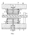
- FIG. 4 shows the device has cutting knives 6 and 7 and cores 8a, 8b and 9a, 9b.
- the Knives 6 and 7 are on the mounting plates head plate 16 and foot plate 17th attached.
- the cores 8a, 8b and 9a, 9b are movable in the cutting knives 6 and 7 out.
- the cores 8a, 8b and 9a, 9b exist in this development from stamps 8a, 9a and from guides 8b and 9b.
- the guides 8b and 9b can be provided in the form of collar screws, for example are screwed in on a thread located in the stamps 8a and 9a are.
- the cores 8a, 8b and 9a, 9b are via springs 10 and 11 with the base plate 17 and the head plate 16 and thus with the knives 6 and 7 connected.
- the springs are already biased, whereby the spring force of the spring 11 on the core 9a, 9b is substantially less than that Spring force of the spring 10 on the core 8a, 8b.
- the device a lifting cam 14 and an adjustable stop 15. To access to receive the guide 9b and the cam 14, the base plate 17 with a Cover plate 21 covered and can be removed if necessary.
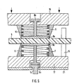
- FIG. 5 shows a first phase of the cutting process.
- This is the headstock 16 pressed with all the parts attached to it in the direction of the footplate 17.
- the cutting knives 6 and 7 cut into those to be cut Plastic 5 a. Since the spring force of the preloaded spring 11 is lower than that of the spring 10 and thus the core 9a, 9b yields rather than the core 8a, 8b, the cutting knife 7 first cuts into the plastic 5.
- the first Cutting knife 7 has already its predetermined in the phase shown in FIG. 5 Depth of penetration reached, since the core 9a, 9b is already indented so far that the guide 9b sits on the lifting cam 14, which acts as a limitation here and the core 9a, 9b is thus rigidly coupled to the cutting knife 7. hereby further penetration of the cutting knife 7 into the plastic 5 prevented.
- Fig. 6 shows a second phase of the cutting process.
- second knife 6 up to its predetermined depth of penetration into the plastic material 5 penetrated.
- the depth of penetration is not like this Cutting knife 7 limited by the core, but by the stop 15, on which the head plate 16 is placed.
- the adjustable stop 15 also serves at the same time as a spacer, which is the end position between the mounting plates Base plate 17 and head plate 16 defines and thus the end position the cutting knife attached to the mounting plates.
- the attack 15 thus ensures that the cutting knife during a Do not touch the cutting process.
- Fig. 7 shows the last phase of the cutting process. This is where the Hubnokke presses 14 after the cutting knives 6 and 7 have reached their end position, the first core 9a, 9b back to its original position. hereby will that still over. a thin core 20 with the remaining plastic 5 connected clippings 5 'broken out. Breaking out the clippings 5 'is only possible here since the second core 8a, 8b has no limitation.
- the lifting cam 14 can also be rigidly connected to the base plate 17 connected limitation are replaced, which then makes the device has no mechanism for breaking out the clippings and thus the phase shown in FIG. 7 is omitted, but the overall construction becomes easier.
- the spring 10 brings the core 8a, 8b back in its original position according to FIG. 4.
- the plastic 5 must be transported by a suitable amount are and the lifting cam 14 are lowered again.
- the particular advantage of this invention 4-7 can be seen in the fact that different thicknesses Plastics 5 can be cut with the device without the device to adjust accordingly, since the end position of the Cutting knife 6 and 7 regardless of the thickness of the plastic 5 by the adjustable stop 15 is set. It changes through that Changing the thickness of the plastic only the location of the burr on the cutting edge.
- FIG. 8 Another device according to the invention is shown in FIG. 8.
- the device also has the Advantage on that the clippings can be cut practically without curvature can, as explained below.
- the device is essentially constructed like the device according to FIG 4-7. It also has two mounting plates head plate 24 and Base plate 25 on which the knives 36 and 37 are attached. In the knives 36 and 37 are also movably guided cores 8a, 8b and 9a, 9b arranged, which are biased by the springs 10 and 11. The spring force the spring 11 is also much smaller than that of the spring 10. Furthermore an adjustable stop 15 is also provided. Beyond that a limitation for the core 9a, 9b is provided, which is not here as in the 4 - 7 movable in the form of a lifting cam 14, but in the form of the cover plate 26 is rigidly provided. Thus, the device cannot do the final cut Break out clippings (see Fig. 7). Of course, it can also the lifting cam 14 shown in Figs. 4-7 are used when the breakout of the finished cut clippings is desired.
- the cutting knives 36 and 37 additional Have cutting edges 28 and 29. These cut when cutting the clippings 5 'additionally a relief cut between the actual Cutting edge of the material to be cut 5 'and the edge of the plastic 5 is achieved that the displaced by the cutting of the knives 36 and 37 Plastic material when cutting the plastic 5 does not cause tension of the clippings and the remaining plastic 5 leads, causing bulges be avoided.
- positioning the one to be cut Plastic over positioning means is towards it make sure that the clippings are cut out sufficiently close to the edge of the plastic is so that the relief cut cut by the cutting edges 28 and 29 actually the edge of the plastic 5 with the cut edge of the clippings 5 'connects.
- Two cutting blades are also provided in the device, in which movable guided cores are provided.
- the cores set similarly to the core 9a, 9b of FIGS. 4-7 on a limit after the cutting of the Cutting knife penetrated into the plastic by the specified penetration depth are, whereby the cores are rigidly coupled to the knives and this further penetrates the cutting knife into the plastic prevent.
- the distance between the cutting knives in the end position is here exactly like in the example shown in Fig.1 by the offset of the cores compared to the cutting edges of the cutting knife.
- the cores can also be exactly like that shown in Figs. 4-7 Example to be connected to the cutting knives via pre-tensioned springs, so that the cores return to their starting position after the cutting process are pressed, the starting position being exactly the same as that shown in FIGS. 4-7 Example is chosen so that the cores essentially with the Complete the cutting knife edge. This can also result in an emission plastic that is stuck in the cutting edge can be guaranteed.
- one or multi-layer data carrier with a plastic body such as ID cards to be cut out of a plastic tape.
- a plastic body such as ID cards to be cut out of a plastic tape.
- the use for data carriers in which an additional is advantageous Electronic module is arranged - so-called chip cards - such as Phone cards.
- the module arranged in the card body includes an integrated circuit and conductive with the integrated Circuit-connected contact areas for communication with external Devices.
- the external dimensions of such data carriers with electronic Modules are usually measured according to ISO standard 7810 and must be observed relatively exactly in order to ensure correct contact to ensure the contact surfaces of the electronic module.
- mini chip cards or plug-in cards which are usually made today a data medium manufactured according to ISO 7810 can be cut out, whereby for the reasons mentioned, these data carriers must also be relatively true to size have to.
- mini chip cards can be particularly advantageous with a 8 are cut.
- One with the said Device-cut mini chip card can be seen in Fig. 9.
- the mini chip card 34 with the electronic module 35 described above is off the card 30 made according to ISO 7810 cut out, the cutting edge 31 via at least one relief cut 33 with the edge of the card body 32 of the original card 30 is connected. Of course he has to said relief cut 33 are not mandatory.
- the mini chip card 34 thus cut preferably remains, which is still over a narrow soul with the remaining card body 32 of the original Card 30 is connected, in the body 32.
- the cutting ridge is still here formed as a narrow soul, the mini chip card with the card body 32 of the original card 30 connects.
- the customer who has such Acquires card 30, the mini chip card 34 prepared in this way can then be used for the first time Break use out of card body 32 manually.
- the one remaining through the use of the device according to the invention Cutting edge on the cutting edges of the data carriers described above is, as far as is still noticeable, between the edges to the surfaces of the disk and preferably in the middle of the Cutting edge.
- the devices are preferably set such that that the cutting edge in a data carrier manufactured in accordance with ISO 7810 located approximately in the middle of the cutting edge.
- the invention is not limited to the embodiments shown in Figures 4-8 limited. So these figures shown only show the purely schematically Structure of possible devices according to the invention, the devices can also be constructed differently.
- the guides 8b and 9b can also be designed such that the Offset of the cores 8a, 8b and 9a, 9b can be changed.
- It is still one Cutting device with cutting blades conceivable in which only one of the Cutting knives or none of the cutting knives limit said cores the depth of penetration.
- the invention also in the 1 additionally a stop, similar to the stop 15, be provided, which determines the end position of the knives 1 and 2. Naturally combined forms are also possible.
Landscapes
- Engineering & Computer Science (AREA)
- Life Sciences & Earth Sciences (AREA)
- Forests & Forestry (AREA)
- Mechanical Engineering (AREA)
- Physics & Mathematics (AREA)
- Microelectronics & Electronic Packaging (AREA)
- Computer Hardware Design (AREA)
- General Physics & Mathematics (AREA)
- Theoretical Computer Science (AREA)
- Processing And Handling Of Plastics And Other Materials For Molding In General (AREA)
- Nonmetal Cutting Devices (AREA)
- Perforating, Stamping-Out Or Severing By Means Other Than Cutting (AREA)
- Details Of Cutting Devices (AREA)
Abstract
Description
Die bekannten Schneidvorrichtungen haben gegenüber herkömmlichen Stanz- bzw. Schneidvorrichtungen, bei denen eine Patrize mit einer Matrize zusammenwirkt, den Vorteil, daß sie im wesentlichen maßhaltiges Schnittgut erzeugen. Die Maßhaltigkeit ist dabei weitestgehend von dem zu schneidenden Kunststoff unabhängig, so daß auch relativ spröde und damit problematisch zu verarbeitende Kunststoffe, wie beispielsweise Polycarbonat, relativ maßhaltig geschnitten werden können. Darüber hinaus können auch unterschiedlichste Kunststoffe mit ein und derselben Schneidvorrichtung bearbeitet werden, ohne Anpassungen an den betreffenden Werkstoff vornehmen zu müssen.
- Fig.1
- eine Schnittzeichnung durch einen Ausschnitt einer nicht erfindungsgemäßen Schneidvorrichtung,
- Fig. 2
- eine Schneidvorrichtung gemäß Fig. 1 mit geschlossenen Messern,
- Fig. 3
- fertiggeschnittenes Schnittgut,
- Fig. 4.
- Enfindungsgemäße Weiterbildung der Schneidvorrichtung gemäß Fig. 1 mit Mitteln zum Ausbrechen des fertiggeschnittenen Schnittguts aus dem verbleibenden Kunststoff,
- Fig. 5
- Schneidvorrichtung nach Fig. 4 mit halbgeschlossenen Messern,
- Fig. 6
- Schneidvorrichtung nach Fig. 4 mit vollständig geschlossenen Messern,
- Fig. 7
- Schneidvorrichtung nach Fig. 4 mit aus dem verbleibenden Kunststoff herausgebrochenen Schnittgut,
- Fig. 8
- Schneidvorrichtung, mit der wölbungsfrei geschnitten werden kann,
- Fig. 9
- Minichipkarte.
Claims (10)
- Vorrichtung zum Schneiden von Kunststoffen mit einem ersten keilförmigen Schneidmesser (6) und mit einem als Gegenlager mit diesem zusammenwirkenden zweiten keilförmigen Schneidmesser (7), die jeweils auf Montageplatten (16, 17) montiert sind, wobei der zu schneidende Kunststoff (5) zwischen erstem und zweitem Schneidmesser (6, 7) angeordnet wird und mit Mitteln, welche den Abstand der Schneidmesser in ihrer Endposition bestimmen, um eine Berührung der Schneidmesser (6,7) während des Schneidvorganges zu verhindern,
dadurch gekennzeichnet, daß
die genannten Mittel einen verstellbaren Anschlag (15) umfassen, der den Abstand zwischen den Montageplatten (16, 17) begrenzt. - Vorrichtung nach Anspruch 1, dadurch gekennzeichnet, dass die genannten Mittel mit den Schneidmessern (6, 7) verbundene und während des Schneidvorganges gegenüber den Schneiden der Schneidmesser (6, 7) zurückversetzte Kerne (8a, 9a) umfassen.
- Vorrichtung nach Anspruch 2, dadurch gekennzeichnet, dass die Kerne (8a, 9a) in den Schneidmessern (6,7) beweglich geführt sind, und dass ein Kern (9a) nach dem Erreichen der vorgegebenen Eindringtiefe des Schneidmessers (7) in den Kunststoff über eine Begrenzung (14) mit dem Schneidmesser (7) starr gekoppelt ist.
- Vorrichtung nach Anspruch 3, dadurch gekennzeichnet, dass die Begrenzung eine Hubnocke (14) ist, die, nachdem sich die Schneidmesser (6, 7) in ihrer Endposition befinden, den mit dem Messer (7) starr gekoppelten Kern (9a) gegen das noch über eine schmale Seele (20) mit dem Kunststoff (5) verbundene Schnittgut (5') presst, wobei dieses aus dem Kunststoff (5) ausgebrochen wird.
- Vorrichtung nach einem der Ansprüche 2, 3 und 4, dadurch gekennzeichnet, dass die Kerne (8a, 9a) zusätzlich über Federn (10, 11) mit den Schneidmessern (6, 7) verbunden sind, so dass die Kerne (8a, 9a) nach dem Schneidvorgang durch die Federn (10, 11) wieder in ihre Ausgangslage gepresst werden, wobei die Ausgangslage derart gewählt ist, dass die Kerne (8a, 9a) im wesentlichen mit der Schneide der Schneidmesser (6, 7) abschließen.
- Vorrichtung nach einem der vorhergehenden Ansprüchen,
dadurch gekennzeichnet, dass der Abstand der Schneidmesser (6,7) in der Endposition zwischen 3 und 50 µm liegt. - Vorrichtung nach einem der vorhergehenden Ansprüchen,
dadurch gekennzeichnet, dass die Schneidmesser (6,7) zusätzliche Schneiden (28, 29) aufweisen, die beim Schneiden des Schnittguts (34) wenigstens einen Entlastungsschnitt (33) vorzugsweise zwischen der Schnittkante (31) des Schnittguts (5'; 34) und dem Rand des Kunststoffes (5; 32) schneiden. - Verfahren zum Schneiden von Schnittgut aus Kunststoffen mit folgenden Verfahrensschritten: .dadurch gekennzeichnet, daßBereitstellen eines Kunststoffes (5),Einrühren des Kunststoffs (5) zwischen zwei Reilförmigen Schneidmesser (6, 7), die jeweils auf Montageplatten montiert sind,Zusammenpressen der Schneidmesser (6,7) unter Verwendung eines Abstandhalters derart, daß der Kunststoff von beiden Seiten geschnitten wird und die Schneidmesser sich nicht berühren,der Abstandhalter einen verstellbaren Anschlag (15) umfäßt, der den Abstand zwischen den Montageplatten (16,17) begrenzt und in Abhängigkeit von dem bereitgestellten Kunststoff (5) derart eingestellt wird, daß die Schneidmesser (6,7) sich beim Zusammenpressen nicht berühren.
- Verfahren nach Anspruch 8, dadurch gekennzeichnet, dass nach dem Schneiden über eine schmale Seele (20) mit dem restlichen Kunststoff (5) verbundenes Schnittgut (5') aus dem Kunststoff (5) ausgebrochen wird.
- Verfahren nach Anspruch 9, dadurch gekennzeichnet, dass das Schnittgut (5') vor dem Öffnen der Schneidmesser (6,7) durch einen im Inneren wenigstens eines Schneidmessers (7) befindlichen Kern (9a) ausgebrochen wird.
Applications Claiming Priority (3)
| Application Number | Priority Date | Filing Date | Title |
|---|---|---|---|
| DE19513282A DE19513282B4 (de) | 1995-04-07 | 1995-04-07 | Vorrichtung und Verfahren zum Schneiden von Kuststoffen sowie nach dem Verfahren hergestellter Datenträger |
| DE19513282 | 1995-04-07 | ||
| PCT/EP1996/001496 WO1996031427A2 (de) | 1995-04-07 | 1996-04-04 | Vorrichtung zum schneiden von kunststoffen |
Publications (2)
| Publication Number | Publication Date |
|---|---|
| EP0773856A2 EP0773856A2 (de) | 1997-05-21 |
| EP0773856B1 true EP0773856B1 (de) | 2004-10-27 |
Family
ID=7759191
Family Applications (1)
| Application Number | Title | Priority Date | Filing Date |
|---|---|---|---|
| EP96914883A Expired - Lifetime EP0773856B1 (de) | 1995-04-07 | 1996-04-04 | Vorrichtung zum schneiden von kunststoffen |
Country Status (8)
| Country | Link |
|---|---|
| EP (1) | EP0773856B1 (de) |
| AR (1) | AR001549A1 (de) |
| AT (1) | ATE280660T1 (de) |
| AU (1) | AU5686396A (de) |
| DE (2) | DE19513282B4 (de) |
| ES (1) | ES2229267T3 (de) |
| MY (1) | MY128751A (de) |
| WO (1) | WO1996031427A2 (de) |
Families Citing this family (23)
| Publication number | Priority date | Publication date | Assignee | Title |
|---|---|---|---|---|
| DE29509736U1 (de) * | 1995-06-14 | 1996-04-04 | Giesecke & Devrient GmbH, 81677 München | Standardkarte mit eingelagerter Minichipkarte |
| EP0849093A1 (de) | 1996-12-18 | 1998-06-24 | Fofitec AG | Formular mit integrierter Karte |
| US6401510B1 (en) | 1999-04-07 | 2002-06-11 | 3M Innovative Properties Company | Method for stamping a part from a multi-layered strip |
| JP2002540949A (ja) * | 1999-04-07 | 2002-12-03 | スリーエム イノベイティブ プロパティズ カンパニー | 多層構造ストリップから部品を打出すための方法および装置 |
| FR2794267B1 (fr) * | 1999-05-27 | 2003-06-20 | Gemplus Card Int | Dispositif portable a circuit integre, de type carte a puce de format reduit par rapport au format standard des cartes a puces et procede de fabrication |
| DE19930439A1 (de) * | 1999-07-01 | 2001-01-11 | Orga Kartensysteme Gmbh | Vorrichtung zur elektrischen Kontaktierung der Kontaktflächen einer auf einer horizontalen Auflagefläche aufliegenden Chipkarte |
| DE10023801C2 (de) * | 2000-05-15 | 2002-05-23 | Giesecke & Devrient Gmbh | Vorrichtung zum Stanzen von Kunststoffen |
| DE10230365B8 (de) * | 2002-07-05 | 2008-09-25 | Mühlbauer Ag | Vorrichtung und Verfahren zum Heraustrennen von Kunststoffkarten |
| DE10317015A1 (de) * | 2003-04-11 | 2004-11-11 | Hans Walter Mohr Gmbh | Vorrichtung zum Stanzen von Werkstücken |
| DE20312000U1 (de) * | 2003-08-02 | 2003-10-02 | Dixi-Comkontec Engineering u. Modellbau GmbH, 99817 Eisenach | Werkzeug zum faserfreien Schneiden von Verkleidungen, Belägen oder ähnlichem |
| ES2391978T3 (es) * | 2006-08-14 | 2012-12-03 | Blumer Maschinenbau Ag | Dispositivo de troquelado y proceso para la operación del mismo |
| CN101823270A (zh) * | 2010-03-15 | 2010-09-08 | 广州东海敏孚汽车部件有限公司 | 一种用于加工汽车饰条的冲切刀具 |
| FR2960819B1 (fr) * | 2010-06-07 | 2012-07-13 | Oberthur Technologies | Procede de fabrication d'un support comportant une carte detachable |
| FR2977518B1 (fr) * | 2011-07-08 | 2013-08-23 | Oberthur Technologies | Lame, procede d'application de pression a une feuille en utilisant ladite lame et support de donnees produit en utilisant ladite lame |
| EP2664424B1 (de) | 2012-05-14 | 2016-01-06 | Oberthur Technologies | Stanzwerkzeug |
| FR3007682B1 (fr) * | 2013-07-01 | 2016-01-08 | Oberthur Technologies | Outillage et procede de fragilisation d'un contour dans une carte plastique mince |
| FR3007681B1 (fr) * | 2013-07-01 | 2015-07-17 | Oberthur Technologies | Fabrication d'une plaque de grande epaisseur comprenant une carte detachable de petite epaisseur |
| GB2527740B (en) * | 2014-05-16 | 2017-04-19 | Burnsides (Marketing Aids) Ltd | Manufacturing method |
| EP3032467A1 (de) * | 2014-12-09 | 2016-06-15 | Gemalto Sa | Verfahren und Vorrichtung zur Herstellung einer Chipkarte, und mit diesem Verfahren erhaltene Chipkarte |
| GB2539381B (en) * | 2015-05-22 | 2017-09-20 | Burnsides (Marketing Aids) Ltd | Manufacturing method |
| ES2730090A1 (es) * | 2018-05-07 | 2019-11-08 | Ind Tecnologicas De Mecanizacion Y Automatizacion S A | Dispositivo de precorte de envases |
| ES2786824B2 (es) | 2019-04-10 | 2021-05-11 | Ind Tecnologicas De Mecanizacion Y Automatizacion S A | Envase multiple y maquina para su fabricacion |
| DE102024111631B3 (de) | 2024-04-25 | 2025-10-02 | Karl Marbach Gmbh & Co. Kg | Stanzwerkzeug und Stanzverfahren für Bögen aus Wabenpappe |
Family Cites Families (7)
| Publication number | Priority date | Publication date | Assignee | Title |
|---|---|---|---|---|
| DE235814C (de) * | ||||
| DE419900C (de) * | 1923-11-01 | 1925-10-12 | August Schieferstein | Werkzeug zum Stanzen und Praegen von Pappschildern |
| US2352339A (en) * | 1942-09-04 | 1944-06-27 | Western Electric Co | Apparatus for blanking materials |
| GB653195A (en) * | 1948-07-13 | 1951-05-09 | Frank Philip Bossom | Making self adhesive labels |
| DE1157466B (de) * | 1961-12-22 | 1963-11-14 | Hermann Bansbach | Schneidwerkzeug zum Schneiden von aufeinandergeschichteten duennen Blaettern |
| DK423583A (da) * | 1983-09-16 | 1985-03-17 | Teknologisk Inst | Fremgangsmaade og vaerktoej til udhugning af huller |
| DE8402745U1 (de) * | 1984-01-31 | 1984-04-26 | Erdmann, Edgar, 8120 Weilheim | Fotografische schneidvorrichtung |
-
1995
- 1995-04-07 DE DE19513282A patent/DE19513282B4/de not_active Expired - Fee Related
-
1996
- 1996-04-03 AR AR33605196A patent/AR001549A1/es unknown
- 1996-04-04 ES ES96914883T patent/ES2229267T3/es not_active Expired - Lifetime
- 1996-04-04 AU AU56863/96A patent/AU5686396A/en not_active Abandoned
- 1996-04-04 WO PCT/EP1996/001496 patent/WO1996031427A2/de not_active Ceased
- 1996-04-04 EP EP96914883A patent/EP0773856B1/de not_active Expired - Lifetime
- 1996-04-04 AT AT96914883T patent/ATE280660T1/de not_active IP Right Cessation
- 1996-04-04 DE DE59611128T patent/DE59611128D1/de not_active Expired - Lifetime
- 1996-04-06 MY MYPI96001321A patent/MY128751A/en unknown
Also Published As
| Publication number | Publication date |
|---|---|
| AR001549A1 (es) | 1997-11-26 |
| DE19513282B4 (de) | 2006-09-14 |
| EP0773856A2 (de) | 1997-05-21 |
| WO1996031427A3 (de) | 1997-01-03 |
| MY128751A (en) | 2007-02-28 |
| DE19513282A1 (de) | 1996-10-10 |
| ES2229267T3 (es) | 2005-04-16 |
| WO1996031427A2 (de) | 1996-10-10 |
| AU5686396A (en) | 1996-10-23 |
| ATE280660T1 (de) | 2004-11-15 |
| DE59611128D1 (de) | 2004-12-02 |
Similar Documents
| Publication | Publication Date | Title |
|---|---|---|
| DE19513282B4 (de) | Vorrichtung und Verfahren zum Schneiden von Kuststoffen sowie nach dem Verfahren hergestellter Datenträger | |
| EP1889696B1 (de) | Stanzvorrichtung und Verfahren zum Betrieb davon | |
| EP0132878B1 (de) | Verfahren und Vorrichtung zur Herstellung einer Düsenplatte für Tintenstrahldrucker | |
| DE69306599T2 (de) | Festsetzvorrichtung für Messer | |
| DE1918780C2 (de) | Verfahren und Vorrichtung zum Feinschneiden von Werkstücken aus Blech | |
| DE69308339T2 (de) | Schneidmesser | |
| CH696194A5 (de) | Verfahren zur Herstellung von Karten aus Kunststoff, Identitätskarte oder Kreditkarte hergestellt nach dem Verfahren und Kartenstanzmaschine zur Durchführung des Verfahrens | |
| EP1285405B1 (de) | Vorrichtung zum stanzen von kunststoffen | |
| DE69710167T2 (de) | Schneidzylinder für Dokumentenvernichter und Verfahren zur Herstellung desselben | |
| EP3509806B1 (de) | Verfahren zur bearbeitung eines substrats mit einem stanzstempel | |
| DE2746725A1 (de) | Schloss fuer eine strickmaschine | |
| DE102009034437A1 (de) | Vorrichtung und Verfahren zur Ausbildung einer Kontur in einem Kartenkörper für einen tragbaren Datenträger, insbesondere für eine Chipkarte | |
| EP0275909B1 (de) | Schneidevorrichtung zum Längsschneiden von Folienbahnen | |
| EP1378330B1 (de) | Vorrichtung und Verfahren zum Heraustrennen von Kunststoffkarten | |
| EP1764194B1 (de) | Stanzvorrichtung und Verfahren zum Betrieb davon | |
| EP1486302A1 (de) | Vorrichtung zum Stanzen von Zuschnitten aus einem Materialbogen | |
| DE102021003336A1 (de) | Verfahren zum Herstellen eines Chipkartenkörpers | |
| DE69930244T2 (de) | Verfahren zum stanzen eines mehrschichtigen streifens | |
| DE2062360A1 (de) | Stanzmaschine | |
| EP2060372A1 (de) | Bürogerät zur Bearbeitung von Blattgut | |
| DE112006001387T5 (de) | Folgeschneidwerkzeugverfahren und -Vorrichtung | |
| DE3016168C2 (de) | Gesamtverbundschneid- und Biegewerkzeug | |
| DE69407016T2 (de) | Klemmvorrichtung für elektrischen Anschluss | |
| DE3905532C1 (en) | Device for destroying data carriers | |
| EP2060371A2 (de) | Bürogerät zum Stanzen von Blattgut |
Legal Events
| Date | Code | Title | Description |
|---|---|---|---|
| PUAI | Public reference made under article 153(3) epc to a published international application that has entered the european phase |
Free format text: ORIGINAL CODE: 0009012 |
|
| 17P | Request for examination filed |
Effective date: 19961205 |
|
| AK | Designated contracting states |
Kind code of ref document: A2 Designated state(s): AT BE CH DE DK ES FI FR GB IT LI SE |
|
| 17Q | First examination report despatched |
Effective date: 20010313 |
|
| GRAP | Despatch of communication of intention to grant a patent |
Free format text: ORIGINAL CODE: EPIDOSNIGR1 |
|
| GRAS | Grant fee paid |
Free format text: ORIGINAL CODE: EPIDOSNIGR3 |
|
| GRAA | (expected) grant |
Free format text: ORIGINAL CODE: 0009210 |
|
| AK | Designated contracting states |
Kind code of ref document: B1 Designated state(s): AT BE CH DE DK ES FI FR GB IT LI SE |
|
| PG25 | Lapsed in a contracting state [announced via postgrant information from national office to epo] |
Ref country code: FI Free format text: LAPSE BECAUSE OF FAILURE TO SUBMIT A TRANSLATION OF THE DESCRIPTION OR TO PAY THE FEE WITHIN THE PRESCRIBED TIME-LIMIT Effective date: 20041027 |
|
| REG | Reference to a national code |
Ref country code: GB Ref legal event code: FG4D Free format text: NOT ENGLISH |
|
| REG | Reference to a national code |
Ref country code: CH Ref legal event code: EP |
|
| REF | Corresponds to: |
Ref document number: 59611128 Country of ref document: DE Date of ref document: 20041202 Kind code of ref document: P |
|
| PG25 | Lapsed in a contracting state [announced via postgrant information from national office to epo] |
Ref country code: SE Free format text: LAPSE BECAUSE OF FAILURE TO SUBMIT A TRANSLATION OF THE DESCRIPTION OR TO PAY THE FEE WITHIN THE PRESCRIBED TIME-LIMIT Effective date: 20050127 Ref country code: DK Free format text: LAPSE BECAUSE OF FAILURE TO SUBMIT A TRANSLATION OF THE DESCRIPTION OR TO PAY THE FEE WITHIN THE PRESCRIBED TIME-LIMIT Effective date: 20050127 |
|
| GBT | Gb: translation of ep patent filed (gb section 77(6)(a)/1977) |
Effective date: 20050209 |
|
| PG25 | Lapsed in a contracting state [announced via postgrant information from national office to epo] |
Ref country code: AT Free format text: LAPSE BECAUSE OF NON-PAYMENT OF DUE FEES Effective date: 20050404 |
|
| REG | Reference to a national code |
Ref country code: ES Ref legal event code: FG2A Ref document number: 2229267 Country of ref document: ES Kind code of ref document: T3 |
|
| PG25 | Lapsed in a contracting state [announced via postgrant information from national office to epo] |
Ref country code: LI Free format text: LAPSE BECAUSE OF NON-PAYMENT OF DUE FEES Effective date: 20050430 Ref country code: CH Free format text: LAPSE BECAUSE OF NON-PAYMENT OF DUE FEES Effective date: 20050430 Ref country code: BE Free format text: LAPSE BECAUSE OF NON-PAYMENT OF DUE FEES Effective date: 20050430 |
|
| ET | Fr: translation filed | ||
| PLBE | No opposition filed within time limit |
Free format text: ORIGINAL CODE: 0009261 |
|
| STAA | Information on the status of an ep patent application or granted ep patent |
Free format text: STATUS: NO OPPOSITION FILED WITHIN TIME LIMIT |
|
| 26N | No opposition filed |
Effective date: 20050728 |
|
| BERE | Be: lapsed |
Owner name: GIESECKE & DEVRIENT G.M.B.H. Effective date: 20050430 |
|
| REG | Reference to a national code |
Ref country code: CH Ref legal event code: PL |
|
| BERE | Be: lapsed |
Owner name: *GIESECKE & DEVRIENT G.M.B.H. Effective date: 20050430 |
|
| PGFP | Annual fee paid to national office [announced via postgrant information from national office to epo] |
Ref country code: GB Payment date: 20110419 Year of fee payment: 16 |
|
| GBPC | Gb: european patent ceased through non-payment of renewal fee |
Effective date: 20120404 |
|
| PG25 | Lapsed in a contracting state [announced via postgrant information from national office to epo] |
Ref country code: GB Free format text: LAPSE BECAUSE OF NON-PAYMENT OF DUE FEES Effective date: 20120404 |
|
| REG | Reference to a national code |
Ref country code: DE Ref legal event code: R082 Ref document number: 59611128 Country of ref document: DE |
|
| PGFP | Annual fee paid to national office [announced via postgrant information from national office to epo] |
Ref country code: DE Payment date: 20140430 Year of fee payment: 19 Ref country code: FR Payment date: 20140416 Year of fee payment: 19 Ref country code: ES Payment date: 20140417 Year of fee payment: 19 Ref country code: IT Payment date: 20140424 Year of fee payment: 19 |
|
| REG | Reference to a national code |
Ref country code: DE Ref legal event code: R119 Ref document number: 59611128 Country of ref document: DE |
|
| PG25 | Lapsed in a contracting state [announced via postgrant information from national office to epo] |
Ref country code: IT Free format text: LAPSE BECAUSE OF NON-PAYMENT OF DUE FEES Effective date: 20150404 Ref country code: DE Free format text: LAPSE BECAUSE OF NON-PAYMENT OF DUE FEES Effective date: 20151103 |
|
| REG | Reference to a national code |
Ref country code: FR Ref legal event code: ST Effective date: 20151231 |
|
| PG25 | Lapsed in a contracting state [announced via postgrant information from national office to epo] |
Ref country code: FR Free format text: LAPSE BECAUSE OF NON-PAYMENT OF DUE FEES Effective date: 20150430 |
|
| REG | Reference to a national code |
Ref country code: ES Ref legal event code: FD2A Effective date: 20160527 |
|
| PG25 | Lapsed in a contracting state [announced via postgrant information from national office to epo] |
Ref country code: ES Free format text: LAPSE BECAUSE OF NON-PAYMENT OF DUE FEES Effective date: 20150405 |