EP0773460A2 - Objectif de prise de vue pour caméra vidéo - Google Patents
Objectif de prise de vue pour caméra vidéo Download PDFInfo
- Publication number
- EP0773460A2 EP0773460A2 EP96308113A EP96308113A EP0773460A2 EP 0773460 A2 EP0773460 A2 EP 0773460A2 EP 96308113 A EP96308113 A EP 96308113A EP 96308113 A EP96308113 A EP 96308113A EP 0773460 A2 EP0773460 A2 EP 0773460A2
- Authority
- EP
- European Patent Office
- Prior art keywords
- lens
- lens group
- negative
- positive
- object side
- Prior art date
- Legal status (The legal status is an assumption and is not a legal conclusion. Google has not performed a legal analysis and makes no representation as to the accuracy of the status listed.)
- Granted
Links
Images


Classifications
-
- G—PHYSICS
- G02—OPTICS
- G02B—OPTICAL ELEMENTS, SYSTEMS OR APPARATUS
- G02B17/00—Systems with reflecting surfaces, with or without refracting elements
- G02B17/02—Catoptric systems, e.g. image erecting and reversing system
- G02B17/04—Catoptric systems, e.g. image erecting and reversing system using prisms only
- G02B17/045—Catoptric systems, e.g. image erecting and reversing system using prisms only having static image erecting or reversing properties only
-
- G—PHYSICS
- G02—OPTICS
- G02B—OPTICAL ELEMENTS, SYSTEMS OR APPARATUS
- G02B15/00—Optical objectives with means for varying the magnification
- G02B15/14—Optical objectives with means for varying the magnification by axial movement of one or more lenses or groups of lenses relative to the image plane for continuously varying the equivalent focal length of the objective
- G02B15/144—Optical objectives with means for varying the magnification by axial movement of one or more lenses or groups of lenses relative to the image plane for continuously varying the equivalent focal length of the objective having four groups only
- G02B15/1441—Optical objectives with means for varying the magnification by axial movement of one or more lenses or groups of lenses relative to the image plane for continuously varying the equivalent focal length of the objective having four groups only the first group being positive
- G02B15/144113—Optical objectives with means for varying the magnification by axial movement of one or more lenses or groups of lenses relative to the image plane for continuously varying the equivalent focal length of the objective having four groups only the first group being positive arranged +-++
-
- G—PHYSICS
- G02—OPTICS
- G02B—OPTICAL ELEMENTS, SYSTEMS OR APPARATUS
- G02B5/00—Optical elements other than lenses
- G02B5/04—Prisms
Definitions
- the present invention is related to optical lenses and, in particular, to image pickup lens systems for video cameras.
- the size of a solid-state image sensing device i.e., a charged-coupled device (CCD)
- CCD charged-coupled device
- Various ways to reduce parts in the lens array are to include an inner focus lens, as disclosed in Japanese Patent Application Laid-Open No. 62-24213 (1987), or an aspherical lens, as disclosed in Japanese Patent Application Laid-Open No. 3-33710 (1991).
- lenses that are components of the image pickup lens system are arranged in a straight line. That is, an optical axis extending from an object side to an image side forms a straight line.
- the miniaturization of a video camera with such a lens arrangement is quite limited, even if other steps for miniaturization have been taken into account.
- the lenses arrayed along a straight line present an obstacle to the overall camera length reduction and impose restrictions on the camera design.
- a zoom lens has been used frequently in the image pickup lens system of the video camera. Since the zoom lens is typically larger than the general lens, the problem of miniaturization is even more pronounced in this case.
- the lenses in a non-linear configuration, i.e., to fold the optical axis of the image pickup lens system so that the lenses are positioned at right angles to each other, for example.
- a mirror is located between a wide-angle converter lens and a master lens (zoom lens) for folding the optical axis of the system.
- the attendant deterioration of the imaging performance has been difficult to solve in these devices due to mass production errors. Since high precision in assembling the lens system is difficult to achieve during mass production, this problem has been greatly exacerbated in image pickup lens systems with non-linear optical axes.
- the wide-angle lens is composed of four groups (positive, negative, positive and positive groups, counting from the object to the image side) and has a field angle of 60 degrees.
- a mirror is positioned between the wide-angle converter lens and the master lens (zoom lens) to fold the optical axis of the image pickup lens system.
- the master lenses would have to be enlarged causing a corresponding increase in the physical size and weight of the camera.
- a reflecting member such as a mirror is added to the zoom lens of the 6-324265 application to fold the optical axis, the lens must be also increased in size to provide the desired zoom function.
- This invention provides an integrated video camera and recording/reproducing apparatus, comprising: a main body including a viewfinder portion, a recording/reproducing portion, and an image pickup lens system having an object side, an image side and an optical axis, said image pickup lens system including a wide angle converter and a zoom lens, wherein said wide angle converter comprises at least a negative lens and a positive lens spaced apart from each other such that D1/D1A is greater than 1.2 and less than 1.7 where D1 is a distance between a lens surface of said negative lens closest to said object side and a lens surface of said positive lens closest to said image side, and D1A is a distance between said negative lens and said positive lens.
- This invention also provides an image pickup lens system for a video camera, comprising: a zoom lens located at an image side of said image pickup lens system, and a wide angle converter located at an object side of said image pickup lens system and optically coupled to said zoom lens, said wide angle converter comprising a first lens group having at least a negative lens group and a positive lens group spaced apart from each other such that D1/D1A is greater than 1.2 and less than 1.7 where D1 is a distance between a lens surface of said first lens group closest to said object side and a lens surface of said first lens group closest to said image side, and D1A is a distance between said negative lens group and said positive lens group.
- Embodiments of the invention can provide a compact video camera with a zooming function and wide angle field of view.
- Embodiments of the invention can provide a video camera with a compact image pickup lens system which has wider tolerances for easier assembly of lenses in the system.
- Embodiments of the invention can provide a video camera with a compact image pickup lens system comprising a zoom lens and a wide-angle converter.
- Embodiments of the invention can provide an image pickup lens system with a zoom lens and a wide-angle converter such that the optical axis of the lens system is folded between its object side and its image side.
- Embodiments of the invention can provide an image pickup lens system with a zoom lens and a wide-angle converter such that the optical axis of the lens system is folded closer to its object side than its image side.
- Embodiments of the invention comprise an integrated video camera and recording/reproducing apparatus having a main body including a viewfinder portion, a recording/reproducing portion, and an image pickup lens system having an object side, an image side and an optical axis.
- the image pickup lens system includes a zoom lens and a wide angle converter.
- the wide angle converter includes at least a negative lens and a positive lens spaced apart from each other such that D1/D1A is greater than 1.2 and less than 1.7 where D1 is a distance between a lens surface of the negative lens closest to the object side and a lens surface of the positive lens closest to the image side, and D1A is a distance between the negative lens and the positive lens.
- the inventive apparatus further includes a reflecting member located between the negative and positive lens with the optical axis folded.
- the optical axis is folded at a position which is closer to the object side than the image side of the apparatus.
- an image pickup lens system for a video camera comprises a zoom lens located at an image side of the image pickup lens system and a wide angle converter located at an object side of the image pickup lens system and optically coupled to the zoom lens.
- the wide angle converter includes a first lens group having at least a negative lens group and a positive lens group spaced apart from each other such that D1/D1A is greater than 1.2 and less than 1.7 where D1 is a distance between a lens surface of the first lens group closest to the object side and a lens surface of the first lens group closest to the image side, and D1A is a distance between the negative lens group and the positive lens group.
- the second lens group is movable between the first and third groups in response to a zooming operation between a wide angle end and a telephoto end of the image pickup lens system.
- the fourth group is movable between the third lens group and the image side for focusing an image as a function of the zooming operation.
- the apparatus further includes a reflecting member, such as a prism or mirror, located between the negative and positive lens groups with the common optical axis folded therebetween.
- the common optical axis is folded, at substantially 90 degrees, at a position which is closer to the object side than the image side of the apparatus.
- FIG. 1A shows video camera 10 having main body 12 which includes three major portions: viewfinder portion 15, recording and reproducing portion 13 and imaging portion 14, also referred to as the image pickup lens system.
- microphone 17 positioned in the front part of the camera, battery storage portion 16 in the rear part of the camera and grip 18 for holding the video camera.
- a tape deck cover swings outward, in the direction indicated by P, such that a recording medium, i.e., cassette, can be inserted into the video camera for recording and reproduction.
- the image pickup lens in the video camera is illustratively represented by a zoom lens.
- each of the zoom lenses 14, 14A and 14B includes a four group structure: the first lens group GR1 has positive refracting power, the second lens group GR2 has negative refracting power, the third lens group GR3 has positive refracting power and the fourth lens group GR4 has also positive refracting power (positive, negative, positive, positive groups.
- a zooming operation is performed by moving at least the second lens group GR2 from the object side to the image side in the lens barrel (not shown).
- at least the fourth lens group GR4 can be moved to obtain a proper focus on image surface 22. That is, the fourth group GR4 compensates for the movement of the second group GR2 as a result of the zooming operation.
- glass block FL functioning as an optical low-pass filter, which is positioned between the fourth lens group GR4 and the image side.
- Diaphragm IR is arranged between the second lens group GR2 and the third lens group GR3.
- the first lens group GR1 functioning as the wide angle converter is formed of a negative lens group NL and a positive lens group PL.
- the positive lens group PL includes at least negative lens 23, positive lens 24 and positive lens 25, as shown in Figs 2A, 4A and 6A.
- conditional expression (1) 1.2 ⁇ D1/D1A ⁇ 1.7
- D1/D1A becomes smaller than 1.2 in the conditional expression (1), the space between the negative lens group NL and the positive lens group PL becomes too wide, thereby diminishing compactness of the design. In addition, in this case the front lens diameter becomes too large and is no longer practical in a compact video camera. Conversely, when the value of D1/D1A exceeds 1.7, the space between the negative lens group NL and the positive lens group PL becomes too narrow. This, in turn, prevents insertion of the reflecting member for folding optical axis X. That is, the space for inserting the prism PR or mirror MR disappears.
- the negative lens group NL of the first lens group GR1 is composed of single element, i.e., negative lens 26, in all three embodiments.
- the positive lens group PL of the first lens group GR1 is composed of four elements instead of three, i.e., positive lens 47, negative lens 23, and positive lenses 24, 25 arranged consecutively from the object side.
- an afocal unit is formed for correcting vibrations or shaking of a camera during the shooting of a video.
- the afocal unit is comprised of negative lens 26 of the first lens group GR1 and of positive lens 47 which follows negative lens 26.
- positive lens 47 may be added on the object side of the lens group PL to the three-piece structure of negative lens 23 and positive lenses 24, 25 to obtain a positive lens group PL of the four-piece structure.
- the afocal unit with the negative lens group NL (negative lens 26) and the additional positive lens 47, it becomes possible to assemble the folding portion of the optical axis X, i.e., the portion on the object side of positive lens 47, independently of other lens groups in the image pickup lens system of the camera. This becomes a significant advantage in mass production since the tolerances for each lens group need not be very strict.
- the optical axis X may be folded in each of the wide-angle zoom lenses 14, 14A and 14B of Figs. 2A, 4A and 6A, respectively, the combined total length of the image pickup lens system becomes longer by the additional space for the prism PR or mirror MR required for folding the optical axis X. To obtain compactness of the video camera, it, therefore, becomes necessary to reduce the total length of the image pickup lens system.
- the second lens group GR2 in order to shorten the total length of the system, it is possible to decrease either the movement of the second lens group GR2 or the distance from the third lens group GR3 to image surface 22. If the movement of the second lens group GR2 is reduced, the magnification power of the second lens group GR2 must be correspondingly increased with the attendant deterioration of the optical performance in the system. Consequently, the second option is more advantageous.
- the distance from the third lens group GR3 to image surface 22 is shortened. This is accomplished by forming the zoom lens in the lens group GR3 with a two-piece structure of positive lens 68 and negative lens 69 arranged consecutively from the object side to the image side. Such arrangement of the third lens group GR3 provides a telephoto lens.
- the third lens group GR3 is structured so that if "R31” is the radius of curvature of positive lens 68 on the object side, and “R32” is the radius of curvature of positive lens 68 on the image side, then the following expression is obtained:
- conditional expression (4) ⁇ D3/fW > 1.2
- conditional expression (5) it confirms that the correction of the chromatic aberration within the third lens group GR3 is made properly. Namely, it is possible to lower the degree of correction of chromatic aberration of the third lens group GR3 by setting the Abbe number of positive lens 68 and negative lens 69 such that the conditional expression (5) is satisfied. As a result, it becomes easier to correct the chromatic aberration of the complete lens system.
- d i shows the space between the ith surface and the (i+1)th surface
- N i " and “ ⁇ ” show the refractive index and the Abbe number, respectively, with respect to the spectral d-line of a medium between the ith surface and the (i+1)th surface.
- the lenses in these embodiments may include aspherical surfaces.
- Xa is a coordinate in the X-direction of the optical axis of the aspherical surface
- c is a paraxial curvature (1/r)
- A is the 2i-th aspherical coefficient
- y is the distance from the optical axis X.
- Figs. 2A, 2B, 2C, 2D, 3A, 3B and 3C pertain to the first embodiment of the present invention.
- Zoom lens 14 in the first embodiment comprises a 4-group, 10-piece structure of the first through the fourth lens groups GR1, GR2, GR3 and GR4 located consecutively from the object side, as shown in Fig. 2A.
- Fig. 2B shows dimensional values for the lenses of the zoom lens 14, where the 18th and the 21st surfaces are aspherical.
- Fig. 2C shows the 4th, 6th and the 8th-order aspherical coefficients A4, A6 and A8, respectively, of these aspherical surfaces, i.e., the 18th and 21st.
- "e" designates an exponential expression with base 10.
- Fig. 2D shows values for d 10 (the space between the first lens group GR1 and the second lens group GR2), d 15 (the space between the second lens group GR2 and the diaphragm IR), d 18 (the space between the third lens group GR3 and the fourth lens group GR4) and d 21 (the space between the fourth lens group GR4 and the glass block FL) when f (the focal length of the whole system) changes from 1.000 to 2.4903 and then to 9.5727 according to the operation of zoom lens 14.
- Figs. 3A, 3B and 3C show a spherical aberration diagram, an astigmatism diagram and a distortion aberration diagram, respectively, in the wide-angle, normal and telephoto states of zoom lens 14.
- a solid line shows values along the spectral d-line
- the solid line shows values on a sagittal image surface
- the dashed line shows values on a meridional image surface.
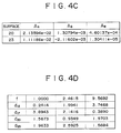
- Figs. 4A, 4B, 4C, 4D, 5A, 5B and 5C pertain to the second embodiment of the present invention.
- Zoom lens 14A in the second embodiment comprises a 4-group, 11-piece structure of the first through the fourth lens groups GR1, GR2, GR3 and GR4 located consecutively from the object side, as shown in Fig. 4A.
- Fig. 4B shows dimensional values for the lenses of the zoom lens 14A, where the 20th and the 23rd surfaces are aspherical.
- Fig. 4C shows the 4th, 6th and the 8th-order aspherical coefficients A4, A6 and A8, respectively, of these aspherical surfaces, i.e., the 20th and 23rd.
- Fig. 4D shows respective values of d 12 (the space between the first lens group GR1 and the second lens group GR2), d 17 (the space between the second lens group GR2 and the diaphragm IR), d 20 (the space between the third lens group GR3 and the fourth lens group GR4) and d 23 (the space between the fourth lens group GR4 and the glass block FL) when f (the focal length of the whole system) changes from 1.000 to 2.4615 and then to 9.5692 according to the operation of zoom lens 14A.
- Fig. 5A, 5B and 5C show the spherical aberration diagram, the astigmatism diagram and the distortion aberration diagram, respectively, in the wide-angle, normal and telephoto states of zoom lens 14A.
- Figs. 6A, 6B, 6C, 6D, 7A, 7B and 7C pertain to the third embodiment of the present invention.
- Zoom lens 14B in the third embodiment comprises a 4-group, 12-piece structure of the first through the fourth lens groups GR1, GR2, GR3 and GR4 located consecutively from the object side, as shown in Fig. 6A.
- Fig. 6B shows dimensional values for the lenses of the zoom lens 14B, where the 3rd, 21st and the 26th surfaces are aspherical.
- Fig. 6C shows the 4th, 6th and the 8th-order aspherical coefficients A4, A6 and A8, respectively, of these aspherical surfaces, i.e., the 3rd, 21st and 26th.
- Fig. 6D shows respective values of d 13 (the space between the first lens group GR1 and the second lens group GR2), d 18 (the space between the second lens group GR2 and the diaphragm IR), d 23 (the space between the third lens group GR3 and the fourth lens group GR4) and d 26 (the space between the fourth lens group GR4 and the glass block FL) when f (the focal length of the whole system) varies between 1.000, 2.4499 and 9.5815 according to the operation of zoom lens 14B.
- Fig. 7A, 7B and 7C show the spherical aberration diagram, the astigmatism diagram and the distortion aberration diagram, respectively, in the wide-angle, normal and telephoto states of zoom lens 14B.
- negative lens 26 of the first lens group GR1 has a composite aspheric surface on the image side. Such surface corrects the distortion aberration and is obtained by having a resin layer glued to a glass spherical surface.
- a compact video camera can be achieved with the image pickup lens system.
- the system provides, among other things, a wide angle field of view combined with a zoom lens. Furthermore, the so-called folding of the optical axis offered by the image pickup lens system contributes to the overall compactness and flexible design of the video camera.
- an afocal unit AU comprises negative lens group NL with negative refracting power and positive lens group PL with positive refracting power.
- Reflecting member PR or MR is arranged between the negative lens group NL and positive lens group PL, as shown in Figs. 9A, 11A and 13A.
- the optical axis X of the image pickup lens system 14C, 14D or 14E is folded at approximately 90 degrees at the surface of the reflecting member PR or MR, extending toward the image side.
- the exemplary fifth embodiment of Fig. 11A shows the mirror MR used as the reflecting member, while the fourth and sixth embodiments of Figs. 9A and 13A, respectively, use the prism PR.
- the afocal unit AU can also operate as the wide-angle converter.
- the afocal unit AU and imaging lens portion FU are composed of the four lens groups GR1, GR2, GR3 and GR4 having positive, negative, positive and positive refracting power, respectfully, located consecutively from the object side.
- the first lens group GR1 and the third lens group GR3 are fixed with respect to image surface 22.
- the second lens group GR2 moves from the object side to the image side within a lens mirror cylinder (not shown), and vice versa.
- the fourth lens group GR4 can be moved to obtain a proper focus on image surface 22 attendant upon the movement of the second lens group GR2.
- a glass block FL functions as an optical low-pass filter, which is positioned between the fourth lens group GR4 and image surface 22.
- Diaphragm IR is arranged between the second lens group GR2 and the third lens group GR3.
- lens surfaces in the fourth, fifth and sixth embodiments are aspherical.
- Xa is the coordinate in the X-direction of the optical axis
- c is the paraxial curvature (1/r)
- A is the 2i-th aspherical coefficient
- y is the distance from the optical axis X.
- the image pickup lens system 14C comprises the afocal unit AU and the imaging portion FU.
- the afocal unit AU is a two-piece lens structure which comprises negative lens group NL and positive lens group PL, located consecutively from the object side, and prism PR which is the reflecting member arranged between the negative lens group NL and positive lens group PL.
- the imaging portion FU following the afocal unit AU comprises a nine-piece lens structure, which together with the afocal unit AU is composed of the first through the fourth lens groups GR1, GR2, GR3 and GR4.
- Fig. 9B shows dimensional values for the lenses in the image pickup lens system 14C in the fourth embodiment.
- the 20th and the 23rd surfaces are aspherical.
- Fig. 9C shows the fourth, the sixth and the eighth aspherical coefficients A4, A6 and A8 of these surfaces.
- Fig. 9D shows the respective values of d12, d17, d20 and d23 when f varies between 1.000, 2.4615 and 9.5692 with the zooming operation of the image pickup lens system 14C proceeding from the wide angle end to the telephoto end.
- Figs. 10A, 10B and 10C show the spherical aberration diagram, the astigmatism diagram and the distortion aberration diagram, respectively, in the wide-angle, normal and telephoto states of zoom lens 14C.
- image pickup lens system 14D comprises the afocal unit AU and the imaging portion FU.
- the afocal unit AU is a two-group, two-piece lens structure which is composed of a negative lens group NL and a positive lens group PL located consecutively from the object side, and a mirror MR which is the reflecting member arranged between the negative lens group NL and positive lens group PL.
- the imaging portion FU following the afocal unit AU comprise a four-group, nine-piece lens structure.
- the afocal unit AU and imaging portion FU are composed of the first through the fourth lens groups GR1, GR2, GR3 and GR4.
- Fig. 11B shows dimensional values for the lenses in the image pickup lens system 14D in the fifth embodiment.
- the 18th and the 21st surfaces are aspherical.
- Fig. 11C shows the fourth, the sixth and the eighth aspherical coefficients A4, A6 and A8 of these surfaces.
- Fig. 11D shows the respective values of d 10 , d 15 , d 18 and d 21 when f varies between 1.000, 2.4863 and 9.5741 with the zooming operation of the image pickup lens system 14D proceeding from the wide angle end to the telephoto end.
- Fig. 12A, 12B and 12C show the spherical aberration diagram, the astigmatism diagram and a distortion aberration diagram, respectively, in the wide-angle, normal and telephoto states of zoom lens 14C.
- the image pickup lens system 14E comprises the afocal unit AU and the imaging portion FU.
- the afocal unit AU is a two-piece lens structure which is composed of a negative lens group NL and a positive lens group PL, consecutively located from the object side.
- a prism PR is positioned between the negative lens group NL and positive lens group PL.
- the imaging lens portion FU following the afocal unit AU comprises a ten-piece lens structure, which together with the afocal unit AU, is composed of the first through the fourth lens groups GR1, GR2, GR3 and GR4.
- Fig. 13B shows dimensional values for the lenses in the image pickup lens system 14E in the sixth embodiment.
- the 3rd, 21st and the 26th surfaces are aspherical.
- Fig. 13C shows the fourth, the sixth and the eighth aspherical coefficients A4, A6 and A8 of these aspherical surfaces.
- Fig. 14D shows the respective values of d13, d18, d23 and d26 when f varies between 1.000, 2.4499 and 9.5812 with the zooming operation of the image pickup lens system 14E proceeding from the wide angle end to the telephoto end.
- Figs. 14A, 14B and 14C show the spherical aberration diagram, the astigmatism diagram and the distortion aberration diagram, respectively, in the wide-angle, normal and telephoto states of zoom lens 14E.
- the negative lens NL which is closest to the object side has a composite aspheric surface on the image side.
- Such surface corrects the distortion aberration and is obtained by having a resin layer glued to a glass spherical surface.
- a prism or mirror is provided as the reflecting member.
- the prism preferably should be made of a glass material with a relatively high refractive index. Since the overall optical path length may be shortened by using such a glass material in the prism, it is possible to decrease the front lens diameter. Furthermore, since total reflection can be utilized, a reflecting film is not required in the system, while the reflectivity can be even increased compared with constructors that use a reflecting film. Hence, a cost-saving advantage is achieved.
- the afocal unit AU when the afocal unit AU functions as the wide-angle converter, large negative distortion aberration may be generated by the negative lens group NL.
- the aspherical surface may be any of a glass aspherical surface, a plastic aspherical surface or a composite aspherical surface obtained by having a resin layer glued to a glass spherical lens.
- each of the negative lens group NL and the positive lens group PL of the afocal unit AU is formed from a single lens, the film thickness of the respective lens groups NL and PL can be thin. Thus, miniaturization of the camera, in combination with low cost of the image pickup lens system, can be realized.
- a conventional lens structure of the afocal unit AU may become quite complex, causing an increase in size and cost.
- chromatic aberration which cannot be corrected fully in the afocal unit AU, is additionally corrected in the imaging portion FU according to the present invention, the above-mentioned possible disadvantages of increased cost and size are completely eliminated.
- the image pickup lens system comprises an afocal unit and an imaging portion, consecutively located from the object side, and a reflecting member positioned between the negative and positive lens groups that form the afocal unit, such that an optical axis from the object side and an optical axis at an image surface is folded by the reflecting member.
- the reflecting member is arranged in such a way that the position where the optical axis is folded is located closer to the object side.
- the tolerance becomes larger for placement accuracy during the assembly of the afocal unit and the imaging portion, reducing degradation in optical performance due to possible errors during production.
- it is easier to allocate the space closer to the object side for folding the optical axis.
Landscapes
- Physics & Mathematics (AREA)
- General Physics & Mathematics (AREA)
- Optics & Photonics (AREA)
- Lenses (AREA)
Applications Claiming Priority (6)
| Application Number | Priority Date | Filing Date | Title |
|---|---|---|---|
| JP31579995 | 1995-11-10 | ||
| JP315799/95 | 1995-11-10 | ||
| JP7315799A JPH09133858A (ja) | 1995-11-10 | 1995-11-10 | 撮像レンズ系 |
| JP318570/95 | 1995-11-13 | ||
| JP31857095A JP3789532B2 (ja) | 1995-11-13 | 1995-11-13 | 撮像レンズ系 |
| JP31857095 | 1995-11-13 |
Publications (3)
| Publication Number | Publication Date |
|---|---|
| EP0773460A2 true EP0773460A2 (fr) | 1997-05-14 |
| EP0773460A3 EP0773460A3 (fr) | 1998-07-15 |
| EP0773460B1 EP0773460B1 (fr) | 2003-03-26 |
Family
ID=26568427
Family Applications (1)
| Application Number | Title | Priority Date | Filing Date |
|---|---|---|---|
| EP96308113A Expired - Lifetime EP0773460B1 (fr) | 1995-11-10 | 1996-11-08 | Objectif de prise de vue pour caméra vidéo |
Country Status (4)
| Country | Link |
|---|---|
| US (1) | US6104432A (fr) |
| EP (1) | EP0773460B1 (fr) |
| KR (1) | KR100424961B1 (fr) |
| DE (1) | DE69626930T2 (fr) |
Cited By (8)
| Publication number | Priority date | Publication date | Assignee | Title |
|---|---|---|---|---|
| EP0967506A2 (fr) * | 1998-06-22 | 1999-12-29 | Canon Kabushiki Kaisha | Objectif à focale variable |
| EP1353208A1 (fr) * | 2002-04-10 | 2003-10-15 | Olympus Optical Co., Ltd. | Objective à focale variable et système d'imagerie électronique l'utilisant |
| WO2003085438A1 (fr) * | 2002-04-05 | 2003-10-16 | Olympus Corporation | Objectif zoom et appareil de mise en image dans lequel il est utilise |
| WO2003085439A1 (fr) | 2002-04-09 | 2003-10-16 | Olympus Corporation | Objectif zoom et appareil de formation d'image dans lequel il est utilise |
| WO2004066011A1 (fr) * | 2003-01-17 | 2004-08-05 | Sony Corporation | Objectif zoom et appareil a tube analyseur |
| EP1628152A2 (fr) * | 2002-05-14 | 2006-02-22 | Olympus Corporation | Lentille de zoom et appareil d'imagerie électronique comportant cette lentille |
| EP1666945A1 (fr) * | 2003-09-08 | 2006-06-07 | Sony Corporation | Objectif a focale variable et dispositif d'imagerie |
| EP1748310A2 (fr) * | 2005-07-27 | 2007-01-31 | Sony Corporation | Objectif d'imagerie et appareil d'imagerie |
Families Citing this family (28)
| Publication number | Priority date | Publication date | Assignee | Title |
|---|---|---|---|---|
| JP3564014B2 (ja) * | 1999-09-28 | 2004-09-08 | キヤノン株式会社 | 防振機能を有したズームレンズ及びそれを有するテレビカメラ |
| US7006141B1 (en) * | 1999-11-23 | 2006-02-28 | Panavision, Inc. | Method and objective lens for spectrally modifying light for an electronic camera |
| US7436599B2 (en) | 2001-05-14 | 2008-10-14 | Olympus Corporation | Electronic image pickup system |
| JP4103392B2 (ja) * | 2002-01-08 | 2008-06-18 | コニカミノルタオプト株式会社 | 撮像装置 |
| US7177094B2 (en) * | 2002-04-05 | 2007-02-13 | Olympus Corporation | Zoom lens, and electronic imaging system using the same |
| JP4145066B2 (ja) * | 2002-04-09 | 2008-09-03 | オリンパス株式会社 | ズームレンズとそれを用いた電子撮像装置 |
| JP2004037927A (ja) | 2002-07-04 | 2004-02-05 | Minolta Co Ltd | 撮像装置 |
| US20060044423A1 (en) * | 2002-07-04 | 2006-03-02 | Hitoshi Hagimori | Package/container for batteries |
| JP2004037926A (ja) * | 2002-07-04 | 2004-02-05 | Minolta Co Ltd | 撮像装置 |
| JP3864897B2 (ja) * | 2002-12-02 | 2007-01-10 | コニカミノルタフォトイメージング株式会社 | 撮像レンズ装置 |
| JP2004037924A (ja) * | 2002-07-04 | 2004-02-05 | Minolta Co Ltd | 撮像装置 |
| JP4103475B2 (ja) * | 2002-07-05 | 2008-06-18 | コニカミノルタオプト株式会社 | 撮像レンズ装置 |
| JP2004170707A (ja) * | 2002-11-20 | 2004-06-17 | Minolta Co Ltd | 撮像レンズ装置およびそれを備えたデジタルカメラ |
| JP3925457B2 (ja) * | 2003-05-06 | 2007-06-06 | コニカミノルタフォトイメージング株式会社 | 撮影装置 |
| JP3896988B2 (ja) * | 2003-05-12 | 2007-03-22 | コニカミノルタフォトイメージング株式会社 | 撮像レンズ装置 |
| JP3750672B2 (ja) * | 2003-05-20 | 2006-03-01 | コニカミノルタフォトイメージング株式会社 | 撮像レンズ装置 |
| JP4222165B2 (ja) * | 2003-09-08 | 2009-02-12 | ソニー株式会社 | ズームレンズおよび撮像装置 |
| JP4477336B2 (ja) * | 2003-10-15 | 2010-06-09 | オリンパス株式会社 | ズームレンズ及びそれを用いた電子撮像装置 |
| JP2006098686A (ja) * | 2004-09-29 | 2006-04-13 | Olympus Corp | ズームレンズ及びそれを用いた電子撮像装置 |
| JP4681842B2 (ja) * | 2004-09-30 | 2011-05-11 | キヤノン株式会社 | ズームレンズ及びそれを有する撮像装置 |
| US20060187322A1 (en) * | 2005-02-18 | 2006-08-24 | Janson Wilbert F Jr | Digital camera using multiple fixed focal length lenses and multiple image sensors to provide an extended zoom range |
| US7256944B2 (en) * | 2005-02-18 | 2007-08-14 | Eastman Kodak Company | Compact image capture assembly using multiple lenses and image sensors to provide an extended zoom range |
| EP1888653B1 (fr) * | 2005-06-07 | 2016-01-13 | Saudi Basic Industries Corporation | Procede pour la polymerisation d'olefines |
| JP4839788B2 (ja) * | 2005-11-15 | 2011-12-21 | コニカミノルタオプト株式会社 | 撮像光学系および撮像装置 |
| KR101271733B1 (ko) * | 2011-02-11 | 2013-06-04 | 삼성테크윈 주식회사 | 줌 렌즈계 |
| KR102253997B1 (ko) | 2015-08-13 | 2021-05-20 | 코어포토닉스 리미티드 | 비디오 지원 및 스위칭/비스위칭 동적 제어 기능이 있는 듀얼-애퍼처 줌 카메라 |
| CN115857135A (zh) | 2017-02-23 | 2023-03-28 | 核心光电有限公司 | 折叠式摄影机透镜设计 |
| CN108632536B (zh) * | 2018-07-31 | 2020-10-30 | Oppo广东移动通信有限公司 | 一种相机控制方法及装置、终端、存储介质 |
Citations (5)
| Publication number | Priority date | Publication date | Assignee | Title |
|---|---|---|---|---|
| US3658411A (en) * | 1970-09-08 | 1972-04-25 | Eastman Kodak Co | Folded path zoom lens |
| JPH035714A (ja) * | 1989-06-01 | 1991-01-11 | Canon Inc | ワイドコンバーターレンズ |
| JPH0455808A (ja) * | 1990-06-25 | 1992-02-24 | Fuji Photo Film Co Ltd | コンバージョンレンズ装置 |
| JPH0470616A (ja) * | 1990-07-06 | 1992-03-05 | Canon Inc | ワイドコンバーターレンズ |
| JPH07104218A (ja) * | 1993-10-08 | 1995-04-21 | Canon Inc | 変倍光学系 |
Family Cites Families (5)
| Publication number | Priority date | Publication date | Assignee | Title |
|---|---|---|---|---|
| GB1523492A (en) * | 1974-12-28 | 1978-09-06 | Nippon Kogaku Kk | Zoom lens system |
| JPS5651709A (en) * | 1979-10-03 | 1981-05-09 | Minolta Camera Co Ltd | Reverse telephoto type wide angle lens |
| GB2240637B (en) * | 1989-11-21 | 1994-05-11 | Asahi Optical Co Ltd | Zoom lens system for use with a compact camera having a wide coverage of angles |
| JP2921163B2 (ja) * | 1991-04-08 | 1999-07-19 | キヤノン株式会社 | 光学的ローパスフィルターを有した撮像装置 |
| US5530594A (en) * | 1993-08-31 | 1996-06-25 | Nikon Corporation | Zoom lens |
-
1996
- 1996-11-07 US US08/745,056 patent/US6104432A/en not_active Expired - Lifetime
- 1996-11-08 KR KR1019960053575A patent/KR100424961B1/ko not_active IP Right Cessation
- 1996-11-08 DE DE69626930T patent/DE69626930T2/de not_active Expired - Lifetime
- 1996-11-08 EP EP96308113A patent/EP0773460B1/fr not_active Expired - Lifetime
Patent Citations (5)
| Publication number | Priority date | Publication date | Assignee | Title |
|---|---|---|---|---|
| US3658411A (en) * | 1970-09-08 | 1972-04-25 | Eastman Kodak Co | Folded path zoom lens |
| JPH035714A (ja) * | 1989-06-01 | 1991-01-11 | Canon Inc | ワイドコンバーターレンズ |
| JPH0455808A (ja) * | 1990-06-25 | 1992-02-24 | Fuji Photo Film Co Ltd | コンバージョンレンズ装置 |
| JPH0470616A (ja) * | 1990-07-06 | 1992-03-05 | Canon Inc | ワイドコンバーターレンズ |
| JPH07104218A (ja) * | 1993-10-08 | 1995-04-21 | Canon Inc | 変倍光学系 |
Non-Patent Citations (4)
| Title |
|---|
| PATENT ABSTRACTS OF JAPAN vol. 015, no. 115 (P-1181), 19 March 1991 -& JP 03 005714 A (CANON INC), 11 January 1991, * |
| PATENT ABSTRACTS OF JAPAN vol. 016, no. 247 (P-1365), 5 June 1992 -& JP 04 055808 A (FUJI PHOTO FILM CO LTD), 24 February 1992, * |
| PATENT ABSTRACTS OF JAPAN vol. 016, no. 272 (P-1373), 18 June 1992 -& JP 04 070616 A (CANON INC), 5 March 1992, * |
| PATENT ABSTRACTS OF JAPAN vol. 095, no. 007, 31 August 1995 -& JP 07 104218 A (CANON INC), 21 April 1995, * |
Cited By (27)
| Publication number | Priority date | Publication date | Assignee | Title |
|---|---|---|---|---|
| EP0967506A2 (fr) * | 1998-06-22 | 1999-12-29 | Canon Kabushiki Kaisha | Objectif à focale variable |
| EP0967506A3 (fr) * | 1998-06-22 | 2000-12-06 | Canon Kabushiki Kaisha | Objectif à focale variable |
| WO2003085438A1 (fr) * | 2002-04-05 | 2003-10-16 | Olympus Corporation | Objectif zoom et appareil de mise en image dans lequel il est utilise |
| WO2003085439A1 (fr) | 2002-04-09 | 2003-10-16 | Olympus Corporation | Objectif zoom et appareil de formation d'image dans lequel il est utilise |
| EP2226667A1 (fr) * | 2002-04-09 | 2010-09-08 | Olympus Corporation | Objectif de zoom et système d'imagerie électronique l'utilisant |
| EP1494054A1 (fr) * | 2002-04-09 | 2005-01-05 | Olympus Corporation | Objectif zoom et appareil de formation d'image dans lequel il est utilise |
| EP2226669A1 (fr) * | 2002-04-09 | 2010-09-08 | Olympus Corporation | Objectif de zoom et système d'imagerie électronique l'utilisant |
| EP2226668A1 (fr) * | 2002-04-09 | 2010-09-08 | Olympus Corporation | Objectif de zoom et système d'imagerie électronique l'utilisant |
| EP1494054A4 (fr) * | 2002-04-09 | 2009-01-07 | Olympus Corp | Objectif zoom et appareil de formation d'image dans lequel il est utilise |
| EP1353208A1 (fr) * | 2002-04-10 | 2003-10-15 | Olympus Optical Co., Ltd. | Objective à focale variable et système d'imagerie électronique l'utilisant |
| US6865026B2 (en) | 2002-04-10 | 2005-03-08 | Olympus Corporation | Zoom lens, and electronic imaging system using the same |
| US7085070B2 (en) | 2002-05-14 | 2006-08-01 | Olympus Corporation | Zoom lens and electronic imaging device having the same |
| EP1628152A3 (fr) * | 2002-05-14 | 2006-05-24 | Olympus Corporation | Lentille de zoom et appareil d'imagerie électronique comportant cette lentille |
| EP1628152A2 (fr) * | 2002-05-14 | 2006-02-22 | Olympus Corporation | Lentille de zoom et appareil d'imagerie électronique comportant cette lentille |
| US7215486B2 (en) | 2002-05-14 | 2007-05-08 | Olympus Optical Co., Ltd | Zoom lens and electronic imaging device having the same |
| EP1363152B1 (fr) * | 2002-05-14 | 2006-03-01 | Olympus Corporation | Lentille de zoom et appareil d'imagerie électronique comportant cette lentille |
| US7782542B2 (en) | 2002-05-14 | 2010-08-24 | Olympus Corporation | Zoom lens and electronic imaging device having the same |
| US7486446B2 (en) | 2002-05-14 | 2009-02-03 | Olympus Corporation | Zoom lens and electronic imaging device having the same |
| US7463427B2 (en) | 2003-01-17 | 2008-12-09 | Sony Corporation | Zoom lens and image pickup apparatus |
| WO2004066011A1 (fr) * | 2003-01-17 | 2004-08-05 | Sony Corporation | Objectif zoom et appareil a tube analyseur |
| EP1666945A1 (fr) * | 2003-09-08 | 2006-06-07 | Sony Corporation | Objectif a focale variable et dispositif d'imagerie |
| US7433131B2 (en) | 2003-09-08 | 2008-10-07 | Sony Corporation | Zoom lens and imaging apparatus |
| EP1666945A4 (fr) * | 2003-09-08 | 2008-01-16 | Sony Corp | Objectif a focale variable et dispositif d'imagerie |
| EP1748310A3 (fr) * | 2005-07-27 | 2007-08-01 | Sony Corporation | Objectif d'imagerie et appareil d'imagerie |
| EP1748310A2 (fr) * | 2005-07-27 | 2007-01-31 | Sony Corporation | Objectif d'imagerie et appareil d'imagerie |
| US7809256B2 (en) | 2005-07-27 | 2010-10-05 | Sony Corporation | Imaging lens device and imaging apparatus |
| US8009972B2 (en) | 2005-07-27 | 2011-08-30 | Sony Corporation | Imaging lens device and imaging apparatus |
Also Published As
| Publication number | Publication date |
|---|---|
| KR100424961B1 (ko) | 2004-07-19 |
| EP0773460A3 (fr) | 1998-07-15 |
| DE69626930D1 (de) | 2003-04-30 |
| US6104432A (en) | 2000-08-15 |
| DE69626930T2 (de) | 2004-03-04 |
| EP0773460B1 (fr) | 2003-03-26 |
Similar Documents
| Publication | Publication Date | Title |
|---|---|---|
| US6104432A (en) | Compact image pickup lens system for a video camera | |
| US6606194B2 (en) | Variable magnification optical system having image stabilizing function | |
| US7212351B2 (en) | Zoom optical system and image taking apparatus using the same | |
| US7453642B2 (en) | Zoom lens system and image pickup apparatus having the same | |
| JP3570253B2 (ja) | ズームレンズ | |
| US7206139B2 (en) | Zoom lens system and lens barrel having the same | |
| JP4817699B2 (ja) | ズームレンズ及びそれを有する撮像装置 | |
| JP4929903B2 (ja) | ズームレンズ、撮像装置、ズームレンズの変倍方法 | |
| JP4980772B2 (ja) | ズームレンズおよび撮像装置 | |
| US6010537A (en) | Zoom lens system having an image blur compensation function | |
| US7791817B2 (en) | Electronic image pickup apparatus | |
| US6266189B1 (en) | Zoom lens system having an image blur compensating function | |
| US20070242367A1 (en) | Zoom lens system and image pickup apparatus including the same | |
| JPH09133858A (ja) | 撮像レンズ系 | |
| JP2006220715A (ja) | ズームレンズ及びそれを用いた撮像装置 | |
| JP2010107566A (ja) | 撮像装置 | |
| JP4035328B2 (ja) | 変倍光学系及びそれを用いた光学機器 | |
| JP4674567B2 (ja) | ズームレンズとこれを具備する光学装置 | |
| JP3331011B2 (ja) | 小型の2群ズームレンズ | |
| JP5750640B2 (ja) | ズームレンズ及びそれを備える撮像装置 | |
| JP3518472B2 (ja) | ズームレンズ | |
| JP4379957B2 (ja) | リアフォーカス式ズームレンズ及びそれを用いた光学機器 | |
| JP3245469B2 (ja) | 2群ズームレンズ | |
| JP2000321498A (ja) | ズームレンズ系 | |
| JP3789532B2 (ja) | 撮像レンズ系 |
Legal Events
| Date | Code | Title | Description |
|---|---|---|---|
| PUAI | Public reference made under article 153(3) epc to a published international application that has entered the european phase |
Free format text: ORIGINAL CODE: 0009012 |
|
| AK | Designated contracting states |
Kind code of ref document: A2 Designated state(s): DE FR GB |
|
| PUAL | Search report despatched |
Free format text: ORIGINAL CODE: 0009013 |
|
| AK | Designated contracting states |
Kind code of ref document: A3 Designated state(s): DE FR GB |
|
| RHK1 | Main classification (correction) |
Ipc: G02B 15/16 |
|
| 17P | Request for examination filed |
Effective date: 19981204 |
|
| 17Q | First examination report despatched |
Effective date: 20010705 |
|
| GRAH | Despatch of communication of intention to grant a patent |
Free format text: ORIGINAL CODE: EPIDOS IGRA |
|
| GRAH | Despatch of communication of intention to grant a patent |
Free format text: ORIGINAL CODE: EPIDOS IGRA |
|
| GRAA | (expected) grant |
Free format text: ORIGINAL CODE: 0009210 |
|
| AK | Designated contracting states |
Designated state(s): DE FR GB |
|
| REG | Reference to a national code |
Ref country code: GB Ref legal event code: FG4D |
|
| REF | Corresponds to: |
Ref document number: 69626930 Country of ref document: DE Date of ref document: 20030430 Kind code of ref document: P |
|
| ET | Fr: translation filed | ||
| PLBE | No opposition filed within time limit |
Free format text: ORIGINAL CODE: 0009261 |
|
| STAA | Information on the status of an ep patent application or granted ep patent |
Free format text: STATUS: NO OPPOSITION FILED WITHIN TIME LIMIT |
|
| 26N | No opposition filed |
Effective date: 20031230 |
|
| REG | Reference to a national code |
Ref country code: GB Ref legal event code: 746 Effective date: 20091130 |
|
| PGFP | Annual fee paid to national office [announced via postgrant information from national office to epo] |
Ref country code: FR Payment date: 20121130 Year of fee payment: 17 Ref country code: DE Payment date: 20121121 Year of fee payment: 17 |
|
| PGFP | Annual fee paid to national office [announced via postgrant information from national office to epo] |
Ref country code: GB Payment date: 20121120 Year of fee payment: 17 |
|
| GBPC | Gb: european patent ceased through non-payment of renewal fee |
Effective date: 20131108 |
|
| REG | Reference to a national code |
Ref country code: FR Ref legal event code: ST Effective date: 20140731 |
|
| REG | Reference to a national code |
Ref country code: DE Ref legal event code: R119 Ref document number: 69626930 Country of ref document: DE Effective date: 20140603 |
|
| PG25 | Lapsed in a contracting state [announced via postgrant information from national office to epo] |
Ref country code: DE Free format text: LAPSE BECAUSE OF NON-PAYMENT OF DUE FEES Effective date: 20140603 |
|
| PG25 | Lapsed in a contracting state [announced via postgrant information from national office to epo] |
Ref country code: GB Free format text: LAPSE BECAUSE OF NON-PAYMENT OF DUE FEES Effective date: 20131108 Ref country code: FR Free format text: LAPSE BECAUSE OF NON-PAYMENT OF DUE FEES Effective date: 20131202 |