EP0772025A1 - Procédé de détection de phase, pour un système de détection de position - Google Patents
Procédé de détection de phase, pour un système de détection de position Download PDFInfo
- Publication number
- EP0772025A1 EP0772025A1 EP96117223A EP96117223A EP0772025A1 EP 0772025 A1 EP0772025 A1 EP 0772025A1 EP 96117223 A EP96117223 A EP 96117223A EP 96117223 A EP96117223 A EP 96117223A EP 0772025 A1 EP0772025 A1 EP 0772025A1
- Authority
- EP
- European Patent Office
- Prior art keywords
- electric
- phase
- signal
- detected
- data
- Prior art date
- Legal status (The legal status is an assumption and is not a legal conclusion. Google has not performed a legal analysis and makes no representation as to the accuracy of the status listed.)
- Granted
Links
Images

Classifications
-
- G—PHYSICS
- G01—MEASURING; TESTING
- G01D—MEASURING NOT SPECIALLY ADAPTED FOR A SPECIFIC VARIABLE; ARRANGEMENTS FOR MEASURING TWO OR MORE VARIABLES NOT COVERED IN A SINGLE OTHER SUBCLASS; TARIFF METERING APPARATUS; MEASURING OR TESTING NOT OTHERWISE PROVIDED FOR
- G01D5/00—Mechanical means for transferring the output of a sensing member; Means for converting the output of a sensing member to another variable where the form or nature of the sensing member does not constrain the means for converting; Transducers not specially adapted for a specific variable
- G01D5/12—Mechanical means for transferring the output of a sensing member; Means for converting the output of a sensing member to another variable where the form or nature of the sensing member does not constrain the means for converting; Transducers not specially adapted for a specific variable using electric or magnetic means
- G01D5/14—Mechanical means for transferring the output of a sensing member; Means for converting the output of a sensing member to another variable where the form or nature of the sensing member does not constrain the means for converting; Transducers not specially adapted for a specific variable using electric or magnetic means influencing the magnitude of a current or voltage
- G01D5/20—Mechanical means for transferring the output of a sensing member; Means for converting the output of a sensing member to another variable where the form or nature of the sensing member does not constrain the means for converting; Transducers not specially adapted for a specific variable using electric or magnetic means influencing the magnitude of a current or voltage by varying inductance, e.g. by a movable armature
- G01D5/204—Mechanical means for transferring the output of a sensing member; Means for converting the output of a sensing member to another variable where the form or nature of the sensing member does not constrain the means for converting; Transducers not specially adapted for a specific variable using electric or magnetic means influencing the magnitude of a current or voltage by varying inductance, e.g. by a movable armature by influencing the mutual induction between two or more coils
- G01D5/2073—Mechanical means for transferring the output of a sensing member; Means for converting the output of a sensing member to another variable where the form or nature of the sensing member does not constrain the means for converting; Transducers not specially adapted for a specific variable using electric or magnetic means influencing the magnitude of a current or voltage by varying inductance, e.g. by a movable armature by influencing the mutual induction between two or more coils by movement of a single coil with respect to two or more coils
-
- H—ELECTRICITY
- H03—ELECTRONIC CIRCUITRY
- H03M—CODING; DECODING; CODE CONVERSION IN GENERAL
- H03M1/00—Analogue/digital conversion; Digital/analogue conversion
- H03M1/12—Analogue/digital converters
- H03M1/64—Analogue/digital converters with intermediate conversion to phase of sinusoidal or similar periodical signals
- H03M1/645—Analogue/digital converters with intermediate conversion to phase of sinusoidal or similar periodical signals for position encoding, e.g. using resolvers or synchros
Definitions
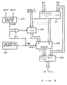
- Multiplier 5 multiplies the sine phase output signal " sin ⁇ ⁇ sin ⁇ t " from the sensor section 1 by the cosine value cos ⁇ from the sine/cosine generation circuit 4, to thereby obtain " cos ⁇ ⁇ sin ⁇ ⁇ sin ⁇ t ".
- Another multiplier 6 multiplies the cosine phase output signal " cos ⁇ ⁇ sin ⁇ t " from the sensor section 1 by the sine value sin ⁇ from the sine/cosine generation circuit 4, to thereby obtain " sin ⁇ ⁇ cos ⁇ ⁇ sin ⁇ t ".
- Subtracter 7 calculates a difference between the output signals of the multipliers 5 and 6, and in response to the output of the subtracter 7, the phase generating operation of the sequential phase generation circuit 3 is controlled as follows.
- the output signal of the secondary winding becomes sin( ⁇ t ⁇ d - ⁇ ) due to the phase variation amount " ⁇ d" based on the non-positional factors (other than the position-to-be-detected) such as temperature change, so that a zero phase point detected by the zero-cross detection circuit 11 would differ by " ⁇ d” from a normal zero phase point in the case of sin( ⁇ t - ⁇ ) .
- the present invention provides a phase difference detection device for position detection which comprises an input section for receiving first and second A.C. output signals from a position sensor (10), the position sensor (10) generating the first A.C. output signal ( sin ⁇ ⁇ sin ⁇ t ) having been amplitude-modulated using, as an amplitude coefficient, a first function value ( sin ⁇ ) corresponding to a position-to-be-detected (x) and generating the second A.C.
- the position sensor (10) for generating the A.C. output signals ( sin ⁇ ⁇ sin ⁇ t and cos ⁇ ⁇ sin ⁇ t ) amplitude-modulated by two different function values in correspondence to the position-to-be-detected (x) is a known sensor such as a resolver.
- the present invention is characterized in that output signals from such a known position sensor (10) (i.e., output signals to which phase-modulation corresponding to the position-to-be-detected has not been applied) is input to the device for detection of a phase difference thereof so that an absolute position can be detected on the basis of the phase difference detection.
- the phase variation " ⁇ d” is cancelled out so that it is allowed to obtain only phase difference data (2 ⁇ ) proportional to a static electric phase angle ( ⁇ ) corresponding to the position-to-be-detected (x).
- This phase difference data (2 ⁇ ) may be used directly as detection data proportional to the position-to-be-detected (x).
- an electric phase angle ( ⁇ ) averaged in half may be obtained for use as the detection data proportional to the position-to-be-detected (x).
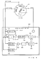
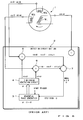
- a single-phase exciting A.C. signal (denoted by " -cos ⁇ t " for convenience of description) generated in a detection circuit section 11 is applied to the position sensor 10 so as to excite the primary winding W1.
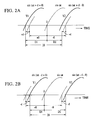
- A.C. output signals are induced in the two-phase secondary windings W2s and W2c in response to excitation of the primary winding W1, and the respective induced voltage levels of the signals present two-phase functional characteristics, sin ⁇ and cos ⁇ , corresponding to a particular position to be detected (position-to-be-detected) x.
- the above-mentioned output signals Y1 and Y2 of the adder and subtracter circuits 15 and 16 are given to zero-cross detection circuits 17 and 18 for detection of the respective zero-cross points of the signals Y1 and Y2.
- the zero-cross detection is done by, for example, identifying a point where the signal Y1 or Y2 changes from a negative value to a positive value, i.e., a zero phase point.
- Zero-cross detection pulses generated by the circuits 17 and 18 upon detection of the respective zero-cross points are applied as latch pulses LP1 and LP2 to corresponding latch circuits 19 and 20.
- the subtracter circuit 22 can obtain only the data ⁇ ( ⁇ (t) in the case where the position x is time-varying) which accurately corresponds only to the position x and from which the phase variation error " ⁇ d" has been eliminated.
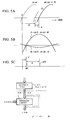
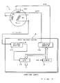
- First and second A.C. output signals A and B are introduced into a detection circuit section 40.
- Fig. 4 is designed to eliminate the phase variation error " ⁇ d" by, on the basis of the first and second output signals A and B output from the position sensor 10, forming the reference phase to be used for measuring the phase difference amount ⁇ in such a manner that the reference phase itself contains the error " ⁇ d".
Applications Claiming Priority (2)
| Application Number | Priority Date | Filing Date | Title |
|---|---|---|---|
| US08/550,358 US5710509A (en) | 1995-10-30 | 1995-10-30 | Phase difference detection device for an inductive position detector |
| US550358 | 1995-10-30 |
Publications (2)
| Publication Number | Publication Date |
|---|---|
| EP0772025A1 true EP0772025A1 (fr) | 1997-05-07 |
| EP0772025B1 EP0772025B1 (fr) | 2005-04-27 |
Family
ID=24196835
Family Applications (1)
| Application Number | Title | Priority Date | Filing Date |
|---|---|---|---|
| EP96117223A Expired - Lifetime EP0772025B1 (fr) | 1995-10-30 | 1996-10-26 | Dispositif et procédé de détection de phase, pour un système de détection de position |
Country Status (4)
| Country | Link |
|---|---|
| US (1) | US5710509A (fr) |
| EP (1) | EP0772025B1 (fr) |
| JP (1) | JP4138899B2 (fr) |
| DE (1) | DE69634656T2 (fr) |
Cited By (10)
| Publication number | Priority date | Publication date | Assignee | Title |
|---|---|---|---|---|
| FR2825147A1 (fr) * | 2001-05-22 | 2002-11-29 | Mitsubishi Electric Corp | Appareil de detection de position et appareil de detection d'anomalie |
| WO2003100353A1 (fr) | 2002-05-29 | 2003-12-04 | Toyoda Koki Kabushiki Kaisha | Detecteur d'angle de rotation et son procede de correction de temperature |
| US7196604B2 (en) | 2001-05-30 | 2007-03-27 | Tt Electronics Technology Limited | Sensing apparatus and method |
| US7205775B2 (en) | 2003-02-17 | 2007-04-17 | Sensopad Limited | Sensing apparatus and method |
| US7298137B2 (en) | 2002-10-16 | 2007-11-20 | Tt Electronics Technology Limited | Position sensing apparatus and method |
| US7319319B2 (en) | 2001-10-30 | 2008-01-15 | Tt Electronics Technology Limited | Sensing apparatus and method |
| US7514919B2 (en) | 2002-10-16 | 2009-04-07 | Tt Electronics Technology Limited | Sensing apparatus and method |
| WO2012107144A1 (fr) * | 2011-02-08 | 2012-08-16 | Robert Bosch Gmbh | Procédé de diagnostic par puce résolveur, dispositif de diagnostic par puce résolveur et produit de programme informatique |
| EP2840701A3 (fr) * | 2013-08-02 | 2015-07-15 | Hamilton Sundstrand Corporation | Détection de position de machine électrique PM |
| DE102017100762B4 (de) * | 2016-01-26 | 2020-08-20 | GM Global Technology Operations LLC | Winkelgeber-phasenausgleich |
Families Citing this family (31)
| Publication number | Priority date | Publication date | Assignee | Title |
|---|---|---|---|---|
| US6552666B1 (en) * | 1996-03-16 | 2003-04-22 | Atsutoshi Goto | Phase difference detection device and method for a position detector |
| JP3170449B2 (ja) * | 1996-03-25 | 2001-05-28 | オークマ株式会社 | アブソリュートエンコーダ |
| JP3368837B2 (ja) * | 1998-08-05 | 2003-01-20 | トヨタ自動車株式会社 | レゾルバ信号処理装置 |
| DE19849554C1 (de) * | 1998-10-27 | 2000-03-02 | Ruf Electronics Gmbh | Verfahren und Vorrichtung zur Bestimmung der Absolutposition bei Weg- und Winkelgebern |
| EP1037017B1 (fr) | 1999-03-15 | 2003-12-17 | Atsutoshi Goto | Capteur inductif de position |
| US6512360B1 (en) * | 1999-03-15 | 2003-01-28 | Amiteq Co., Ltd | Self-induction-type stroke sensor |
| JP4355395B2 (ja) * | 1999-05-19 | 2009-10-28 | 株式会社アミテック | 位置検出データ生成方法及び装置 |
| DE19937737C2 (de) * | 1999-08-10 | 2003-10-30 | Pilz Gmbh & Co | Vorrichtung zum sicheren Überwachen der Drehbewegung einer Welle |
| JP4601789B2 (ja) * | 2000-09-11 | 2010-12-22 | 株式会社アミテック | 位置検出データ生成方法及び装置 |
| JP2003235285A (ja) * | 2002-02-08 | 2003-08-22 | Denso Corp | 三相ブラシレスdcモータの回転方向検出装置 |
| EP1516409B1 (fr) * | 2002-04-03 | 2007-12-12 | Borealis Technical Limited | Machine electrique tournante a ordre de phase eleve comportant des enroulements repartis |
| JP3847656B2 (ja) * | 2002-04-25 | 2006-11-22 | 株式会社ジェイテクト | 角度検出装置における温度検出方法、角度検出装置及び角度検出装置を備えたアクチュエータ制御システム |
| JP4156271B2 (ja) | 2002-05-16 | 2008-09-24 | 株式会社アミテック | パワーステアリング装置用制御ユニット |
| JP4007197B2 (ja) | 2003-01-16 | 2007-11-14 | トヨタ自動車株式会社 | モータ制御装置 |
| JP2005037305A (ja) * | 2003-07-17 | 2005-02-10 | Sanyo Denki Co Ltd | レゾルバの検出位置補正方法及び装置 |
| JP4269278B2 (ja) * | 2004-02-02 | 2009-05-27 | 株式会社デンソー | ブラシレスモータの回転トルク方向検出装置 |
| JP4627746B2 (ja) | 2005-07-19 | 2011-02-09 | 日立オートモティブシステムズ株式会社 | 位相検出回路及びこれを用いたレゾルバ/デジタル変換器並びに制御システム |
| JP4979352B2 (ja) * | 2006-02-28 | 2012-07-18 | 日立オートモティブシステムズ株式会社 | レゾルバ/デジタル変換器及び該レゾルバ/デジタル変換器を用いた制御システム |
| JP4926637B2 (ja) * | 2006-10-05 | 2012-05-09 | 新光電機株式会社 | 変位センサ |
| JP4991322B2 (ja) * | 2006-10-30 | 2012-08-01 | 日立オートモティブシステムズ株式会社 | Gmr素子を用いた変位センサ,gmr素子を用いた角度検出センサ及びそれらに用いる半導体装置 |
| JP5148394B2 (ja) * | 2008-07-11 | 2013-02-20 | 株式会社東芝 | マイクロコンピュータ,モータ制御システム |
| DE102009019509B4 (de) * | 2009-04-24 | 2011-06-09 | Lenze Automation Gmbh | Verfahren und Vorrichtung zum Bestimmen eines Rotorwinkels einer rotierenden Welle |
| JP5237210B2 (ja) * | 2009-06-26 | 2013-07-17 | 株式会社アミテック | 位置検出装置 |
| JP5341832B2 (ja) * | 2010-07-08 | 2013-11-13 | 愛三工業株式会社 | 回転位置センサ |
| US8829840B2 (en) * | 2011-04-29 | 2014-09-09 | General Electric Company | Auto-compensating system and method for condition monitoring of electrical machines |
| US9103847B2 (en) * | 2012-08-01 | 2015-08-11 | Freescale Semiconductor, Inc. | Variable reluctance sensor interface with integration based arming threshold |
| JP6550793B2 (ja) * | 2015-02-27 | 2019-07-31 | 株式会社ジェイテクト | 温度検出装置及び回転角検出装置 |
| US10408643B2 (en) * | 2016-08-18 | 2019-09-10 | Texas Instruments Incorporated | Methods and apparatus to increase resolver-to-digital converter accuracy |
| WO2019155592A1 (fr) * | 2018-02-09 | 2019-08-15 | 株式会社島津製作所 | Détecteur de conductivité électrique et procédé de détermination d'une valeur de réglage de phase d'un signal de soustraction d'arrière-plan |
| WO2021237603A1 (fr) | 2020-05-28 | 2021-12-02 | 华为数字能源技术有限公司 | Procédé de déclenchement d'échantillonnage, microprocesseur, dispositif de commande de moteur, et véhicule électrique |
| WO2023147014A1 (fr) * | 2022-01-27 | 2023-08-03 | Microchip Technology Incorporated | Étalonnage de mésappariements de bobine sinus-cosinus dans des capteurs inductifs |
Citations (3)
| Publication number | Priority date | Publication date | Assignee | Title |
|---|---|---|---|---|
| GB1304377A (fr) * | 1969-03-10 | 1973-01-24 | ||
| US3851330A (en) * | 1973-02-20 | 1974-11-26 | Trw Inc | Amplitude-to-phase conversion circuit |
| EP0738046A1 (fr) * | 1995-04-10 | 1996-10-16 | Tamagawa Seiki Kabushiki Kaisha | Système numérique de détection d'angle |
Family Cites Families (10)
| Publication number | Priority date | Publication date | Assignee | Title |
|---|---|---|---|---|
| GB1120342A (en) * | 1964-12-11 | 1968-07-17 | Plessey Uk Ltd | Improvements relating to synchros and the like |
| US3584783A (en) * | 1967-12-20 | 1971-06-15 | Kaijo Denki Kk | Vector synthesizer for continuously obtaining the magnitude and direction of a vector from the orthogonal components of the vector |
| GB1298669A (en) * | 1969-04-16 | 1972-12-06 | British Aircraft Corp Ltd | Improvements in apparatus for signalling angular displacement |
| US4011440A (en) * | 1975-04-29 | 1977-03-08 | General Electric Company | System for generating an angular rate signal from an angular position signal utilizing a constant amplitude-variable carrier phase signal |
| US4039946A (en) * | 1976-03-18 | 1977-08-02 | The United States Of America As Represented By The Administrator Of The National Aeronautics And Space Administration | Tachometer |
| US4297698A (en) * | 1977-11-02 | 1981-10-27 | Pneumo Corporation | 360 Degree linear variable phase transformer |
| US4612503A (en) * | 1980-10-21 | 1986-09-16 | Kabushiki Kaisha S G | Rotation speed detection device having a rotation angle detector of inductive type |
| US4468617A (en) * | 1982-02-11 | 1984-08-28 | General Electric Company | Velocity sensor and method of producing a velocity signal |
| US4468618A (en) * | 1982-10-28 | 1984-08-28 | Siemens Aktiengesellschaft | System for generating a speed-proportional voltage |
| US5066911A (en) * | 1989-04-07 | 1991-11-19 | Sundstrand Data Control, Inc. | Apparatus and method for sensing displacement using variations magnetic flux linkage |
-
1995
- 1995-10-30 US US08/550,358 patent/US5710509A/en not_active Expired - Lifetime
-
1996
- 1996-10-24 JP JP29978196A patent/JP4138899B2/ja not_active Expired - Lifetime
- 1996-10-26 DE DE69634656T patent/DE69634656T2/de not_active Expired - Lifetime
- 1996-10-26 EP EP96117223A patent/EP0772025B1/fr not_active Expired - Lifetime
Patent Citations (3)
| Publication number | Priority date | Publication date | Assignee | Title |
|---|---|---|---|---|
| GB1304377A (fr) * | 1969-03-10 | 1973-01-24 | ||
| US3851330A (en) * | 1973-02-20 | 1974-11-26 | Trw Inc | Amplitude-to-phase conversion circuit |
| EP0738046A1 (fr) * | 1995-04-10 | 1996-10-16 | Tamagawa Seiki Kabushiki Kaisha | Système numérique de détection d'angle |
Cited By (14)
| Publication number | Priority date | Publication date | Assignee | Title |
|---|---|---|---|---|
| FR2825147A1 (fr) * | 2001-05-22 | 2002-11-29 | Mitsubishi Electric Corp | Appareil de detection de position et appareil de detection d'anomalie |
| US7196604B2 (en) | 2001-05-30 | 2007-03-27 | Tt Electronics Technology Limited | Sensing apparatus and method |
| US7319319B2 (en) | 2001-10-30 | 2008-01-15 | Tt Electronics Technology Limited | Sensing apparatus and method |
| WO2003100353A1 (fr) | 2002-05-29 | 2003-12-04 | Toyoda Koki Kabushiki Kaisha | Detecteur d'angle de rotation et son procede de correction de temperature |
| EP1508783A1 (fr) * | 2002-05-29 | 2005-02-23 | Toyoda Koki Kabushiki Kaisha | Detecteur d'angle de rotation et son procede de correction de temperature |
| EP1508783A4 (fr) * | 2002-05-29 | 2005-12-28 | Toyoda Machine Works Ltd | Detecteur d'angle de rotation et son procede de correction de temperature |
| US7138795B2 (en) | 2002-05-29 | 2006-11-21 | Toyoda Koki Kabushiki Kaisha | Rotation angle detector and its temperature correcting method |
| US7514919B2 (en) | 2002-10-16 | 2009-04-07 | Tt Electronics Technology Limited | Sensing apparatus and method |
| US7298137B2 (en) | 2002-10-16 | 2007-11-20 | Tt Electronics Technology Limited | Position sensing apparatus and method |
| US7205775B2 (en) | 2003-02-17 | 2007-04-17 | Sensopad Limited | Sensing apparatus and method |
| WO2012107144A1 (fr) * | 2011-02-08 | 2012-08-16 | Robert Bosch Gmbh | Procédé de diagnostic par puce résolveur, dispositif de diagnostic par puce résolveur et produit de programme informatique |
| EP2840701A3 (fr) * | 2013-08-02 | 2015-07-15 | Hamilton Sundstrand Corporation | Détection de position de machine électrique PM |
| US9225225B2 (en) | 2013-08-02 | 2015-12-29 | Hamilton Sundstrand Corporation | Sensing PM electrical machine position |
| DE102017100762B4 (de) * | 2016-01-26 | 2020-08-20 | GM Global Technology Operations LLC | Winkelgeber-phasenausgleich |
Also Published As
| Publication number | Publication date |
|---|---|
| DE69634656D1 (de) | 2005-06-02 |
| JP4138899B2 (ja) | 2008-08-27 |
| DE69634656T2 (de) | 2006-03-02 |
| JPH09126809A (ja) | 1997-05-16 |
| US5710509A (en) | 1998-01-20 |
| EP0772025B1 (fr) | 2005-04-27 |
Similar Documents
| Publication | Publication Date | Title |
|---|---|---|
| EP0772025B1 (fr) | Dispositif et procédé de détection de phase, pour un système de détection de position | |
| EP0599175B1 (fr) | Appareil d'interpolation pour une échelle graduée | |
| EP0874223A1 (fr) | Circuit d'interpolation de codeur | |
| JP5173962B2 (ja) | レゾルバ/デジタル変換装置およびレゾルバ/デジタル変換方法 | |
| EP0331189B1 (fr) | Méthode et dispositif de détection de position et/ou vitesse | |
| US6552666B1 (en) | Phase difference detection device and method for a position detector | |
| US4795954A (en) | Resolver controlling method and apparatus | |
| JP3624458B2 (ja) | ディジタル角度検出方法 | |
| JP2005283165A (ja) | バリアブルリラクタンスレゾルバとそれを用いた回転角度センサ | |
| KR101175962B1 (ko) | 리졸버를 이용해 각위치를 결정하기 위한 방법 및 장치 | |
| US6484120B1 (en) | Position detection data generating method and apparatus based on phase shift principle | |
| KR910003518B1 (ko) | 싱크로 전기기계를 이용한 회전검출장치 | |
| JP2009288241A6 (ja) | 第1の事象と第2の事象との間の時間差を求める方法 | |
| JP3920896B2 (ja) | リニア位置検出装置 | |
| JP4048207B2 (ja) | 位置検出装置 | |
| JP3092100B2 (ja) | 誤差補正機能付き位置検出装置 | |
| JP3733400B2 (ja) | 傾斜計 | |
| JP3439814B2 (ja) | デジタルpll装置 | |
| JPH063443Y2 (ja) | オープンループ制御装置 | |
| JPH0781878B2 (ja) | 回転検出装置 | |
| JP2865219B2 (ja) | レゾルバを用いた位置検出装置 | |
| JPH0342766B2 (fr) | ||
| JPH0419512A (ja) | 回転角度検出装置 | |
| JPH10176925A (ja) | 傾斜検出装置 | |
| JP2002090182A (ja) | 位置検出データ生成方法及び装置 |
Legal Events
| Date | Code | Title | Description |
|---|---|---|---|
| PUAI | Public reference made under article 153(3) epc to a published international application that has entered the european phase |
Free format text: ORIGINAL CODE: 0009012 |
|
| 17P | Request for examination filed |
Effective date: 19961026 |
|
| AK | Designated contracting states |
Kind code of ref document: A1 Designated state(s): DE FR GB |
|
| 17Q | First examination report despatched |
Effective date: 20030804 |
|
| GRAP | Despatch of communication of intention to grant a patent |
Free format text: ORIGINAL CODE: EPIDOSNIGR1 |
|
| RTI1 | Title (correction) |
Free format text: DEVICE AND METHOD FOR PHASE DETECTION, FOR USE IN A POSITION DETECTION SYSTEM |
|
| GRAS | Grant fee paid |
Free format text: ORIGINAL CODE: EPIDOSNIGR3 |
|
| GRAA | (expected) grant |
Free format text: ORIGINAL CODE: 0009210 |
|
| AK | Designated contracting states |
Kind code of ref document: B1 Designated state(s): DE FR GB |
|
| REG | Reference to a national code |
Ref country code: GB Ref legal event code: FG4D |
|
| REF | Corresponds to: |
Ref document number: 69634656 Country of ref document: DE Date of ref document: 20050602 Kind code of ref document: P |
|
| ET | Fr: translation filed | ||
| PLBE | No opposition filed within time limit |
Free format text: ORIGINAL CODE: 0009261 |
|
| STAA | Information on the status of an ep patent application or granted ep patent |
Free format text: STATUS: NO OPPOSITION FILED WITHIN TIME LIMIT |
|
| 26N | No opposition filed |
Effective date: 20060130 |
|
| REG | Reference to a national code |
Ref country code: DE Ref legal event code: R082 Ref document number: 69634656 Country of ref document: DE Representative=s name: VON KREISLER SELTING WERNER, DE |
|
| REG | Reference to a national code |
Ref country code: GB Ref legal event code: 732E Free format text: REGISTERED BETWEEN 20140327 AND 20140402 |
|
| REG | Reference to a national code |
Ref country code: DE Ref legal event code: R082 Ref document number: 69634656 Country of ref document: DE Representative=s name: DOMPATENT VON KREISLER SELTING WERNER - PARTNE, DE Effective date: 20140318 Ref country code: DE Ref legal event code: R082 Ref document number: 69634656 Country of ref document: DE Representative=s name: VON KREISLER SELTING WERNER - PARTNERSCHAFT VO, DE Effective date: 20140318 Ref country code: DE Ref legal event code: R081 Ref document number: 69634656 Country of ref document: DE Owner name: AMITEQ CO., LTD., HACHIOJI-SHI, JP Free format text: FORMER OWNER: GOTO, ATSUTOSHI, FUCHU, TOKIO/TOKYO, JP Effective date: 20140318 Ref country code: DE Ref legal event code: R081 Ref document number: 69634656 Country of ref document: DE Owner name: AMITEQ CO., LTD., JP Free format text: FORMER OWNER: GOTO, ATSUTOSHI, FUCHU, JP Effective date: 20140318 |
|
| REG | Reference to a national code |
Ref country code: FR Ref legal event code: TP Owner name: AMITEQ CO., LTD., JP Effective date: 20140401 |
|
| REG | Reference to a national code |
Ref country code: FR Ref legal event code: PLFP Year of fee payment: 20 |
|
| PGFP | Annual fee paid to national office [announced via postgrant information from national office to epo] |
Ref country code: DE Payment date: 20151124 Year of fee payment: 20 Ref country code: GB Payment date: 20151026 Year of fee payment: 20 |
|
| PGFP | Annual fee paid to national office [announced via postgrant information from national office to epo] |
Ref country code: FR Payment date: 20151026 Year of fee payment: 20 |
|
| REG | Reference to a national code |
Ref country code: DE Ref legal event code: R071 Ref document number: 69634656 Country of ref document: DE |
|
| REG | Reference to a national code |
Ref country code: GB Ref legal event code: PE20 Expiry date: 20161025 |
|
| PG25 | Lapsed in a contracting state [announced via postgrant information from national office to epo] |
Ref country code: GB Free format text: LAPSE BECAUSE OF EXPIRATION OF PROTECTION Effective date: 20161025 |