EP0770737A1 - Elément de coffrage - Google Patents
Elément de coffrage Download PDFInfo
- Publication number
- EP0770737A1 EP0770737A1 EP96810677A EP96810677A EP0770737A1 EP 0770737 A1 EP0770737 A1 EP 0770737A1 EP 96810677 A EP96810677 A EP 96810677A EP 96810677 A EP96810677 A EP 96810677A EP 0770737 A1 EP0770737 A1 EP 0770737A1
- Authority
- EP
- European Patent Office
- Prior art keywords
- insulation plate
- formwork element
- angles
- element according
- recess
- Prior art date
- Legal status (The legal status is an assumption and is not a legal conclusion. Google has not performed a legal analysis and makes no representation as to the accuracy of the status listed.)
- Withdrawn
Links
Images
Classifications
-
- E—FIXED CONSTRUCTIONS
- E04—BUILDING
- E04B—GENERAL BUILDING CONSTRUCTIONS; WALLS, e.g. PARTITIONS; ROOFS; FLOORS; CEILINGS; INSULATION OR OTHER PROTECTION OF BUILDINGS
- E04B5/00—Floors; Floor construction with regard to insulation; Connections specially adapted therefor
- E04B5/16—Load-carrying floor structures wholly or partly cast or similarly formed in situ
- E04B5/32—Floor structures wholly cast in situ with or without form units or reinforcements
-
- E—FIXED CONSTRUCTIONS
- E04—BUILDING
- E04G—SCAFFOLDING; FORMS; SHUTTERING; BUILDING IMPLEMENTS OR AIDS, OR THEIR USE; HANDLING BUILDING MATERIALS ON THE SITE; REPAIRING, BREAKING-UP OR OTHER WORK ON EXISTING BUILDINGS
- E04G11/00—Forms, shutterings, or falsework for making walls, floors, ceilings, or roofs
- E04G11/36—Forms, shutterings, or falsework for making walls, floors, ceilings, or roofs for floors, ceilings, or roofs of plane or curved surfaces end formpanels for floor shutterings
- E04G11/365—Stop-end shutterings
-
- E—FIXED CONSTRUCTIONS
- E04—BUILDING
- E04B—GENERAL BUILDING CONSTRUCTIONS; WALLS, e.g. PARTITIONS; ROOFS; FLOORS; CEILINGS; INSULATION OR OTHER PROTECTION OF BUILDINGS
- E04B5/00—Floors; Floor construction with regard to insulation; Connections specially adapted therefor
- E04B5/16—Load-carrying floor structures wholly or partly cast or similarly formed in situ
- E04B5/32—Floor structures wholly cast in situ with or without form units or reinforcements
- E04B2005/322—Floor structures wholly cast in situ with or without form units or reinforcements with permanent forms for the floor edges
Definitions
- the present invention relates to a formwork element according to the preamble of claim 1.
- Formwork elements serve as terminations, separations or connections of floor slabs to be concreted opposite or with other components, for example with masonry. In order to prevent sound or thermal bridges, such formwork elements are provided with insulation material. These formwork elements generally serve at the same time as face formwork or insulation formwork.
- Such formwork elements consist of several angles and an insulation plate connected to the angles.
- the angles can be made of iron as well as plastic. They generally have two legs of different lengths, perpendicular to each other, the longer legs of which, when installed, come to rest on or in the floor slab. They are preferably attached to the floor slab or to its casing.
- the longer legs are provided with bores or slots into which fastening elements such as nails or nail pins can be inserted.
- the longer legs have spacing elements on their lower side facing the formwork of the floor slab.
- An insulation plate running parallel to these is fastened to the shorter legs, wherein the legs can rest directly on an outer surface of the insulation plate or are fixed at a distance from it.
- the insulation plate is attached to the shorter legs by means of thorns which have a widened head.
- the shorter legs each have a hole for receiving the thorn pin. Since the mandrels must be driven through the insulation plate from the side facing away from the legs, it is relatively difficult to hit the corresponding hole in the shorter leg. It is therefore not possible to make such connections directly on the construction site.
- the formwork element according to the invention has the advantage that it can be put together directly on the construction site.
- the individual insulation plates can be stacked, with the respective angles being able to be packed together to form a package with each insulation plate, the angles simply being placed on the insulation plate. They are less damaged and take up less space during storage and transportation.
- the insulation plates are simply plugged onto one leg of the angle, their height with respect to the fastening surface of the angle can be adjusted as desired.
- construction tolerances can thus be compensated for by pressing the insulation plate lower than the lower height of the floor slab so that it comes to rest entirely or almost on the mostly tolerant lower retaining wall.
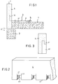
- FIG. 1 shows a connection of a floor slab 1 to a retaining wall 2 by means of a formwork element (3, 4) according to the invention, which thus forms the insulation formwork.
- a formwork element 3, 4
- FIG. 1 shows a connection of a floor slab 1 to a retaining wall 2 by means of a formwork element (3, 4) according to the invention, which thus forms the insulation formwork.
- a single-walled retaining wall is shown, the use of the formwork element according to the invention is not restricted to this. For example, it can also serve as a connection to a double-layer masonry.
- the installation of the formwork element depends on the respective connection partner and is well known.
- the element designated by the reference number 1 can represent both the formwork and the lower structure of the floor slab to which the formwork element is attached, whereupon the effective floor slab is then concreted on.
- the formwork element according to the invention comprises a plurality of angles 3 with legs 30, 31 which are at least approximately perpendicular to one another and an insulation plate 4 which can be fastened thereon.
- the insulation plate 4 can, if it is used, for example, only as thermal insulation, be made of polystyrene or Sagex®. But it can also consist of a filigree plate. All insulation materials are therefore possible, not just foamed materials.
- angle 3 can be used as angle 3. These preferably have a long leg 31 and a short leg 30, the long leg 31 coming to rest on or in the floor cover plate 1 in the installed state.
- the long leg 31 is preferably attached to the floor slab or to its casing.
- the long legs 31 have spacing elements on their lower side facing the cladding of the floor slab, so that they can be arranged at a distance from their bearing surface.
- fastening elements 5 such as nails or nail pins can be inserted.
- the fastening elements 5 are driven into the support surface, that is to say into the floor cover plate 1 or its casing, and thus fix the angles 3 and thus the formwork element.
- To stabilize the long as well as the short legs of the angles can be connected to each other with cross struts.
- the short leg 30 projects above the floor slab 1, but this depends on the corresponding connection partners.
- the insulation plate 4 can be plugged onto these short legs 30 of the associated angles 3. One of these angles 3 is visible in FIG.
- the insulation plate has recesses 40, as can be seen in FIGS. 2 and 3.
- These recesses 40 preferably have the shape of a stepped fold, so that there is a nose 41 partially covering the recess 40.
- the nose 41 is surrounded on both sides, viewed from the front view, by a slot 42 which extends into the cavity formed by the recess 40 and which extends to the end of the recess covered by the nose.
- These recesses 40 can already be made in the insulation plates in the manufacturing plant.
- the recesses should be dimensioned such that their width and / or depth is equal to or smaller than the legs of the associated angles to be inserted.
- the height of the recess corresponds to the length of the short legs 30 of the angles.
- the depth of the recess 40 corresponds approximately to half the thickness of the insulation plate 4.
- the recesses 40 can be aligned with the lower edge 43 of the insulation plate 4. However, they can also be introduced into the insulation plate 4 at a distance from this lower edge.
- these recesses 40 serve to accommodate the short legs 30 of the angles 3.
- the angles 3 must be tilted at an angle relative to the insulation plate, so that the short legs 30 are inserted past the nose 41 into the recess 40 can. Since the mass of the recess 40 is equal to or smaller than that of the short leg 30, the short leg 30 is held fixed therein. Introducing the Leg 30 is facilitated by the light, generally existing elasticity of the insulation material.
- the exact shape of the recess depends on the shape of the associated angle. Angles are known which have a vertically protruding edge on both sides along their legs. The recess described here is very well suited for these angles, since the edge also clamps itself in the recess, whereby it does not impair the tensioning force in the region of the nose 41 due to the slots 42 on both sides, since it projects outwards through these slots 42.
- the height of the recess is dimensioned such that it has the desired height in relation to the contact surface on which the angle is mounted when the leg is inserted completely up to the upper stop of the recess.
- restraint means can already be formed in the recess itself.
- angles are first attached to the support surface, in this case the floor cover plate, and only then the insulation plate is slipped over the short legs, or whether the procedure is carried out in the reverse order.
- the second variant appears to make more sense, since it specifies the distances between the angles.
- FIG. 1 Due to the construction, there is a distance D between the floor slab 1 and the retaining wall 2. This difference could no longer be corrected with the formwork elements according to the prior art.
- this distance D can now be compensated for by pressing the insulation plate 4, after the angles 3 have been fastened to the floor cover plate 1, in the direction V until it comes closer to or directly on the retaining wall 2.
- the insulation plate consists of a relatively soft material in comparison to the angles, so that it yields to the pressure and the recess is widened in height. This can be supported by the fact that the recess already has a narrow additional recess that cannot be penetrated by the leg without external pressure. However, this is not shown in the figures.
Landscapes
- Engineering & Computer Science (AREA)
- Architecture (AREA)
- Civil Engineering (AREA)
- Structural Engineering (AREA)
- Physics & Mathematics (AREA)
- Electromagnetism (AREA)
- Mechanical Engineering (AREA)
- Forms Removed On Construction Sites Or Auxiliary Members Thereof (AREA)
Applications Claiming Priority (2)
| Application Number | Priority Date | Filing Date | Title |
|---|---|---|---|
| CH3012/95 | 1995-10-25 | ||
| CH301295A CH688417A5 (de) | 1995-10-25 | 1995-10-25 | Schalungselement. |
Publications (1)
| Publication Number | Publication Date |
|---|---|
| EP0770737A1 true EP0770737A1 (fr) | 1997-05-02 |
Family
ID=4246653
Family Applications (1)
| Application Number | Title | Priority Date | Filing Date |
|---|---|---|---|
| EP96810677A Withdrawn EP0770737A1 (fr) | 1995-10-25 | 1996-10-09 | Elément de coffrage |
Country Status (2)
| Country | Link |
|---|---|
| EP (1) | EP0770737A1 (fr) |
| CH (1) | CH688417A5 (fr) |
Cited By (9)
| Publication number | Priority date | Publication date | Assignee | Title |
|---|---|---|---|---|
| DE19736278A1 (de) * | 1997-08-21 | 1999-02-25 | Hauraton Betonwaren | Als Dämmschalung ausgebildetes Schalungselement, insbesondere Deckenrandschalung |
| DE19758238A1 (de) * | 1997-12-30 | 1999-07-29 | Giulio Albanese | Schalungssystem |
| DE29922157U1 (de) * | 1999-12-17 | 2000-11-09 | Juffernbruch Rolf | Schalungselement |
| FR2802956A1 (fr) * | 1999-12-22 | 2001-06-29 | Claude Letulle | Element de construction, notamment element de rive pour le coffrage peripherique d'une dalle en beton |
| EP1116832A1 (fr) * | 2000-01-10 | 2001-07-18 | Harald Hagedorn | Coffrage de bordure de dalle |
| EP1094168A3 (fr) * | 1999-10-21 | 2001-08-29 | System Albanese | Etrier servant à fixer et aligner des plaques de coffrage pour bordures de dalles |
| WO2003064781A1 (fr) * | 2002-02-01 | 2003-08-07 | Yuanhe Li | Unite de montage pour dalle de plancher de batiment et son procede de montage |
| CN100398759C (zh) * | 2005-10-17 | 2008-07-02 | 朱秦江 | 复合保温隔热混凝土楼板及其造型模板 |
| FR3096699A1 (fr) * | 2019-05-28 | 2020-12-04 | Omnium Technique D’Études Et De Précontrainte - O.T.E.P. | Procédé de construction à base de prédalle d’un plancher à rupture de pont thermique |
Families Citing this family (1)
| Publication number | Priority date | Publication date | Assignee | Title |
|---|---|---|---|---|
| CN109944375A (zh) * | 2019-03-08 | 2019-06-28 | 甘肃鑫河邦建材有限公司 | 一种新型带盖板的纤维石膏模盒成套填充箱 |
Citations (3)
| Publication number | Priority date | Publication date | Assignee | Title |
|---|---|---|---|---|
| DE2714578A1 (de) * | 1977-04-01 | 1978-10-05 | Siegfried Gebhart | Filigrandecke zur schalung von betondecken |
| EP0039384A2 (fr) * | 1980-05-05 | 1981-11-11 | Reinhold Beck | Coffrage perdu pour poutres de ceinture, bords de plancher et/ou linteaux |
| DE8411952U1 (fr) * | 1984-04-16 | 1988-06-23 | E. Schwenk Daemmtechnik Kg, 8910 Landsberg, De |
-
1995
- 1995-10-25 CH CH301295A patent/CH688417A5/de not_active IP Right Cessation
-
1996
- 1996-10-09 EP EP96810677A patent/EP0770737A1/fr not_active Withdrawn
Patent Citations (3)
| Publication number | Priority date | Publication date | Assignee | Title |
|---|---|---|---|---|
| DE2714578A1 (de) * | 1977-04-01 | 1978-10-05 | Siegfried Gebhart | Filigrandecke zur schalung von betondecken |
| EP0039384A2 (fr) * | 1980-05-05 | 1981-11-11 | Reinhold Beck | Coffrage perdu pour poutres de ceinture, bords de plancher et/ou linteaux |
| DE8411952U1 (fr) * | 1984-04-16 | 1988-06-23 | E. Schwenk Daemmtechnik Kg, 8910 Landsberg, De |
Cited By (9)
| Publication number | Priority date | Publication date | Assignee | Title |
|---|---|---|---|---|
| DE19736278A1 (de) * | 1997-08-21 | 1999-02-25 | Hauraton Betonwaren | Als Dämmschalung ausgebildetes Schalungselement, insbesondere Deckenrandschalung |
| DE19758238A1 (de) * | 1997-12-30 | 1999-07-29 | Giulio Albanese | Schalungssystem |
| EP1094168A3 (fr) * | 1999-10-21 | 2001-08-29 | System Albanese | Etrier servant à fixer et aligner des plaques de coffrage pour bordures de dalles |
| DE29922157U1 (de) * | 1999-12-17 | 2000-11-09 | Juffernbruch Rolf | Schalungselement |
| FR2802956A1 (fr) * | 1999-12-22 | 2001-06-29 | Claude Letulle | Element de construction, notamment element de rive pour le coffrage peripherique d'une dalle en beton |
| EP1116832A1 (fr) * | 2000-01-10 | 2001-07-18 | Harald Hagedorn | Coffrage de bordure de dalle |
| WO2003064781A1 (fr) * | 2002-02-01 | 2003-08-07 | Yuanhe Li | Unite de montage pour dalle de plancher de batiment et son procede de montage |
| CN100398759C (zh) * | 2005-10-17 | 2008-07-02 | 朱秦江 | 复合保温隔热混凝土楼板及其造型模板 |
| FR3096699A1 (fr) * | 2019-05-28 | 2020-12-04 | Omnium Technique D’Études Et De Précontrainte - O.T.E.P. | Procédé de construction à base de prédalle d’un plancher à rupture de pont thermique |
Also Published As
| Publication number | Publication date |
|---|---|
| CH688417A5 (de) | 1997-09-15 |
Similar Documents
| Publication | Publication Date | Title |
|---|---|---|
| DE3137426A1 (de) | Pfosten zum errichten einer trennwand | |
| DE4226742A1 (de) | Verkleidungselement für Böden, Decken, Wände und Fassaden | |
| DE3138633A1 (de) | Rahmenkonstruktion fuer demontierbare waende od.dgl. | |
| EP0396217A1 (fr) | Elément de liaison pour poutres (en bois) | |
| EP0026803B1 (fr) | Dispositif de coffrage avec une plaque en faux-oeuvre et des armatures en attente | |
| EP0117897B1 (fr) | Elément de construction pour l'isolation thermique de bâtiments | |
| EP0770737A1 (fr) | Elément de coffrage | |
| EP0230206B1 (fr) | Support de fers d'armature en attente pour la reprise du collage dans les ouvrages en béton | |
| DE10029343C2 (de) | Verbindung zum festen Verbinden von mindestens zwei Elementen | |
| DE7616383U1 (de) | Verbinder fuer holzbalken | |
| EP2977526B1 (fr) | Équerre de fixation pour coffrages de rives de dalle | |
| DE4428412A1 (de) | Haltebügel für Schalungen | |
| EP0011239A1 (fr) | Mur de protection acoustique | |
| EP3696338B1 (fr) | Unité de coffrage pourvue d'élément de liaison, ensemble de pièces destiné au montage d'un coffrage et coffrage permettant de former un élément en béton coulé | |
| DE3214502C2 (fr) | ||
| DE3490029T1 (de) | Schalungssystem | |
| DE102016118491A1 (de) | Verfahren zur Montage von Isolierplatten an einer Gebäudewand und Satz von Elementen zur Montage von Isolierplatten an einer Gebäudewand | |
| DE102010017046A1 (de) | Vorrichtung zum Verbinden von zwei durch eine Fuge getrennte Bauteile und zur Aufnahme von zwischen den Bauteilen auftretenden Querkräften | |
| AT263323B (de) | Abstandhalter für Schalungsplatten | |
| DE19533551A1 (de) | Montagesystem für Platten | |
| DE69815904T2 (de) | Klemmverbindungselement zum Verbinden zweier Wandprofile miteinander | |
| DE3502415A1 (de) | Einrichtung und verfahren zur herstellung von schalungseinheiten | |
| DE2319189A1 (de) | Hilfsvorrichtung zur anordnung von oeffnungen in gussbeton | |
| DE19835900A1 (de) | Betonfertigbauteile sowie unter Verwendung dieser Betonfertigbauteile errichtetes Gebäude und Verfahren zum Herstellen eines solchen Gebäudes | |
| DE8501877U1 (de) | Als Schalung ausgebildetes Bauelement |
Legal Events
| Date | Code | Title | Description |
|---|---|---|---|
| PUAI | Public reference made under article 153(3) epc to a published international application that has entered the european phase |
Free format text: ORIGINAL CODE: 0009012 |
|
| AK | Designated contracting states |
Kind code of ref document: A1 Designated state(s): AT BE CH DE DK ES FI FR GB IE IT LI LU NL SE |
|
| 17P | Request for examination filed |
Effective date: 19970610 |
|
| GRAG | Despatch of communication of intention to grant |
Free format text: ORIGINAL CODE: EPIDOS AGRA |
|
| GRAG | Despatch of communication of intention to grant |
Free format text: ORIGINAL CODE: EPIDOS AGRA |
|
| GRAH | Despatch of communication of intention to grant a patent |
Free format text: ORIGINAL CODE: EPIDOS IGRA |
|
| 17Q | First examination report despatched |
Effective date: 19990629 |
|
| STAA | Information on the status of an ep patent application or granted ep patent |
Free format text: STATUS: THE APPLICATION IS DEEMED TO BE WITHDRAWN |
|
| 18D | Application deemed to be withdrawn |
Effective date: 19991115 |