EP0770460A2 - Dispositif de positionnement motorisé pour outils - Google Patents
Dispositif de positionnement motorisé pour outils Download PDFInfo
- Publication number
- EP0770460A2 EP0770460A2 EP96307536A EP96307536A EP0770460A2 EP 0770460 A2 EP0770460 A2 EP 0770460A2 EP 96307536 A EP96307536 A EP 96307536A EP 96307536 A EP96307536 A EP 96307536A EP 0770460 A2 EP0770460 A2 EP 0770460A2
- Authority
- EP
- European Patent Office
- Prior art keywords
- tool
- pushing force
- positioner
- exerting
- contacting member
- Prior art date
- Legal status (The legal status is an assumption and is not a legal conclusion. Google has not performed a legal analysis and makes no representation as to the accuracy of the status listed.)
- Withdrawn
Links
Images


Classifications
-
- B—PERFORMING OPERATIONS; TRANSPORTING
- B26—HAND CUTTING TOOLS; CUTTING; SEVERING
- B26D—CUTTING; DETAILS COMMON TO MACHINES FOR PERFORATING, PUNCHING, CUTTING-OUT, STAMPING-OUT OR SEVERING
- B26D7/00—Details of apparatus for cutting, cutting-out, stamping-out, punching, perforating, or severing by means other than cutting
- B26D7/26—Means for mounting or adjusting the cutting member; Means for adjusting the stroke of the cutting member
- B26D7/2628—Means for adjusting the position of the cutting member
- B26D7/2635—Means for adjusting the position of the cutting member for circular cutters
-
- B—PERFORMING OPERATIONS; TRANSPORTING
- B26—HAND CUTTING TOOLS; CUTTING; SEVERING
- B26D—CUTTING; DETAILS COMMON TO MACHINES FOR PERFORATING, PUNCHING, CUTTING-OUT, STAMPING-OUT OR SEVERING
- B26D7/00—Details of apparatus for cutting, cutting-out, stamping-out, punching, perforating, or severing by means other than cutting
- B26D7/26—Means for mounting or adjusting the cutting member; Means for adjusting the stroke of the cutting member
- B26D2007/2657—Auxiliary carriages for moving the tool holders
-
- Y—GENERAL TAGGING OF NEW TECHNOLOGICAL DEVELOPMENTS; GENERAL TAGGING OF CROSS-SECTIONAL TECHNOLOGIES SPANNING OVER SEVERAL SECTIONS OF THE IPC; TECHNICAL SUBJECTS COVERED BY FORMER USPC CROSS-REFERENCE ART COLLECTIONS [XRACs] AND DIGESTS
- Y10—TECHNICAL SUBJECTS COVERED BY FORMER USPC
- Y10T—TECHNICAL SUBJECTS COVERED BY FORMER US CLASSIFICATION
- Y10T83/00—Cutting
- Y10T83/647—With means to convey work relative to tool station
- Y10T83/6584—Cut made parallel to direction of and during work movement
- Y10T83/6587—Including plural, laterally spaced tools
- Y10T83/6588—Tools mounted on common tool support
- Y10T83/659—Tools axially shiftable on support
-
- Y—GENERAL TAGGING OF NEW TECHNOLOGICAL DEVELOPMENTS; GENERAL TAGGING OF CROSS-SECTIONAL TECHNOLOGIES SPANNING OVER SEVERAL SECTIONS OF THE IPC; TECHNICAL SUBJECTS COVERED BY FORMER USPC CROSS-REFERENCE ART COLLECTIONS [XRACs] AND DIGESTS
- Y10—TECHNICAL SUBJECTS COVERED BY FORMER USPC
- Y10T—TECHNICAL SUBJECTS COVERED BY FORMER US CLASSIFICATION
- Y10T83/00—Cutting
- Y10T83/768—Rotatable disc tool pair or tool and carrier
- Y10T83/7809—Tool pair comprises rotatable tools
- Y10T83/7822—Tool pair axially shiftable
- Y10T83/7826—With shifting mechanism for at least one element of tool pair
-
- Y—GENERAL TAGGING OF NEW TECHNOLOGICAL DEVELOPMENTS; GENERAL TAGGING OF CROSS-SECTIONAL TECHNOLOGIES SPANNING OVER SEVERAL SECTIONS OF THE IPC; TECHNICAL SUBJECTS COVERED BY FORMER USPC CROSS-REFERENCE ART COLLECTIONS [XRACs] AND DIGESTS
- Y10—TECHNICAL SUBJECTS COVERED BY FORMER USPC
- Y10T—TECHNICAL SUBJECTS COVERED BY FORMER US CLASSIFICATION
- Y10T83/00—Cutting
- Y10T83/768—Rotatable disc tool pair or tool and carrier
- Y10T83/7809—Tool pair comprises rotatable tools
- Y10T83/7847—Tool element axially shiftable
-
- Y—GENERAL TAGGING OF NEW TECHNOLOGICAL DEVELOPMENTS; GENERAL TAGGING OF CROSS-SECTIONAL TECHNOLOGIES SPANNING OVER SEVERAL SECTIONS OF THE IPC; TECHNICAL SUBJECTS COVERED BY FORMER USPC CROSS-REFERENCE ART COLLECTIONS [XRACs] AND DIGESTS
- Y10—TECHNICAL SUBJECTS COVERED BY FORMER USPC
- Y10T—TECHNICAL SUBJECTS COVERED BY FORMER US CLASSIFICATION
- Y10T83/00—Cutting
- Y10T83/768—Rotatable disc tool pair or tool and carrier
- Y10T83/7809—Tool pair comprises rotatable tools
- Y10T83/7851—Tool pair comprises disc and cylindrical anvil
-
- Y—GENERAL TAGGING OF NEW TECHNOLOGICAL DEVELOPMENTS; GENERAL TAGGING OF CROSS-SECTIONAL TECHNOLOGIES SPANNING OVER SEVERAL SECTIONS OF THE IPC; TECHNICAL SUBJECTS COVERED BY FORMER USPC CROSS-REFERENCE ART COLLECTIONS [XRACs] AND DIGESTS
- Y10—TECHNICAL SUBJECTS COVERED BY FORMER USPC
- Y10T—TECHNICAL SUBJECTS COVERED BY FORMER US CLASSIFICATION
- Y10T83/00—Cutting
- Y10T83/768—Rotatable disc tool pair or tool and carrier
- Y10T83/7872—Tool element mounted for adjustment
- Y10T83/7876—Plural, axially spaced tool elements
-
- Y—GENERAL TAGGING OF NEW TECHNOLOGICAL DEVELOPMENTS; GENERAL TAGGING OF CROSS-SECTIONAL TECHNOLOGIES SPANNING OVER SEVERAL SECTIONS OF THE IPC; TECHNICAL SUBJECTS COVERED BY FORMER USPC CROSS-REFERENCE ART COLLECTIONS [XRACs] AND DIGESTS
- Y10—TECHNICAL SUBJECTS COVERED BY FORMER USPC
- Y10T—TECHNICAL SUBJECTS COVERED BY FORMER US CLASSIFICATION
- Y10T83/00—Cutting
- Y10T83/929—Tool or tool with support
- Y10T83/9457—Joint or connection
- Y10T83/9464—For rotary tool
- Y10T83/9469—Adjustable
- Y10T83/9471—Rectilinearly
Definitions
- This invention relates to a powered tool positioner system for moving a tool substantially parallel to a tool-positioning axis by contacting the tool and pushing it along an elongate tool-supporting member.
- the pushing force of the tool positioner can dull or deform the cutting edges.
- the present invention overcomes the foregoing disadvantages by providing a tool positioner which moves a tool substantially parallel to a tool-positioning axis by exerting a first pushing force against the tool substantially parallel to the axis, while simultaneously exerting a second pushing force against the tool substantially transverse to the axis to thereby resist any tendency of the first pushing force to tilt the tool obliquely relative to the tool-positioning axis.
- the resistance to tilting of the tool minimizes the binding of the tool on the tool-supporting member and any positioning inaccuracies which might result from tilting of the tool.
- the second pushing force is exerted against the tool before the commencement of the first pushing force to ensure the effectiveness of the tilt-resisting function.
- the respective first and second tool-contacting members which exert the first and second pushing forces are interconnected so as to move in unison, and the second tool-contacting member is movable substantially parallel to the tool-positioning axis relative to the tool while simultaneously exerting its second pushing force against the tool.
- the first tool-contacting member has a substantially single-pointed tool-contacting surface for pushing against the tool, which promotes positioning accuracy and prevents the exertion of pushing forces against cutting edges which may be formed on or adjacent to the pushing surface of the tool, which forces might dull or otherwise damage such cutting edges.
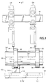
- FIG. 1 is a front view of an exemplary embodiment of the tool positioner shown in relation to circular slitting knives to be positioned.
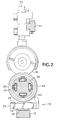
- FIG. 2 is a cross-sectional view taken along line 2-2 of FIG. 1.
- FIG. 3 is an enlarged top view of the tool positioner of FIG. 1.
- FIG. 4 is a cross-sectional view taken along line 4-4 of FIG. 3.
- FIG. 5 is a cross-sectional view taken along line 5-5 of FIG. 3.
- FIG. 6 is an enlarged cross-sectional view taken along line 6-6 of FIG. 3.
- FIG. 7 is a cross-sectional view corresponding to FIG. 4 showing the tool positioner in a tool-contacting condition.
- FIG. 8 is a cross-sectional view corresponding to FIG. 5 showing the tool positioner in a tool-contacting condition.
- FIG. 9 is a top view of the tool positioner corresponding to FIG. 8.
- An exemplary embodiment of a tool positioner includes a conventional linear actuator 12 having a carriage 14 movable along the actuator's tool-positioning axis 16 which is shown in phantom in FIG. 1.
- the linear actuator may include a motor-driven reversible continuous belt such as 18 to which the carriage 14 is connected or, alternatively, a motor-driven screw (not shown) for reversibly controlling the linear movement of the carriage 14 along the axis 16.
- Control of the motor-driven linear actuator 12 is accomplished by any suitable computer-operated control system enabling an operator to pre-set desired target positions parallel to the axis 16 and then move the carriage 14 to those positions.
- a conventional pulse-counting position sensor determines when the linear actuator has moved the carriage 14 to the desired target position, at which time the actuator's motor drive is stopped.
- Control systems of this general type are exemplified by Miller et al. U.S. Patent No. 5,125,301 which is incorporated herein by reference.
- a tool-contacting assembly comprising a base 20 with a tool-contacting fixture 22 movably mounted thereon so as to be selectively extensible upwardly along a path generally transverse to the tool-positioning axis 16 by extension of a pneumatic piston 24 (FIG. 7) against the biasing force of a cantilevered leaf spring 26 which secures the tool-contacting fixture 22 to the base 20 by means of screws 27.
- the path along which extension and retraction of the tool-contacting fixture 22 occurs is a curved path generally transverse to the axis 16, due to the cantilevered mounting of the spring 26.
- the extension/ retraction path could be linear.
- the tool positioner 10 is located closely adjacent to an elongate tool-supporting member such as a shaft 28, extending parallel to the axis 16, upon which a plurality of tools 30 are mounted.
- the shaft 28 may be any of numerous different types of drive shafts capable of selectivity fixing the tools 30 to the shaft at different positions and selectively releasing them so that they can be repositioned.
- a suitable pneumatically-expandable shaft would be one such as that shown in Miller et al. U.S. Patent No. 5,372,331, modified to have straight longitudinal slots 32 and resilient pneumatically expandable bladders 34. With the bladders 34 in an unexpanded condition, the tools 30 are released from the shaft 28 and can slide along the shaft parallel to the axis 16.
- the tools 30 are locked to the shaft in their respective positions.
- Alternatives to the shaft 28 could include rails or other elongate tool-supporting members along which tools can move in sliding or rolling engagement unless locked to the tool-supporting member by similar pneumatically or mechanically expandable devices on the supporting member, or by locking elements on the tools themselves.
- the exemplary tools 30 are circular slitting knives having opposed peripheral cutting edges 36 and 38. Either of the edges 36, 38 can be used to cooperate with corresponding upper circular slitting knives 39 positionable along a rail 41 for cutting web materials into varying widths depending upon the positioning of the knives.
- a typical upper slitting knife structure is shown in greater detail in Tidland et al. U.S. Patent No. 5,083,489, which is incorporated herein by reference. Virtually any other type of powered or non-powered tool for cutting, creasing, scoring, punching, drilling, etc., whether positionable along shafts, rails or other tool-supporting members, could be positioned in accordance with the present invention.
- the tool-contacting fixture 22 of the tool positioner 10 comprises a bottom plate 40 atop which is mounted a rectangularly shaped peripheral frame 42 having a generally rectangular aperture in its center so as to form a depression surrounded by the frame 42.
- the leaf spring 26, frame 42, and bottom plate 40 are rigidly connected together by screws 44.
- An opposed pair of tool-contacting positioning members 48, 50 comprising upwardly converging cylindrical metal rods affixed to the inner surface of the frame 42, terminate at respective tool-contacting single points 48a and 50a so that they can push against a respective side 30a or 30b of a tool 30 at a single point, as shown in FIG. 8 with respect to side 30a and point 48a.
- Single point contact is enabled by the cylindrical shape of the member 48 or 50 and its angular relationship to the side surface 30a or 30b of the tool as shown in FIG. 8. Such single point contact enhances positioning accuracy and, in the case of a tool 30 such as that shown having cutting edges 36, 38, enables contact with the tool at a point removed from the cutting edge so that dulling or other damage to the cutting edge is prevented.
- rollers 52 Resting on the bottom plate 40 of the tool-contacting fixture 22 are a pair of steel rollers 52 each journaled rotatably about a respective flexible wire axle 54, as shown in FIG. 6. Each axle 54 in turn is secured within a respective elastomer tube 56 clamped between the bottom plate 40 and the interior margin of the leaf spring 26 as shown in FIG. 6.
- the rollers 52 are spaced apart parallel to the tool-positioning axis 16 and can roll along the bottom plate 40 parallel to the axis 16 in either direction from their centered positions of FIG. 4. Such a displacement from their centered positions is shown, for example, in FIGS. 8 and 9. When so displaced, the rollers 52 are spring-biased toward their centered positions by the elastomer tubes 56.
- the rollers 52 and their supporting bottom plate 40 constitute a stabilizing tool-contacting member capable of exerting a pushing force against the tool 30 in a direction transverse to the axis 16 and toward the tool supporting member 28 in response to the extension of the piston 24 upon opening of its solenoid-operated air supply valve 58, as further explained below.
- the corresponding upper knives 39 are retracted upwardly by release of air pressure on their upwardly spring-biased pistons 59 in a conventional manner.
- the bladders 34 of the shaft 28 are relieved of their pneumatic pressure and retracted within the slots 32, thereby releasing the tools 30 so that they can slide freely along the shaft 28.
- the tool-contacting fixture 22 is in its retracted condition as shown in FIGS. 4 and 5 due to the closure of the air supply valve 58, which simultaneously exhausts the pressure on the piston 24 and enables the leaf spring 26 to retract the fixture 22.
- the linear actuator 12 first moves the retracted fixture 22 along the axis 16 to locate an edge 36 or 38 of each tool 30 by means of an inductive sensor 60 and store its location in computer memory.
- the memory also contains prestored information regarding the widths of the tools 30 so that their centers along the axis 16 are likewise known from their edge locations.
- the retracted fixture 22 is centered by the control system on the first tool 30 to be positioned along the axis 16 so that both of the tool-contacting positioning members 48, 50 are located outboard of the respective proximate sides 30a, 30b of the tool 30 as shown in FIG. 5.
- the solenoid valve 58 is opened by the control system and the piston 24 extends the tool-contacting fixture 22 upwardly toward the tool 30 as shown in FIG.
- the control system causes the linear actuator 12 to move the fixture 22 in the desired direction along the axis 16, causing the appropriate tool-contacting positioning member 48 or 50 to contact the side 30a or 30b of the tool 30 while simultaneously maintaining the radial pushing force against the tool through the rollers 52.
- Such movement to the left for example, as shown in FIG. 8, causes the member 48 to contact the side 30a at the point 48a.
- the bottom plate 40 of the fixture 22 likewise moves along the axis 16 relative to the tool 30, causing the rollers 52 to roll sideways relative both to the tool 30 and to the bottom plate 40 into off-center positions as shown in FIGS. 8 and 9.
- the off-center displacement of the rollers 52 relative to the tool 30 is small, being only half the translation of the tool-contacting member 48 relative to the tool 30.
- the linear actuator 12 continues to move the fixture 22 to the left along the axis 16 as shown in FIG. 8, causing the tool-contacting member 48 to push the tool 30 slidably along the shaft 28 toward its new position while the radial pushing force of the rollers 52 under the influence of the piston 24 is maintained.
- This radial pushing force resists any tendency of the pushing force exerted by the member 48 to tilt the tool 30 obliquely relative to the tool-positioning axis 16 during the repositioning movement.
- any other tools 30 are obstructing the path of the particular tool being pushed, they will be pushed ahead of the particular tool.
- the actuator 12 stops and reverses its direction thereby causing the opposite tool-contacting positioning member 50 to contact the opposite side 30b of the tool 30 and push it back toward its desired position in the manner previously described with respect to the member 48.
- any resistance of other tools 30, which may have previously been pushed ahead of the particular tool being positioned is eliminated prior to final positioning to maximize accuracy. If the side 30b of the tool has the cutting edge intended to be used, the actuator 12 moves the fixture 22 exactly to the desired position and stops.
- the actuator 12 once again moves the tool slightly beyond the desired position and again reverses direction so that final positioning of the tool will be performed by the member 48 pushing against the side 30a of the tool.
- the actuator 12 halts the fixture 22 and reverses direction until the fixture 22 is once again stopped at a location centered on the tool along the axis 16, so that both members 48 and 50 no longer contact the tool 30.
- the valve 58 is then closed by the control system, exhausting the pressure on the piston 24 and enabling the leaf spring 26 to retract the fixture 22 away from the tool 30.
- Other tools 30 on the shaft 28 are thereafter repositioned, if necessary, in a similar manner in any convenient sequence until all tools 30 are in their proper positions, after which the bladders 34 on the shaft 28 are inflated to lock the tools to the shaft in their desired positions.
- the upper tools 39 are similarly repositioned by their own tool-positioning apparatus before, after, or concurrently with the repositioning of the lower tools 30.
- the upper tools may be repositioned by the tool positioner 10 concurrently with the lower tools by interconnecting corresponding upper and lower tools prior to repositioning.
- the rollers 52 serve as friction-reducing means to enable the bottom plate 40 of the fixture 22 to move along the axis 16 relative to the tool 30 while simultaneously exerting a radial pushing force against the tool 30. Their purpose is to cause the frictional resistance between the plate 40 and the tool 30 along the axis 16 to be less than the sliding resistance between the tool 30 and the shaft 28. Without such a friction-reducing means of some type, such as rollers, ball bearings or the like, the frictional resistance between the plate 40 and the tool 30 would be as great as or greater than the frictional resistance between the tool 30 and the shaft 28.
- the plate 40 could, within the scope of the invention, be separate from the tool-contacting members 48 and 50 so as not to be required to move in unison with them along the axis 16. However this would require separate actuation of the members 48 and 50 which would require a more complex structure.
Landscapes
- Life Sciences & Earth Sciences (AREA)
- Forests & Forestry (AREA)
- Engineering & Computer Science (AREA)
- Mechanical Engineering (AREA)
- Details Of Cutting Devices (AREA)
- Automatic Tool Replacement In Machine Tools (AREA)
- Bending Of Plates, Rods, And Pipes (AREA)
- Perforating, Stamping-Out Or Severing By Means Other Than Cutting (AREA)
- Jigs For Machine Tools (AREA)
Applications Claiming Priority (2)
| Application Number | Priority Date | Filing Date | Title |
|---|---|---|---|
| US08/549,657 US5735184A (en) | 1995-10-27 | 1995-10-27 | Powered tool positioner system |
| US549657 | 1995-10-27 |
Publications (2)
| Publication Number | Publication Date |
|---|---|
| EP0770460A2 true EP0770460A2 (fr) | 1997-05-02 |
| EP0770460A3 EP0770460A3 (fr) | 1997-10-01 |
Family
ID=24193911
Family Applications (1)
| Application Number | Title | Priority Date | Filing Date |
|---|---|---|---|
| EP96307536A Withdrawn EP0770460A3 (fr) | 1995-10-27 | 1996-10-17 | Dispositif de positionnement motorisé pour outils |
Country Status (4)
| Country | Link |
|---|---|
| US (1) | US5735184A (fr) |
| EP (1) | EP0770460A3 (fr) |
| JP (1) | JPH09168934A (fr) |
| CA (1) | CA2187144C (fr) |
Cited By (7)
| Publication number | Priority date | Publication date | Assignee | Title |
|---|---|---|---|---|
| WO2000046001A1 (fr) * | 1999-02-03 | 2000-08-10 | Wilhelm Bilstein Kg Spezialfabrik Für Rundmesser Und Plattenventile | Dispositif pour decouper longitudinalement des bandes de materiau, comportant une unite de positionnement pour les guide-lames |
| FR2798878A1 (fr) * | 1999-09-24 | 2001-03-30 | Eastman Kodak Co | Dispositif et procede pour positionner un couteau par rapport a son contre-couteau |
| WO2001085408A2 (fr) * | 2000-05-12 | 2001-11-15 | Wilhelm Bilstein KG Spezialfabrik für Maschinenmesser und Kompressorventile | Procede de positionnement de lames inferieures sur un dispositif pour separer une bande de materiau en longueur |
| EP1245354A1 (fr) * | 2001-03-26 | 2002-10-02 | A. CELLI S.p.A | Dispositif pour le positionnement d'outils de coupe, système de coupe comprenant un tel dispositif ainsi que rebobineuse ayant un tel système de coupe |
| WO2008103117A1 (fr) * | 2007-02-22 | 2008-08-28 | Trancel Restatic Aktiebolag | Ensemble de couteaux |
| WO2009055199A2 (fr) | 2007-10-24 | 2009-04-30 | Services Petroliers Schlumberger | Trépan transformable |
| CN108025379A (zh) * | 2016-04-19 | 2018-05-11 | Jdc株式会社 | 轴体插入物的配置装置 |
Families Citing this family (15)
| Publication number | Priority date | Publication date | Assignee | Title |
|---|---|---|---|---|
| US6012372A (en) * | 1996-01-18 | 2000-01-11 | Laster; James E. | Adjustable arbor and cutting elements |
| ES2183352T3 (es) | 1997-03-18 | 2003-03-16 | Raimann Holzoptimierung Gmbh & | Dispositivo de corte a medida con una anchura opcional para madera u otros materiales. |
| DE19832871C1 (de) * | 1998-07-22 | 2000-05-31 | Voith Sulzer Papiertech Patent | Verfahren und Vorrichtung zum Längsschneiden einer Materialbahn |
| JP2943110B1 (ja) * | 1998-08-24 | 1999-08-30 | 株式会社ミヤコシ | ランダム縦ミシン目加工装置 |
| US6059218A (en) * | 1999-01-28 | 2000-05-09 | Nim-Cor, Inc. | Airlock shaft with differential core speed slipping capability |
| US6732625B1 (en) | 2000-04-28 | 2004-05-11 | Tidland Corporation | Easily adjusted web slitter |
| DE10034719A1 (de) * | 2000-07-17 | 2002-01-31 | Josef Froehling Gmbh Walzwerks | Längsteilschere |
| US20060162520A1 (en) * | 2004-05-28 | 2006-07-27 | Raimann Holzoptimierung Gmbh & Co. Kg, De | Device for cutting any width of wood or other materials |
| US8047110B2 (en) * | 2004-12-29 | 2011-11-01 | Catbridge Machinery, L.L.C. | Positioning system and carriage assembly for converting machines |
| ES2315855T3 (es) * | 2005-02-28 | 2009-04-01 | A. Celli Nonwovens S.P.A. | Dispositivo para el corte longitudinal de una banda de material continua y una maquina que comprende dicho dispositivo. |
| US20090151534A1 (en) * | 2007-11-09 | 2009-06-18 | Rooke C Aldon | Slitter Line Knife Holder Assembly |
| US20090151533A1 (en) * | 2007-11-09 | 2009-06-18 | Wenzhao Lan | Slitting Machine |
| US8479623B2 (en) * | 2009-02-02 | 2013-07-09 | Patrick Cudahy, Inc. | Cooked bacon slicer |
| CN105058503A (zh) * | 2015-08-05 | 2015-11-18 | 领胜电子科技(成都)有限公司 | 一种风扇式模切机 |
| CN115709500B (zh) * | 2023-01-09 | 2023-05-05 | 享成安全科技(南京)有限公司 | 一种消防管道带压打孔装置 |
Citations (4)
| Publication number | Priority date | Publication date | Assignee | Title |
|---|---|---|---|---|
| US4033217A (en) | 1976-01-13 | 1977-07-05 | S&S Corrugated Paper Machinery Co., Inc. | Slitter having carrier for selective adjustment of a plurality of heads |
| US5083489A (en) | 1989-01-03 | 1992-01-28 | Tidland Corporation | Control system for web slitting machine |
| US5125301A (en) | 1988-06-03 | 1992-06-30 | Tidland Corporation | System for automatically positioning multiple tool-holding carriages |
| US5372331A (en) | 1993-06-15 | 1994-12-13 | Tidland Corporation | Expansible shaft for roll core |
Family Cites Families (17)
| Publication number | Priority date | Publication date | Assignee | Title |
|---|---|---|---|---|
| US523298A (en) * | 1894-07-17 | upton | ||
| US3587374A (en) * | 1969-04-11 | 1971-06-28 | Koppers Co Inc | Presettable slitter-scorer apparatus |
| US3646418A (en) * | 1969-07-22 | 1972-02-29 | Logic Systems Inc | Positioning of multiple elements |
| DE2047503B2 (de) * | 1970-09-26 | 1973-10-04 | Werner H. K. Peters Maschinenfabrik Gmbh, 2000 Hamburg | Vorrichtung zum Rillen und/oder Langs schneiden einer durchlaufenden Bahn aus Pap pe, Papier od dgl |
| US4010677A (en) * | 1974-06-14 | 1977-03-08 | Mitsubishi Jukogyo Kabushiki Kaisha | Apparatus for positioning heads |
| DE2832982A1 (de) * | 1977-08-11 | 1979-02-22 | Masson Scott Thrissell Eng Ltd | Positionierungsvorrichtung |
| US4237761A (en) * | 1978-05-23 | 1980-12-09 | Molins Machine Company, Inc. | Head locking means for slitter scorer |
| US4230009A (en) * | 1979-02-09 | 1980-10-28 | Molins Machine Company, Inc. | Rotary tool positioner |
| SE416278B (sv) * | 1979-03-22 | 1980-12-15 | Foerenade Fabriksverken | Metod och anordning for instellning av valsringar pa en axel |
| JPH0659636B2 (ja) * | 1986-01-27 | 1994-08-10 | 三菱重工業株式会社 | ヘツドの位置決め装置 |
| US4926730A (en) * | 1988-08-30 | 1990-05-22 | Garrett Jimmy R | Guide for slotting, scoring, trimming or like heads |
| DE3938278C2 (de) * | 1989-11-17 | 1993-12-09 | Jagenberg Ag | Vorrichtung zum Positionieren von entlang Führungen bewegbaren Schlitten oder dergleichen |
| DE4005271C1 (fr) * | 1990-02-20 | 1991-10-02 | Reinhardt Maschinenbau Gmbh, 7032 Sindelfingen, De | |
| DE4106069C1 (fr) * | 1991-02-27 | 1992-05-21 | J.M. Voith Gmbh, 7920 Heidenheim, De | |
| US5325751A (en) * | 1993-02-17 | 1994-07-05 | Mereen-Johnson Machine Company | Gang rip saw assembly |
| DE4337902C2 (de) * | 1993-11-08 | 1997-01-16 | Kammann Spezialmaschinen Und S | Stanze für Bahnmaterial |
| DE9410069U1 (de) * | 1994-06-22 | 1994-09-15 | Dienes Werke für Maschinenteile GmbH & Co KG, 51491 Overath | Positioniereinrichtung für Untermesser bei Längsschneidemaschinen |
-
1995
- 1995-10-27 US US08/549,657 patent/US5735184A/en not_active Expired - Fee Related
-
1996
- 1996-10-04 CA CA002187144A patent/CA2187144C/fr not_active Expired - Fee Related
- 1996-10-17 EP EP96307536A patent/EP0770460A3/fr not_active Withdrawn
- 1996-10-25 JP JP8283746A patent/JPH09168934A/ja active Pending
Patent Citations (4)
| Publication number | Priority date | Publication date | Assignee | Title |
|---|---|---|---|---|
| US4033217A (en) | 1976-01-13 | 1977-07-05 | S&S Corrugated Paper Machinery Co., Inc. | Slitter having carrier for selective adjustment of a plurality of heads |
| US5125301A (en) | 1988-06-03 | 1992-06-30 | Tidland Corporation | System for automatically positioning multiple tool-holding carriages |
| US5083489A (en) | 1989-01-03 | 1992-01-28 | Tidland Corporation | Control system for web slitting machine |
| US5372331A (en) | 1993-06-15 | 1994-12-13 | Tidland Corporation | Expansible shaft for roll core |
Cited By (11)
| Publication number | Priority date | Publication date | Assignee | Title |
|---|---|---|---|---|
| WO2000046001A1 (fr) * | 1999-02-03 | 2000-08-10 | Wilhelm Bilstein Kg Spezialfabrik Für Rundmesser Und Plattenventile | Dispositif pour decouper longitudinalement des bandes de materiau, comportant une unite de positionnement pour les guide-lames |
| FR2798878A1 (fr) * | 1999-09-24 | 2001-03-30 | Eastman Kodak Co | Dispositif et procede pour positionner un couteau par rapport a son contre-couteau |
| WO2001085408A2 (fr) * | 2000-05-12 | 2001-11-15 | Wilhelm Bilstein KG Spezialfabrik für Maschinenmesser und Kompressorventile | Procede de positionnement de lames inferieures sur un dispositif pour separer une bande de materiau en longueur |
| WO2001085408A3 (fr) * | 2000-05-12 | 2002-06-20 | Bilstein Spezialfab Wilhelm | Procede de positionnement de lames inferieures sur un dispositif pour separer une bande de materiau en longueur |
| DE10023210B4 (de) * | 2000-05-12 | 2004-03-11 | Wilhelm Bilstein KG Spezialfabrik für Maschinenmesser und Kompressorventile | Verfahren zur Positionierung von Untermessern an einer Einrichtung zum Längsteilen einer Materialbahn |
| EP1245354A1 (fr) * | 2001-03-26 | 2002-10-02 | A. CELLI S.p.A | Dispositif pour le positionnement d'outils de coupe, système de coupe comprenant un tel dispositif ainsi que rebobineuse ayant un tel système de coupe |
| WO2008103117A1 (fr) * | 2007-02-22 | 2008-08-28 | Trancel Restatic Aktiebolag | Ensemble de couteaux |
| WO2009055199A2 (fr) | 2007-10-24 | 2009-04-30 | Services Petroliers Schlumberger | Trépan transformable |
| CN108025379A (zh) * | 2016-04-19 | 2018-05-11 | Jdc株式会社 | 轴体插入物的配置装置 |
| EP3254791A4 (fr) * | 2016-04-19 | 2018-08-08 | JDC, Inc. | Appareil de placement pour inserts de corps d'arbre |
| CN108025379B (zh) * | 2016-04-19 | 2019-07-30 | Jdc株式会社 | 轴体插入物的配置装置 |
Also Published As
| Publication number | Publication date |
|---|---|
| US5735184A (en) | 1998-04-07 |
| CA2187144C (fr) | 2000-04-18 |
| EP0770460A3 (fr) | 1997-10-01 |
| CA2187144A1 (fr) | 1997-04-28 |
| JPH09168934A (ja) | 1997-06-30 |
Similar Documents
| Publication | Publication Date | Title |
|---|---|---|
| US5735184A (en) | Powered tool positioner system | |
| US6245004B1 (en) | Machine for performing a manufacturing operation on a sheet of material and method of operation | |
| US4546681A (en) | Multi-purpose steady rest | |
| US4462292A (en) | Apparatus for cutting and notching sheet material | |
| JP4724319B2 (ja) | 段ボールのウエブのための縦加工処理機械 | |
| US4047457A (en) | Sheet metal cutting | |
| EP0603152B1 (fr) | Dispositif pour la découpe d'un panneau de verre | |
| JPH09141352A (ja) | 倍力装置 | |
| JPH0755471B2 (ja) | カッター組立体 | |
| US5383380A (en) | Material cutting machine for slicing a cylinder | |
| JPH0117770B2 (fr) | ||
| CA2058806A1 (fr) | Machine a souder des bandes metalliques | |
| JPH06206132A (ja) | 内蔵中心線調節機構を有する固定振れ止め | |
| JP2004520945A5 (fr) | ||
| EP1676681A1 (fr) | système de positionnement et chariot pour une machine a refendre et de transformation | |
| US5025693A (en) | Side shifting apparatus for cutting blade in a web slitting machine | |
| US4004333A (en) | Punching, contouring, handling apparatuses and method | |
| JPH08257824A (ja) | 中空パイプの切断及び切欠き加工を行なう方法及び装置 | |
| US5083489A (en) | Control system for web slitting machine | |
| AU3437302A (en) | System for mounting and removing the blankets of a rotary cutting anvil cylinder | |
| DE2205883B2 (de) | Vorrichtung zum Aufschneiden von Rohren | |
| US5970774A (en) | Apparatus and method for corner cutting and edge bending of lithographic plates | |
| US20100071524A1 (en) | Apparatus for cutting sheet material | |
| US20120291604A1 (en) | Apparatus for cutting sheet material | |
| US5133206A (en) | Method and apparatus for reforming a portion of a member to a predetermined reference position |
Legal Events
| Date | Code | Title | Description |
|---|---|---|---|
| PUAI | Public reference made under article 153(3) epc to a published international application that has entered the european phase |
Free format text: ORIGINAL CODE: 0009012 |
|
| AK | Designated contracting states |
Kind code of ref document: A2 Designated state(s): DE FR GB IT |
|
| PUAL | Search report despatched |
Free format text: ORIGINAL CODE: 0009013 |
|
| AK | Designated contracting states |
Kind code of ref document: A3 Designated state(s): DE FR GB IT |
|
| 17P | Request for examination filed |
Effective date: 19971115 |
|
| 17Q | First examination report despatched |
Effective date: 19981102 |
|
| GRAG | Despatch of communication of intention to grant |
Free format text: ORIGINAL CODE: EPIDOS AGRA |
|
| STAA | Information on the status of an ep patent application or granted ep patent |
Free format text: STATUS: THE APPLICATION HAS BEEN WITHDRAWN |
|
| 18W | Application withdrawn |
Withdrawal date: 20011117 |