EP0770416B1 - Filtre d'agent refroidisseur - Google Patents
Filtre d'agent refroidisseur Download PDFInfo
- Publication number
- EP0770416B1 EP0770416B1 EP96114928A EP96114928A EP0770416B1 EP 0770416 B1 EP0770416 B1 EP 0770416B1 EP 96114928 A EP96114928 A EP 96114928A EP 96114928 A EP96114928 A EP 96114928A EP 0770416 B1 EP0770416 B1 EP 0770416B1
- Authority
- EP
- European Patent Office
- Prior art keywords
- casing
- chamber
- coolant
- fact
- joined
- Prior art date
- Legal status (The legal status is an assumption and is not a legal conclusion. Google has not performed a legal analysis and makes no representation as to the accuracy of the status listed.)
- Expired - Lifetime
Links
- 239000002826 coolant Substances 0.000 title claims description 52
- 239000012528 membrane Substances 0.000 claims description 17
- 239000000654 additive Substances 0.000 claims description 15
- 230000000996 additive effect Effects 0.000 claims description 10
- 239000002184 metal Substances 0.000 claims description 2
- 210000004379 membrane Anatomy 0.000 description 11
- 239000007788 liquid Substances 0.000 description 5
- 239000007787 solid Substances 0.000 description 4
- 238000000034 method Methods 0.000 description 3
- 238000001816 cooling Methods 0.000 description 2
- 230000000694 effects Effects 0.000 description 2
- 238000004519 manufacturing process Methods 0.000 description 2
- 238000002156 mixing Methods 0.000 description 2
- 238000002485 combustion reaction Methods 0.000 description 1
- 230000000295 complement effect Effects 0.000 description 1
- 239000000498 cooling water Substances 0.000 description 1
- 238000001914 filtration Methods 0.000 description 1
- 230000009969 flowable effect Effects 0.000 description 1
- 239000011888 foil Substances 0.000 description 1
- 239000000463 material Substances 0.000 description 1
- 238000007789 sealing Methods 0.000 description 1
- 230000000087 stabilizing effect Effects 0.000 description 1
- 230000001960 triggered effect Effects 0.000 description 1
Images


Classifications
-
- F—MECHANICAL ENGINEERING; LIGHTING; HEATING; WEAPONS; BLASTING
- F01—MACHINES OR ENGINES IN GENERAL; ENGINE PLANTS IN GENERAL; STEAM ENGINES
- F01P—COOLING OF MACHINES OR ENGINES IN GENERAL; COOLING OF INTERNAL-COMBUSTION ENGINES
- F01P11/00—Component parts, details, or accessories not provided for in, or of interest apart from, groups F01P1/00 - F01P9/00
- F01P11/06—Cleaning; Combating corrosion
-
- B—PERFORMING OPERATIONS; TRANSPORTING
- B01—PHYSICAL OR CHEMICAL PROCESSES OR APPARATUS IN GENERAL
- B01D—SEPARATION
- B01D27/00—Cartridge filters of the throw-away type
- B01D27/04—Cartridge filters of the throw-away type with cartridges made of a piece of unitary material, e.g. filter paper
- B01D27/06—Cartridge filters of the throw-away type with cartridges made of a piece of unitary material, e.g. filter paper with corrugated, folded or wound material
-
- B—PERFORMING OPERATIONS; TRANSPORTING
- B01—PHYSICAL OR CHEMICAL PROCESSES OR APPARATUS IN GENERAL
- B01D—SEPARATION
- B01D27/00—Cartridge filters of the throw-away type
- B01D27/08—Construction of the casing
-
- B—PERFORMING OPERATIONS; TRANSPORTING
- B01—PHYSICAL OR CHEMICAL PROCESSES OR APPARATUS IN GENERAL
- B01D—SEPARATION
- B01D29/00—Filters with filtering elements stationary during filtration, e.g. pressure or suction filters, not covered by groups B01D24/00 - B01D27/00; Filtering elements therefor
- B01D29/11—Filters with filtering elements stationary during filtration, e.g. pressure or suction filters, not covered by groups B01D24/00 - B01D27/00; Filtering elements therefor with bag, cage, hose, tube, sleeve or like filtering elements
- B01D29/13—Supported filter elements
- B01D29/15—Supported filter elements arranged for inward flow filtration
- B01D29/21—Supported filter elements arranged for inward flow filtration with corrugated, folded or wound sheets
-
- B—PERFORMING OPERATIONS; TRANSPORTING
- B01—PHYSICAL OR CHEMICAL PROCESSES OR APPARATUS IN GENERAL
- B01D—SEPARATION
- B01D29/00—Filters with filtering elements stationary during filtration, e.g. pressure or suction filters, not covered by groups B01D24/00 - B01D27/00; Filtering elements therefor
- B01D29/96—Filters with filtering elements stationary during filtration, e.g. pressure or suction filters, not covered by groups B01D24/00 - B01D27/00; Filtering elements therefor in which the filtering elements are moved between filtering operations; Particular measures for removing or replacing the filtering elements; Transport systems for filters
-
- B—PERFORMING OPERATIONS; TRANSPORTING
- B01—PHYSICAL OR CHEMICAL PROCESSES OR APPARATUS IN GENERAL
- B01D—SEPARATION
- B01D37/00—Processes of filtration
- B01D37/02—Precoating the filter medium; Addition of filter aids to the liquid being filtered
- B01D37/025—Precoating the filter medium; Addition of filter aids to the liquid being filtered additives incorporated in the filter
-
- B—PERFORMING OPERATIONS; TRANSPORTING
- B01—PHYSICAL OR CHEMICAL PROCESSES OR APPARATUS IN GENERAL
- B01D—SEPARATION
- B01D2201/00—Details relating to filtering apparatus
- B01D2201/04—Supports for the filtering elements
- B01D2201/0415—Details of supporting structures
-
- B—PERFORMING OPERATIONS; TRANSPORTING
- B01—PHYSICAL OR CHEMICAL PROCESSES OR APPARATUS IN GENERAL
- B01D—SEPARATION
- B01D2201/00—Details relating to filtering apparatus
- B01D2201/30—Filter housing constructions
- B01D2201/301—Details of removable closures, lids, caps, filter heads
- B01D2201/305—Snap, latch or clip connecting means
-
- B—PERFORMING OPERATIONS; TRANSPORTING
- B01—PHYSICAL OR CHEMICAL PROCESSES OR APPARATUS IN GENERAL
- B01D—SEPARATION
- B01D2201/00—Details relating to filtering apparatus
- B01D2201/40—Special measures for connecting different parts of the filter
- B01D2201/4084—Snap or Seeger ring connecting means
-
- F—MECHANICAL ENGINEERING; LIGHTING; HEATING; WEAPONS; BLASTING
- F01—MACHINES OR ENGINES IN GENERAL; ENGINE PLANTS IN GENERAL; STEAM ENGINES
- F01P—COOLING OF MACHINES OR ENGINES IN GENERAL; COOLING OF INTERNAL-COMBUSTION ENGINES
- F01P11/00—Component parts, details, or accessories not provided for in, or of interest apart from, groups F01P1/00 - F01P9/00
- F01P11/06—Cleaning; Combating corrosion
- F01P2011/065—Flushing
Definitions
- the present invention relates to coolant filters according to the preamble of claims 1 to 3.
- Such coolant filters are out of practical operation known. They are used for filtering the coolant on an internal combustion engine and to complement the Coolant additive used. You can stand as and also be designed as a hanging housing. In these A new filter insert is used in the housing during service.
- the stabilizing filter end plates are useful made of a combustible material and on the outer circumference is a pleated filter medium, For example, made of paper attached to a also supports combustible inner dome.
- a coolant additive in solid form which liquefies when cooling water flows through it and so after an undefined period of time the desired one Mixing ratio of the additive in the cooling circuit manufactures.
- coolant filters can only absorb coolant additives in solid form.
- a filter with a housing known that can be sealingly connected to a motor housing is, with a hollow cylindrical filter insert that is radial can be flowed through from the outside in, with and outlet openings, the filter in the interior of the filter insert one with an outer skin on all sides has a closed chamber for additives.
- the chamber is closed at the front with membranes, which exposed to heat after connecting the housing with the motor housing after a long time has passed Open time.
- the filter described here deals it is an oil filter, the additives first after a longer runtime of the associated engine, for example about 10,000 km, in the oil of the oil circuit should be mixed in to restore the quality of the oil to improve and so an oil change is only necessary later close.
- the length of the mandrel is to be dimensioned such that the way that the two housing parts travel to each other to be connected is slightly larger than that Length of the mandrel.
- the cam is on the Chamber fastens and presses into it when the two housing parts are connected to each other.
- the chamber advantageously has a generally cylindrical shape a coat and two faces, the coat of the cylinder designed as a support dome of the filter insert and at least one end face is spatially one defined area to open. So that will the space inside the filter insert can be used optimally. At the same time, there is no separate support dome for the filter insert.
- the chamber generally Cylindrical shape and is inside the filter insert can be used, at least one of their two A spatially defined area to be opened on the end faces having.
- the chamber is in slidable in the axial direction.
- the two housing parts by screwed threaded sections are connectable, the one housing part is cup-shaped and the other housing part is the inlet opening and the outlet opening has that on Bottom of the cup-shaped housing part arranged locking means are, with appropriate locking means on one Face plate of the filter insert are connectable that the end of the chamber facing the locking means Has predetermined breaking line, close to the one projecting outwards Cam is arranged, when screwing into each other the housing parts opens the predetermined breaking line, and that the end of the chamber facing away from the locking means Has membrane or predetermined breaking line and when screwing into each other the housing parts with a mandrel can be brought, which is arranged on the other housing part and opens the membrane or predetermined breaking line.
- the filter insert Service of the coolant filter is the filter insert with its locking means on the bottom of the cup-shaped housing part snapped into place. Then the cup-shaped housing part screwed onto the other housing part.
- the Screw-in path which in one version e.g. Is 30 mm, the two housing parts are brought together in such a way and screwed tight that both the mandrel and also the cam when engaging with the membrane or the an end wall of the filter insert open the chamber.
- the chamber is open on both ends and can flow through the coolant, which is a direct mixing of the liquid coolant additive from the inside the chamber with the remaining coolant in the cooling circuit has the consequence.
- the housing is cup-shaped and on one of the end walls has a central opening with an internal thread on a corresponding one, comprising the outlet opening Threaded connector of the motor housing can be screwed on that there is at least one inlet opening in the end wall is that on the end wall in the area radially outside an annular seal of the at least one inlet opening is attached after screwing the housing sealing against the motor housing that the threaded connector facing end of the chamber a predetermined breaking line has, near which an outwardly projecting Cam is arranged when screwing the housing the breaking line opens, and that the other end the chamber has a membrane or predetermined breaking line and when screwing on the housing with a mandrel can be brought into engagement, which is arranged on the threaded connector and opens the membrane or predetermined breaking line.
- the advantageous effect of this configuration is same as the one described above, only that in this embodiment, a screw-on cup-shaped Housing that is used as a spin-on filter as such is known.
- the chamber expediently points to at least one of them On the end faces spacing-forming projections, their height is less than that of the cam. This is a good one Flow path created with sufficient flow cross-section.
- the chamber is expediently made of plastic, which creates a easy manufacture is guaranteed.
- the membrane is advantageously a plastic or metal foil, which also makes it easy to manufacture is guaranteed.
- the membrane is preferred through a thinned area the outer skin.
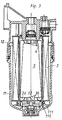
- the coolant filter a housing 1, which includes an upper housing part 11, which is cup-shaped and one at the open edge Threaded section carries with a seal, and a lower one Housing part 12, in which an inlet opening 13 and an outlet opening 14 for the coolant are.
- a shut-off valve 5 is attached in front of the inlet opening 13 and the outlet opening 14.
- the structure of the housing 1 is from known designs as such presuppose as known and must take part in this Not explained in more detail.
- a filter insert 2 which two Face washers and a folded edge for example Paper.
- the filter insert 2 is radial from flowed through outside inside.
- FIG. 2 shows the two housing parts 11 and 12 in screwed together, with a chamber 3 in Inside the filter insert 2 is already open.
- the filter insert 2 has on its lower face plate Locking means 111 on, with locking means 110 on the housing part 11 can be brought into engagement. This latching is known as such.
- the chamber 3 is in the embodiment shown with a Jacket executed as the support dome 35 for the filter insert 2 serves.
- the chamber faces the lower end in FIG 3 a cam 32, next to which a predetermined breaking line 34 is executed in the end wall.
- a predetermined breaking line 34 is executed in the end wall.
- the predetermined breaking line is already triggered by the Cam 32 when screwing the two housing parts together 11 and 12 broken open.
- Chamber 3 It is also on its top end face in FIG. 2 Chamber 3 has been opened in this process, a Mandrel 4 on the upper housing part 12 in the axial direction protruding is attached, a membrane 31 on the upper Front of the chamber 3 has broken open.
- the chamber 3 can thus be flowed through in the axial direction.
- FIG. 3 shows another embodiment of a chamber 3.
- the chamber 3 is on all sides closed, inside the filter insert 2 usable chamber trained, the jacket not as Support cathedral serves.
- 11 and 12 press the cam 32 against the lower end plate filter insert 2 and opens one next to it horizontal, not marked breaking line, whereby the lower end wall of chamber 3 is open.
- the mandrel 4 is arranged similar to the configuration in FIG. 2, through another predetermined breaking line or a thin wall area at the lower end of chamber 3 and opens this.
- the attachment with locking means 110 and 111 corresponds the execution in FIG. 2.
- FIG. 4 shows a further embodiment of the coolant filter.
- a cup-shaped housing 1 contains one Filter insert 2. Inside the filter insert 2 is introduced a chamber 3, which is generally cylindrical is trained. On the lower end face in FIG. 4 the chamber 3 is a cam 32 near a predetermined breaking line 34 attached, and several projections 36, the height is smaller than the height of the cam 32.
- a predetermined breaking line 31 is attached.
- the housing 1 has an end wall 15 which one Motor housing is not designated, which in Figure 4 above.
- the end wall 15 has a central opening 16 with an internal thread on that on a threaded connector 6 in the motor housing can be screwed on with the appropriate external thread is.
- the outlet opening runs centrally in the threaded connector 6 14 for the filtered medium.
- the end wall 15 also has a plurality of inlet openings 13 through which the medium to be filtered, here the coolant enters the housing 1.
- the threaded connector 6 carries one at its free end Thorn 4.
- the housing 1 is sealed by the ring seal 17 connected to the motor housing.
Claims (11)
- Filtre d'agent refroidisseur qui inclut un carter (1), qui peut être connecté de façon étanche à un carter du moteur ou comporte deux éléments (11, 12) de carter qui peuvent être connectés entre eux de façon détachable et étanche, un insert (2) de filtre à configuration générale cylindrique creuse qui peut être parcouru radialement de l'extérieur vers l'intérieur par l'agent refroidisseur à filtrer, dans lequel le carter (1) comporte une ouverture d'entrée (13) et une ouverture de sortie (14) pour l'agent refroidisseur, et dans lequel une chambre (3) fermée de tous côtés par une enveloppe est agencée dans l'espace intérieur de l'insert (2) de filtre en forme de cylindre creux, contient un complément d'agent refroidisseur et est ouverte lorsque le carter (1) a été connecté avec le carter du moteur ou avec les deux éléments (11, 12) de carter,
caractérisé en ce queau moins une zone de l'enveloppe de la chambre (3) s'ouvre par l'effet d'au moins un moyen mécanique d'ouverture lors de la connexion du carter (1) au carter de moteur ou aux deux éléments (11, 12) de carter, en ce quele moyen d'ouverture est au moins un poinçon (4) monté sur le carter de moteur ou sur un élément (11, 12) de carter, et en ce quela zone à ouvrir consiste en une membrane (31) qui peut être percée par le poinçon (4) unique au moins. - Filtre d'agent refroidisseur qui inclut un carter (1), qui peut être connecté de façon étanche à un carter du moteur ou comporte deux éléments (11, 12) de carter qui peuvent être connectés entre eux de façon détachable et étanche, un insert (2) de filtre à configuration générale cylindrique creuse qui peut être parcouru radialement de l'extérieur vers l'intérieur par l'agent refroidisseur à filtrer, dans lequel le carter (1) comporte une ouverture d'entrée (13) et une ouverture de sortie (14) pour l'agent refroidisseur, et dans lequel une chambre (3) fermée de tous côtés par une enveloppe est agencée dans l'espace intérieur de l'insert (2) de filtre en forme de cylindre creux, contient un complément d'agent refroidisseur et est ouverte lorsque le carter (1) a été connecté avec le carter du moteur ou avec les deux éléments (11, 12) de carter,
caractérisé en ce queau moins une zone de l'enveloppe de la chambre (3) s'ouvre par l'effet d'au moins un moyen mécanique d'ouverture lors de la connexion du carter (1) au carter de moteur ou aux deux éléments (11, 12) de carter, en ce quele moyen d'ouverture est au moins un taquet (32) en saillie vers l'extérieur sur une paroi de face frontale de la chambre (3) et en ce que,une ligne (34) destinée à la rupture qui se rompt lors du contact du taquet unique au moins (32) avec l'élément voisin (11) de carter est agencée près du taquet (32). - Filtre d'agent refroidisseur qui inclut un carter (1), qui peut être connecté de façon étanche à un carter du moteur ou comporte deux éléments (11, 12) de carter qui peuvent être connectés entre eux de façon détachable et étanche, un insert (2) de filtre à configuration générale cylindrique creuse qui peut être parcouru radialement de l'extérieur vers l'intérieur par l'agent refroidisseur à filtrer, dans lequel le carter (1) comporte une ouverture d'entrée (13) et une ouverture de sortie (14) pour l'agent refroidisseur, et dans lequel une chambre (3) fermée de tous côtés par une enveloppe est agencée dans l'espace intérieur de l'insert (2) de filtre en forme de cylindre creux, contient un complément d'agent refroidisseur et est ouverte lorsque le carter (1) a été connecté avec le carter du moteur ou avec les deux éléments (11, 12) de carter,
caractérisé en ce queau moins une zone de l'enveloppe de la chambre (3) s'ouvre par l'effet d'au moins un moyen mécanique d'ouverture lors de la connexion du carter (1) au carter de moteur ou aux deux éléments (11, 12) de carter, en ce quele moyen d'ouverture est au moins un poinçon (4) monté sur le carter de moteur ou sur un élément (11, 12) de carter et/ou au moins au moins un taquet (32) en saillie vers l'extérieur sur une paroi de face frontale de la chambre (3), et en ce queune épaisseur de paroi de la chambre (3) est réduite près du poinçon (4) ou du taquet (32). - Filtre d'agent refroidisseur selon l'une quelconque des revendications 1 à 3, caractérisé en ce que la chambre (3) est d'une forme généralement cylindrique comprenant une virole et deux faces frontales, où la virole du cylindre constitue un dôme de protection (35) de l'insert (2) de filtre et au moins une face frontale comporte une zone à ouvrir de façon définie dans l'espace.
- Filtre d'agent refroidisseur selon l'une quelconque des revendications 1 à 3, caractérisé en ce que la chambre (3) est de configuration généralement cylindrique et peut être insérée dans l'intérieur de l'insert (2) de filtre, au moins l'une des deux faces frontales comportant une zone à ouvrir de façon définie dans l'espace.
- Filtre d'agent refroidisseur selon l'une quelconque des revendications précédentes, caractérisé en ce que les deux éléments (11, 12) de carter peuvent être connectés au moyen de parties filetées vissables l'une dans l'autre, l'un des éléments (11) de carter est en forme de godet et l'autre élément (12) de carter comporte l'ouverture d'entrée (13) et l'ouverture de sortie (14), en ce que le fond de l'élément (11) de carter en forme de godet comporte des moyens d'encliquetage (110) qui peuvent être connectés avec des moyens d'encliquetage correspondants (111) agencés sur un disque frontal de l'insert (2) de filtre, en ce que la face frontale de la chambre (3) tournée vers les moyens d'encliquetage (110, 111) comporte une ligne (34) destinée à la rupture près de laquelle est agencé un taquet (32) en saillie vers l'extérieur qui ouvre la ligne (34) destinée à la rupture lorsque les éléments (11, 12) de carter sont vissés l'un dans l'autre, et en ce que la face frontale de la chambre (3) opposée aux moyens d'encliquetage (110, 111) comporte une membrane ou une ligne (31) destinée à la rupture et peut être amenée, lors du vissage des éléments (11, 12) de carter l'un dans l'autre, au contact d'un poinçon (4) qui est agencé sur l'autre élément (12) de carter et ouvre la membrane ou la ligne (31) destinée à la rupture.
- Filtre pour agent refroidisseur selon l'une quelconque des revendications 1 à 5, caractérisé en ce que le carter (1) est en forme de godet et comporte, sur l'une des parois frontales (15) une ouverture centrale (16) à filet intérieur qui peut être vissé sur un piquage fileté correspondant (6) du carter de moteur qui entoure l'ouverture de sortie (14), en ce qu'au moins une ouverture d'entrée (13) est ménagée dans la paroi frontale (15), en ce qu'un joint d'étanchéité annulaire (17) est monté sur la paroi frontale (15) dans la zone située radialement à l'extérieur de l'ouverture d'entrée (13) unique au moins et repose de façon étanche sur le carter du moteur après vissage du carter (1), en ce que la face frontale de la chambre (3) opposée au piquage fileté (6) comporte une ligne (34) destinée à la rupture près de laquelle est agencé un taquet (32) en saillie vers l'extérieur qui ouvre lors du vissage du carter (1) la ligne (34) destinée à la rupture, et en ce que l'autre face frontale de la chambre (3) comporte une membrane ou une ligne (31) destinée à la rupture et peut être amenée, lors du vissage du carter (1), au contact d'un poinçon (4) qui est agencé sur le piquage fileté (6) et qui ouvre la membrane ou la ligne (31) destinée à la rupture.
- Filtre pour agent refroidisseur selon l'une quelconque des revendications 2 à 7, caractérisé en ce que la chambre (3) comporte, au moins sur l'une de ses faces frontales, des saillies (36) qui forment entretoise et dont la hauteur est inférieure à celle du taquet (32).
- Filtre pour agent refroidisseur selon l'une quelconque des revendications précédentes, caractérisé en ce que la chambre (3) est en matière plastique.
- Filtre pour agent refroidisseur selon l'une quelconque des revendications 1 et 6 à 9, caractérisé en ce que la membrane (31) est une feuille de matière plastique ou de métal.
- Filtre pour agent refroidisseur selon l'une quelconque des revendications 1 et 6 à 10, caractérisé en ce que la membrane consiste en une zone amincie de l'enveloppe.
Applications Claiming Priority (2)
| Application Number | Priority Date | Filing Date | Title |
|---|---|---|---|
| DE19540251A DE19540251C2 (de) | 1995-10-28 | 1995-10-28 | Kühlmittelfilter |
| DE19540251 | 1995-10-28 |
Publications (2)
| Publication Number | Publication Date |
|---|---|
| EP0770416A1 EP0770416A1 (fr) | 1997-05-02 |
| EP0770416B1 true EP0770416B1 (fr) | 2001-11-21 |
Family
ID=7776072
Family Applications (1)
| Application Number | Title | Priority Date | Filing Date |
|---|---|---|---|
| EP96114928A Expired - Lifetime EP0770416B1 (fr) | 1995-10-28 | 1996-09-18 | Filtre d'agent refroidisseur |
Country Status (5)
| Country | Link |
|---|---|
| US (1) | US5753116A (fr) |
| EP (1) | EP0770416B1 (fr) |
| JP (1) | JP4002631B2 (fr) |
| BR (1) | BR9605334A (fr) |
| DE (1) | DE19540251C2 (fr) |
Families Citing this family (51)
| Publication number | Priority date | Publication date | Assignee | Title |
|---|---|---|---|---|
| US5662799A (en) | 1996-06-21 | 1997-09-02 | Fleetguard, Inc. | Slow release coolant filter |
| US5803024A (en) * | 1997-07-18 | 1998-09-08 | Baldwin Filters, Inc. | Coolant filter having a delayed release supplemental coolant additive cartridge |
| US6068763A (en) * | 1997-09-12 | 2000-05-30 | Purolator Products Company | Spin-on oil filter with replaceable element |
| GB2368030B (en) * | 1998-02-17 | 2002-07-03 | Cummins Engine Co Inc | A coolant filter assembly |
| US5988265A (en) * | 1998-02-17 | 1999-11-23 | Cummins Engine Company, Inc. | Fuel cooler and coolant filter assembly |
| SE521602C2 (sv) * | 1998-07-31 | 2003-11-18 | Volvo Lastvagnar Ab | Anordning vid kylsystem |
| US6264833B1 (en) * | 1998-12-14 | 2001-07-24 | Alliedsignal Inc. | Coolant filter assembly for a vehicle |
| DE29916265U1 (de) * | 1999-09-17 | 2001-02-08 | Hengst Walter Gmbh & Co Kg | Fluidfilter mit demontierbarem, zentralen Bauteil |
| US6235194B1 (en) * | 2000-03-08 | 2001-05-22 | Parker-Hannifin Corporation | Recharge and filter assembly with replaceable cartridge |
| US6835304B2 (en) | 2000-03-08 | 2004-12-28 | The Penray Companies, Inc. | Device for monitoring of a coolant regeneration system |
| US6616838B1 (en) * | 2001-04-20 | 2003-09-09 | Lazarus E. Harris | No-spill oil filter |
| DE10142775A1 (de) * | 2001-08-31 | 2003-03-27 | Hydac Filtertechnik Gmbh | Filtervorrichtung |
| DE10202086B4 (de) * | 2002-01-21 | 2005-12-08 | Webasto Ag | Kühlmittelpumpe |
| BRPI0508474A (pt) * | 2004-03-05 | 2007-07-31 | Donaldson Co Inc | conjunto de filtro de lìquido para uso com agente de tratamento e métodos |
| EP1729871A1 (fr) * | 2004-03-05 | 2006-12-13 | Donaldson Company, Inc. | Ensemble de filtre de liquide a remplissage par le haut destine a etre utilise avec un agent de traitement, et procedes |
| DE102005021957B4 (de) * | 2004-05-19 | 2007-03-22 | Hengst Gmbh & Co.Kg | Filter, insbesondere Kühlwasserfilter einer Brennkraftmaschine |
| DE202004008252U1 (de) * | 2004-05-19 | 2005-09-29 | Hengst Gmbh & Co.Kg | Filter, insbesondere Kühlwasserfilter einer Brennkraftmaschine |
| US8034145B2 (en) | 2004-06-14 | 2011-10-11 | Donaldson Company, Inc. | Air filter arrangement; assembly; and, methods |
| DE202004017745U1 (de) * | 2004-07-14 | 2006-03-23 | Hengst Gmbh & Co.Kg | Kühlmittel-Pflege-Einheit mit Rücklaufsperrventil |
| DE202004018136U1 (de) * | 2004-07-14 | 2005-11-24 | Daimlerchrysler Ag | Öl-Kühlmittel-Modul |
| MX2007001427A (es) | 2004-08-06 | 2007-04-02 | Donaldson Co Inc | Arreglo de filtro de aire; montaje y metodos. |
| DE102004049877B4 (de) * | 2004-10-13 | 2008-03-27 | Brita Gmbh | Filterkartusche und Sitzelement für eine Filterkartusche |
| US8292983B2 (en) | 2005-01-13 | 2012-10-23 | Donaldson Company, Inc. | Air filter cartridge and air cleaner assembly |
| EP1838414B1 (fr) | 2005-01-13 | 2012-03-07 | Donaldson Company, Inc. | Ensemble filtre a air |
| DE202005007936U1 (de) * | 2005-05-17 | 2006-09-28 | Hengst Gmbh & Co.Kg | Kühlmittelfilter mit Kühlmittel-Pflegezusatz und zweitem Pflegemittel |
| US7625419B2 (en) | 2006-05-10 | 2009-12-01 | Donaldson Company, Inc. | Air filter arrangement; assembly; and, methods |
| DE202006010857U1 (de) * | 2006-07-12 | 2007-11-15 | Mann + Hummel Gmbh | Filterelement |
| WO2009033040A1 (fr) | 2007-09-07 | 2009-03-12 | Donaldson Company, Inc. | Ensemble filtre à air, ses composants et ses procédés |
| US8157997B2 (en) | 2007-10-17 | 2012-04-17 | Caterpillar Inc. | Canister filter system with drain that cooperates with filter element |
| US8501003B2 (en) | 2007-10-17 | 2013-08-06 | Caterpillar Inc. | Canister filter system with drain that cooperates with filter element |
| US8272516B2 (en) | 2007-11-19 | 2012-09-25 | Caterpillar Inc. | Fluid filter system |
| US8419938B2 (en) * | 2007-11-19 | 2013-04-16 | Catepillar Inc. | Fluid filter system |
| KR20100102595A (ko) * | 2007-11-29 | 2010-09-24 | 엔테그리스, 아이엔씨. | 필터 유닛 및 필터 카트리지 |
| US8038878B2 (en) | 2008-11-26 | 2011-10-18 | Mann+Hummel Gmbh | Integrated filter system for a coolant reservoir and method |
| SE0950054A1 (sv) * | 2009-02-05 | 2010-08-06 | Scania Cv Ab | Kylsystem för vätskekylning av en förbränningsmotor |
| US8061530B2 (en) | 2009-04-09 | 2011-11-22 | Cummins Filtration Ip, Inc. | Filtration sealing system |
| KR101972618B1 (ko) | 2011-06-30 | 2019-08-16 | 도날드슨 컴파니, 인코포레이티드 | 공기/오일 분리기 조립체; 컴포넌트 및 방법 |
| US9587532B1 (en) * | 2012-03-22 | 2017-03-07 | Vinh Au | Oil, coolant, and exahust gas circulation system, elements and kits |
| CH707499B1 (de) * | 2013-01-19 | 2017-02-28 | Schwanden Kunststoff | Ausgleichsbehälter für das Kühlsystem einer Verbrennungskraftmaschine. |
| CN111603867B (zh) | 2013-06-28 | 2022-06-10 | 唐纳森公司 | 用于空气滤清器组件的过滤器滤芯 |
| US9446334B2 (en) | 2014-01-24 | 2016-09-20 | Caterpillar Inc. | Filter base system and filter assembly |
| US10315147B2 (en) | 2014-09-15 | 2019-06-11 | Donaldson Company, Inc. | Filter cartridges; air cleaner assemblies; housings; features; components; and, methods |
| WO2016105560A2 (fr) | 2014-12-27 | 2016-06-30 | Donaldson Company, Inc. | Cartouches filtrantes, ensembles filtre à air, boîtiers, fonctions, éléments constitutifs et procédés |
| US10323552B2 (en) | 2015-08-14 | 2019-06-18 | Kohler Co. | Internal combustion engine and oil treatment apparatus for use with the same |
| US11020698B2 (en) | 2015-12-11 | 2021-06-01 | Cummins Filtration Ip, Inc. | Filter with variable cross-section axial seal |
| CN114288725B (zh) | 2016-03-18 | 2023-06-13 | 康明斯过滤Ip公司 | 互锁稳定的过滤器组件 |
| DE112017001554T5 (de) | 2016-05-02 | 2018-12-13 | Cummins Filtration Ip, Inc. | Filter mit verriegelbarer gehäuseschnittstelle |
| US11298640B2 (en) | 2017-01-25 | 2022-04-12 | Cummins Filtration Ip, Inc. | Expandable threaded adaptor for threadless shell |
| WO2018156489A1 (fr) | 2017-02-21 | 2018-08-30 | Cummins Filtration Ip, Inc. | Géométrie d'interface de plaque terminale de boîtier à interverrouillage ondulé |
| WO2018169648A1 (fr) | 2017-03-16 | 2018-09-20 | Cummins Filtration Ip, Inc. | Système étanche de filtration |
| CN114797328A (zh) | 2017-08-31 | 2022-07-29 | 唐纳森公司 | 过滤器滤芯;空气滤清器组件;外壳;特征;部件;以及方法 |
Family Cites Families (18)
| Publication number | Priority date | Publication date | Assignee | Title |
|---|---|---|---|---|
| GB590618A (en) * | 1944-12-13 | 1947-07-23 | Thomas Claud Worth | Improvements in and relating to oil filters |
| US3749247A (en) * | 1970-09-21 | 1973-07-31 | Phillips Petroleum Co | Addition of oxidation inhibitor to lubricating oil |
| US3710930A (en) * | 1970-12-21 | 1973-01-16 | M Owdom | Filter package |
| US3912633A (en) * | 1974-09-09 | 1975-10-14 | Arthur Delaney | Oil filter with pull tab drain |
| US4075097A (en) * | 1975-04-01 | 1978-02-21 | Monroe Auto Equipment Company | Oil filter with oil improving dissolving body |
| US4259184A (en) * | 1976-08-30 | 1981-03-31 | Arnal Hubert A D | Sealed container adapted for medical usage and method of sealing |
| US4151823A (en) * | 1977-07-28 | 1979-05-01 | Grosse Leland J | Quick-change oil filter/reservoir system for internal combustion engine |
| IT1165502B (it) * | 1980-01-11 | 1987-04-22 | Tecnocar Spa | Filtro per lubrificanti di motori a combustione interna particolarmente per autoveicoli |
| DE3712284A1 (de) * | 1987-04-10 | 1988-10-27 | Leifheit Ag | Geraet zur verbesserung der qualitaet von trinkwasser |
| US5030345A (en) * | 1988-07-07 | 1991-07-09 | Thomas Albert E | Non-drip and full prime filter |
| US5050549A (en) * | 1990-06-14 | 1991-09-24 | Sturmon George R | Method of cleaning internal combustion engine cooling system and filter for use therein |
| FR2673120B1 (fr) * | 1991-02-27 | 1993-12-31 | Fleetguard | Filtre reutilisable pour fluide ayant une fonction de filtrage et une fonction d'introduction d'additifs. |
| US5552040A (en) * | 1992-09-24 | 1996-09-03 | Sundstrand Corporation | Method of increasing service life of oil and a filter for use therewith |
| JP2591744Y2 (ja) * | 1993-01-20 | 1999-03-10 | ノードソン株式会社 | 液体封入カートリッジ収納ケース付き液体吐出用ディスペンサ |
| DE4310492A1 (de) * | 1993-03-31 | 1994-10-06 | Hydac Filtertechnik Gmbh | Filtervorrichtung mit Keyportanschluß |
| US5435346A (en) * | 1994-02-14 | 1995-07-25 | Alliedsignal Inc. | Device for treating and conditioning engine coolant |
| US5591330A (en) * | 1994-05-25 | 1997-01-07 | T/F Purifiner, Inc. | Oil filter containing an oil soluble thermoplastic additive material therein |
| DE4424552C2 (de) * | 1994-07-12 | 1996-07-04 | Votech Filter Gmbh | Filterpatrone zum Abscheiden von Partikeln mit Rückhaltevorrichtung |
-
1995
- 1995-10-28 DE DE19540251A patent/DE19540251C2/de not_active Expired - Fee Related
-
1996
- 1996-09-18 EP EP96114928A patent/EP0770416B1/fr not_active Expired - Lifetime
- 1996-10-25 JP JP28376896A patent/JP4002631B2/ja not_active Expired - Fee Related
- 1996-10-28 US US08/736,139 patent/US5753116A/en not_active Expired - Lifetime
- 1996-10-29 BR BR9605334A patent/BR9605334A/pt not_active IP Right Cessation
Also Published As
| Publication number | Publication date |
|---|---|
| BR9605334A (pt) | 1998-07-28 |
| DE19540251C2 (de) | 1997-11-20 |
| EP0770416A1 (fr) | 1997-05-02 |
| JP4002631B2 (ja) | 2007-11-07 |
| US5753116A (en) | 1998-05-19 |
| JPH09168706A (ja) | 1997-06-30 |
| DE19540251A1 (de) | 1997-04-30 |
Similar Documents
| Publication | Publication Date | Title |
|---|---|---|
| EP0770416B1 (fr) | Filtre d'agent refroidisseur | |
| DE69930406T2 (de) | Filter mit filterpatrone und dichtungsanordnung | |
| DE19716085B4 (de) | Filter, insbesondere für Kraftstoffe von Verbrennungsmotoren | |
| DE4128153C2 (de) | Scheibenölkühler | |
| DE60009627T2 (de) | Integrierter Kraftstofffilter und Zusammenbau einer Brennstoffpumpe | |
| DE4140140C2 (de) | Anschraubfilter für Flüssigkeiten | |
| WO2006097086A1 (fr) | Ensemble filtre-radiateur destine a des liquides, notamment a l'huile lubrifiante du moteur a combustion d'un vehicule automobile | |
| DE19519352A1 (de) | Filteranordnung | |
| DE3409219A1 (de) | Oelfilter zum reinigen von schmieroel eines verbrennungsmotors | |
| DE1475799B2 (de) | Kupplung fuer fluessigkeitsgefuellte leitungsabschnitte | |
| WO2000009238A1 (fr) | Filtre a liquide, notamment pour huile ou carburant d'un moteur a combustion interne | |
| DE2657890C3 (de) | Brennkraftmaschine mit einem von Kühlwasser durchströmten Zylinderblock | |
| EP0534079A2 (fr) | Elément pour filtre à air d'aspiration en particulier pour véhicules automobiles | |
| DE112016005275T5 (de) | Filtersystem mit einem selbstbelüftungsablauf | |
| DE4330839C2 (de) | Filter für die Reinigung von Flüssigkeiten | |
| DE3514778C1 (de) | Filtereinsatz für einen Flüssigkeitsfilter | |
| DE1060843B (de) | Fluessigkeitsfilter mit in einem gemeinsamen Gehaeuse uebereinander angeordneten Filtereinsaetzen | |
| DE4124323A1 (de) | Anschraubfilter fuer fluessigkeiten | |
| EP0463289B1 (fr) | Vanne, notamment pour filtre d'huile de graissage d'un moteur à combustion | |
| EP0269895B1 (fr) | Filtre pour liquide, en particulier pour carburants | |
| DE4134367A1 (de) | Fluessigkeitsfilter | |
| DE4325997C1 (de) | Flüssigkeitsfilter mit einem Filtereinsatz | |
| DE2648540C3 (de) | Geräuscharmes Hubventil | |
| DE4334974C2 (de) | Vorrichtung zum Dosieren von Flüssigkeiten, insbesondere Flaschenaufsatzdispenser und Verfahren zur Herstellung einer solchen Vorrichtung | |
| DE2343921B2 (de) | Ölbehälter für hydraulische Systeme |
Legal Events
| Date | Code | Title | Description |
|---|---|---|---|
| PUAI | Public reference made under article 153(3) epc to a published international application that has entered the european phase |
Free format text: ORIGINAL CODE: 0009012 |
|
| AK | Designated contracting states |
Kind code of ref document: A1 Designated state(s): FR GB IT |
|
| 17P | Request for examination filed |
Effective date: 19970416 |
|
| RAP1 | Party data changed (applicant data changed or rights of an application transferred) |
Owner name: DAIMLER-BENZ AKTIENGESELLSCHAFT Owner name: ING. WALTER HENGST GMBH & CO. KG |
|
| RAP1 | Party data changed (applicant data changed or rights of an application transferred) |
Owner name: DAIMLERCHRYSLER AG Owner name: ING. WALTER HENGST GMBH & CO. KG |
|
| 17Q | First examination report despatched |
Effective date: 20000417 |
|
| GRAG | Despatch of communication of intention to grant |
Free format text: ORIGINAL CODE: EPIDOS AGRA |
|
| GRAG | Despatch of communication of intention to grant |
Free format text: ORIGINAL CODE: EPIDOS AGRA |
|
| GRAH | Despatch of communication of intention to grant a patent |
Free format text: ORIGINAL CODE: EPIDOS IGRA |
|
| RAP1 | Party data changed (applicant data changed or rights of an application transferred) |
Owner name: ING. WALTER HENGST GMBH & CO. KG |
|
| GRAH | Despatch of communication of intention to grant a patent |
Free format text: ORIGINAL CODE: EPIDOS IGRA |
|
| GRAA | (expected) grant |
Free format text: ORIGINAL CODE: 0009210 |
|
| AK | Designated contracting states |
Kind code of ref document: B1 Designated state(s): FR GB IT |
|
| REG | Reference to a national code |
Ref country code: GB Ref legal event code: IF02 |
|
| GBT | Gb: translation of ep patent filed (gb section 77(6)(a)/1977) |
Effective date: 20020216 |
|
| PLBE | No opposition filed within time limit |
Free format text: ORIGINAL CODE: 0009261 |
|
| STAA | Information on the status of an ep patent application or granted ep patent |
Free format text: STATUS: NO OPPOSITION FILED WITHIN TIME LIMIT |
|
| 26N | No opposition filed | ||
| PGFP | Annual fee paid to national office [announced via postgrant information from national office to epo] |
Ref country code: IT Payment date: 20080926 Year of fee payment: 13 Ref country code: FR Payment date: 20080915 Year of fee payment: 13 |
|
| PGFP | Annual fee paid to national office [announced via postgrant information from national office to epo] |
Ref country code: GB Payment date: 20080924 Year of fee payment: 13 |
|
| GBPC | Gb: european patent ceased through non-payment of renewal fee |
Effective date: 20090918 |
|
| REG | Reference to a national code |
Ref country code: FR Ref legal event code: ST Effective date: 20100531 |
|
| PG25 | Lapsed in a contracting state [announced via postgrant information from national office to epo] |
Ref country code: FR Free format text: LAPSE BECAUSE OF NON-PAYMENT OF DUE FEES Effective date: 20090930 |
|
| PG25 | Lapsed in a contracting state [announced via postgrant information from national office to epo] |
Ref country code: GB Free format text: LAPSE BECAUSE OF NON-PAYMENT OF DUE FEES Effective date: 20090918 |
|
| PG25 | Lapsed in a contracting state [announced via postgrant information from national office to epo] |
Ref country code: IT Free format text: LAPSE BECAUSE OF NON-PAYMENT OF DUE FEES Effective date: 20090918 |